Understanding Important Characteristics of Vortex Grit Removal
Understanding Important Characteristics of Vortex Grit Removal
Understanding Important Characteristics of Vortex Grit Removal

You also want an ePaper? Increase the reach of your titles
YUMPU automatically turns print PDFs into web optimized ePapers that Google loves.
<strong>Understanding</strong> <strong>Important</strong> <strong>Characteristics</strong> <strong>of</strong> <strong>Vortex</strong> <strong>Grit</strong> <strong>Removal</strong><br />
As municipal wastewater treatment plants around the world become<br />
increasingly more mechanized, greater consideration must be given to<br />
equipment protection. One emerging treatment process step that accomplishes<br />
this function is grit removal. “<strong>Grit</strong>” consists <strong>of</strong> a variety <strong>of</strong> particles including<br />
sand, gravel and other heavy inorganic materials. Removing grit from<br />
wastewater streams at the start <strong>of</strong> the wastewater treatment process<br />
significantly protects downstream mechanical equipment from abrasion and<br />
abnormal wear. It also reduces plugging in pipes caused by the grit settling<br />
out in these, particularly where the piping changes direction. <strong>Grit</strong> can also<br />
settle out in aeration tanks, making it necessary to take these tanks <strong>of</strong>fline,<br />
pump them down, and manually remove the buildup <strong>of</strong> grit.<br />
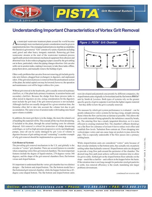
Figure 1: PISTA® <strong>Grit</strong> Chamber<br />
Other costly problems that can arise from not removing grit include gravity<br />
rake arm failures, plugged heat exchangers in digesters, and unpleasant<br />
odors. If the grit removal process is removed from the pretreatment section<br />
<strong>of</strong> the plant, the initial capital cost may be lowered; however, the operation<br />
and maintenance cost will be larger within a few years.<br />
Without grit removal in the headworks, grit is usually removed in primary<br />
clarifiers, or, if the plant lacks primary treatment, in aeration basins and<br />
secondary clarifiers. Because the sludge from these process tanks is<br />
<strong>of</strong>ten stored in digesters on-site, sizing consideration for the digesters<br />
must include the grit load, if the grit removal process is not included.<br />
Although clarifiers are usually designed for a given retention time, the<br />
formulas <strong>of</strong>ten fail to take into account the volume lost due to grit<br />
accumulation. The same is true <strong>of</strong> aeration tanks with loading rates based<br />
upon volume available.<br />
In addition, the more grit there is in the sludge, the more the related cost<br />
<strong>of</strong> handling this material will be. This extends all the way from dewatering,<br />
if included at the plant, through the actual hauling costs for ultimate<br />
disposal. <strong>Grit</strong> removal is critical for protection <strong>of</strong> sludge dewatering<br />
centrifuges, as well as high-pressure progressive cavity and diaphragm<br />
pumps, since all can be easily damaged by grit. Loss <strong>of</strong> volume in<br />
digesters because <strong>of</strong> grit settling out and “cementing” is another example<br />
<strong>of</strong> why grit removal should be implemented as a process step.<br />
<strong>Grit</strong> <strong>Removal</strong> Systems<br />
The prevailing grit removal mechanism in the U.S. and globally is the<br />
circular or “vortex” grit chamber. There are several features to consider<br />
when comparing vortex flow grit removal chambers. The most important<br />
features include the degree <strong>of</strong> liquid rotation, 270 degrees versus 360<br />
degrees, and the shape <strong>of</strong> the grit removal chambers floor, flat bottom<br />
versus and sloped bottom.<br />
It’s important to understand that the vortex grit chamber has two distinct<br />
designs – flat bottom and sloped bottom. The flat bottom model has a<br />
flat-bottomed grit removal chamber, while the hopper bottom has a 45-<br />
degree cone-shaped bottom. The flat bottom and sloped bottom units<br />
were developed and patented concurrently by different companies, the<br />
sloped bottom units originally in Switzerland and the flat bottom PISTA ®<br />
unit by Smith & Loveless. Both types <strong>of</strong> systems rely on the greater<br />
specific gravity <strong>of</strong> grit to separate it out from the lighter organic material<br />
– but they differ in how the grit is actually removed.<br />
The measure by which grit system performance is evaluated – can be<br />
greatly enhanced in vortex systems by having a long, straight entering<br />
flume where the flow can become as laminar as possible. This allows the<br />
grit to settle instead <strong>of</strong> being agitated by the turbulence caused by bends,<br />
etc. The entering flow has a steady tangential direction, so it is more<br />
efficient in creating rotational flow. The chamber’s effluent should go<br />
out a flat floor for a distance <strong>of</strong> at least 6 feet to reduce weir effect and<br />
establish flow levels. Turbulent flows entrain air. Flows dropping into<br />
vertical pipes vortex and can cause large air pockets to pass down the<br />
pipe. This is especially undesirable if the flow passes into a primary<br />
settling basin.<br />
While sloped-bottom units are considered “vortex” units because <strong>of</strong><br />
their circular similarity to flat-bottom units, they actually rely on particle<br />
settling rather than hydraulic removal. Sloped bottom units are designed<br />
to provide a long flow path around the perimeter <strong>of</strong> the chamber. The<br />
desired long flow path must achieve sufficient retention time to allow<br />
for grit to settle. Settled grit on the sloped-bottom floor subsides on the<br />
slope – much like a clarifier – and collects in the hopper below the basin.<br />
If the retention time is not long enough for particular sized grit particles<br />
to settle, less removal efficiency is the result, translating into larger<br />
problems downstream.<br />
continued on reverse side<br />
9503-1 ©2007 Smith & Loveless Inc.<br />
Online: smithandloveless.com • Phone: 913.888.5201 • FAX: 913.888.2173<br />
Smith & Loveless Inc. System Innovators for global pumping, water and wastewater treatment
PISTA ® <strong>Grit</strong> <strong>Removal</strong> System<br />
PISTA ® <strong>Grit</strong> <strong>Removal</strong> System<br />
continued from front side<br />
The flat-bottom PISTA ® <strong>Grit</strong> Chamber (Figure 1, Page 1) works on the<br />
principle <strong>of</strong> a forced vortex. The incoming flow is straightened in the<br />
inlet flume to minimize turbulence at the inlet <strong>of</strong> the chamber. At the end<br />
<strong>of</strong> the inlet flume is a ramp that produces a Coanda effect, which causes<br />
grit that may already be on the flume bottom to follow the ramp to the<br />
floor <strong>of</strong> the chamber and be captured. In addition, at the end <strong>of</strong> the flume<br />
is the inlet baffle. This inlet baffle is positioned such that the flow entering<br />
the chamber and the flow inside the chamber impinge. At the center <strong>of</strong><br />
the chamber are rotating paddles, which maintain the proper circulation<br />
in the chamber at all flow rates. This combination <strong>of</strong> paddles, inlet baffle<br />
and inlet flow produces a toroidal flow pattern, which is key for creating<br />
hydraulic removal ability.<br />
PISTA ® <strong>Grit</strong> Chamber flat bottom grit basins, by the nature <strong>of</strong> their operation,<br />
avoid the problems inherent to hopper bottom grit basins. In the flat bottom<br />
grit chamber, the forced vortex turns the upper area <strong>of</strong> entering flow and<br />
rotates it to the chamber floor where the grit finally passes along the floor.<br />
The grit becomes attached to the floor. This is accomplished by centrifugal<br />
force <strong>of</strong> the rotating tank contents causing the surface <strong>of</strong> the vessel at the<br />
perimeter to be at a higher elevation as shown in the figure. The surface<br />
level at the center is lower. The surface <strong>of</strong> the vessel is a parabola. The<br />
secondary induced flow, shown by the arrows, goes down the outside<br />
wall, across the floor where the grit is deposited, back up the center core<br />
and across the surface. The blades on the center propeller are above the<br />
floor, increasing the flow along the floor and directing it up the center core<br />
from below the impeller to the surface.<br />
Most importantly, the flow path is not around the perimeter, as in the<br />
sloped bottom, settling-type unit. Instead as the basin contents rotate, the<br />
flow moves across the floor to the center <strong>of</strong> the basin. This movement is<br />
accomplished in one full rotation <strong>of</strong> the tank contents. The flow up the<br />
center core to the surface and across the surface is accomplished in the<br />
next rotation. The flow path is not simply the distance <strong>of</strong> the grit basin,<br />
but two revolutions <strong>of</strong> the grit chamber’s paddles. The result is a<br />
substantially longer grit flow path and thus a higher removal efficiency.<br />
The removed grit on the floor <strong>of</strong> the flat bottom basin is moved along the<br />
floor by the hydraulic current to the center. At the center, the propeller<br />
above the floor aids this flow by pumping the hydraulic flow, which<br />
increases flow and velocity. The grit moving on the floor falls into the hole<br />
at the center, and drops into the grit storage chamber to settle quiescently.<br />
The toroidal flow pattern maximizes the number <strong>of</strong> times a grit particle can<br />
be subjected to hitting the chamber floor and be captured. Once captured<br />
on the flat floor <strong>of</strong> the chamber, the grit is moved along the floor toward the<br />
center by the bottom velocity created by the toroidal flow pattern. A flat<br />
chamber bottom is essential to maintaining the toroidal flow pattern at its<br />
maximum efficiency. A sloping bottom would decrease the intensity <strong>of</strong> the<br />
toroidal flow pattern, reducing the grit capture efficient and increasing the<br />
amount <strong>of</strong> organics that will be captured and contained in the grit.<br />
As the solids are moved along the flat floor <strong>of</strong> the chamber toward the<br />
center, the rotating paddles maintain a velocity such that the lighter organic<br />
materials are lifted and returned to the flow passing through the grit<br />
chamber. The grit then moves toward the center and drops into the bottom<br />
storage chamber through a small opening between the paddle drive shaft<br />
and the steel cover plate. All grit passes under the paddles to remove<br />
organic materials before being allowed to fall into the storage chamber.<br />
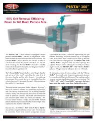
In terms <strong>of</strong> removal efficiency, the flat-bottom grit chamber is capable <strong>of</strong><br />
removing the following at the specified hydraulic peak flow rate: 95% <strong>of</strong><br />
the grit greater than 50 mesh in size, 85% <strong>of</strong> the grit greater than 70 but<br />
less than 50 mesh in size, 65% <strong>of</strong> the grit greater than 100 but less than<br />
70 mesh in size.<br />
When sufficient grit has accumulated in the storage chamber, the grit is<br />
then removed from the chamber and transferred to dewatering devices.<br />
In vortex grit chambers, removed grit collects in the storage hopper<br />
below the chamber floor. Superior grit chamber units will <strong>of</strong>fer a<br />
fluidizing option in the storage hopper to prevent grit from compacting<br />
and cementing.<br />
Once removed from the main wastewater flow stream, grit is conveyed<br />
out <strong>of</strong> the storage hopper by various means, most notably airlifts and<br />
turbo grit pumps. Airlifts can be useful – typically on small flow<br />
applications – but will plug more <strong>of</strong>ten and prevent the use <strong>of</strong> a vortex<br />
separator component (i.e. grit concentrator or cyclone) in the grit<br />
dewatering phase. Airlifts represent conventional technology that has<br />
been replaced with heavy-duty grit pumps, particularly in large flow<br />
applications (12 MGD and larger).<br />
<strong>Grit</strong> pumps employed in these applications are centrifugal, and the superior<br />
ones feature a Ni-hard construction. They can be remote-mounted, using<br />
gravity flow or be top-mounted on the grit chamber using vacuumpriming.<br />
Top mounted designs <strong>of</strong>fer unique advantages including a selfdraining<br />
capability, which minimizes the potential for clogging. The suction<br />
pipe is a vertical rise where the grit can flow back into the storage hopper.<br />
Remote mounted units require additional suction piping where material<br />
can accumulate and increase the potential for clogging. In addition, topmounted<br />
grit pumps minimize space and construction cost because they<br />
don’t require additional dry wells; instead they simply reside on top <strong>of</strong><br />
the grit chamber.<br />
Conclusion<br />
<strong>Grit</strong> removal has become an important stage in the wastewater treatment<br />
process for protecting down stream equipment and operating efficiency.<br />
As the removal technology advances with time, it has become important<br />
to understand the dynamics <strong>of</strong> grit chamber operation to properly<br />
implement an effective removal system. The latest market trend shows<br />
that grit chamber installations are using more and more vortex grit chamber<br />
features, including flat bottom chambers, top mounted grit pumps (nonairlifts),<br />
and 360 degree rotations.<br />
Online: smithandloveless.com • Phone: 913.888.5201 • FAX: 913.888.2173<br />
Smith & Loveless Inc. System Innovators for global pumping, water and wastewater treatment