Datasheet - Flow meter
Datasheet - Flow meter
Datasheet - Flow meter

You also want an ePaper? Increase the reach of your titles
YUMPU automatically turns print PDFs into web optimized ePapers that Google loves.
n<br />
a<br />
h<br />
S<br />
U<br />
IV<br />
co<br />
d<br />
E<br />
R<br />
g<br />
Fl<br />
l<br />
e<br />
n<br />
ow<br />
M<br />
o<br />
n<br />
it<br />
oring s<br />
i<br />
c<br />
e<br />
rt<br />
ifie<br />
d<br />
a<br />
c<br />
r<br />
in<br />
C<br />
n<br />
t<br />
pe<br />
o<br />
O<br />
MC<br />
N<br />
Sira MC110189/00<br />
T<br />
S<br />
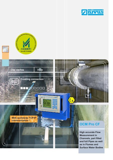
Dial device<br />
Help<br />
Creating connection<br />
With worldwide TCP/IP<br />
communication !<br />
OCM Pro CF<br />
High accurate <strong>Flow</strong><br />
Measurement in<br />
Channels, part filled<br />
and full Pipes as well<br />
as in Flumes and<br />
Surface Water Bodies
OCM Pro CF<br />
New in the <strong>Flow</strong> Measurement Area<br />
NIVUS flow measurement technology stands for innovation and high<br />
accuracy.<br />
The new OCM Pro CF is a permanent measurement system for<br />
continuous flow measurement, flow control and storage of recorded<br />
data in a range from slight to heavily polluted media of various<br />
consistencies.<br />
It is designed for use in part filled and full pipes, channels and flumes<br />
with many different shapes and dimensions.<br />
The OCM Pro CF is equipped with fast processors and offers online<br />
access via the Internet. This ensures more versatile, more reliable and<br />
more economic operation.<br />
2
Overview on Transmitter Details<br />
<br />
<br />
<br />
<br />
<br />
<br />
<br />
<br />
very high accuracy<br />
measures the real flow velocity<br />
profile<br />
spatial allocation of single velocities<br />
cross correlation with digital pattern<br />
detection<br />
absolutely stable zero point and<br />
drift-free<br />
no electrodes, no conductivity<br />
required<br />
measures in all channels,<br />
part filled and full pipes and flumes<br />
measures in heavily polluted<br />
and abrasive media<br />
<br />
<br />
<br />
<br />
<br />
<br />
<br />
<br />
<br />
no external calibration required<br />
suitable even for very difficult<br />
applications<br />
easy installation without additional<br />
constructions<br />
Ex approval for zone 1 as ATEX<br />
very easy para<strong>meter</strong> setting in<br />
multilingual dialog mode<br />
large, back-lit graphic display<br />
stores complete measurement data<br />
on Compact Flash card<br />
worldwide TCP/IP communication<br />
online connection/data transmission<br />
and remote maintenance via Internet<br />
Lift-up mechanism for inspection purposes or for sensor removal under operational conditions<br />
3
OCM Pro CF<br />
Sensors - high accuracy and universal use<br />
A complete OCM Pro CF measurement place consists of a transmitter and appropriate<br />
active sensors. There are flow velocity sensors with and without integrated<br />
flow level measurement available as well as air-ultrasonic flow level sensors for<br />
direct connection to OCM Pro CF. Various constructions can be used depending<br />
on the kind of application. You can select from wedge sensors for installation in<br />
channels and open flumes or pipe sensors for installation in steel, concrete and<br />
plastic pipes.<br />
Air-ultrasonic sensor<br />
+<br />
no modifications or additional constructions<br />
at place of installation<br />
triple redundant level measurement<br />
(air-ultrasound, water-ultrasound,<br />
hydrostatic)<br />
measurement dynamics between<br />
5 mm/s and 6 m/s<br />
measures in both flow directions<br />
highly medium-resistant standard<br />
+<br />
+<br />
+<br />
+<br />
sensors (PPO, PEEK, 1.4571,<br />
Hastelloy C276)<br />
+<br />
sensors resistant to chemicals for<br />
highest demands<br />
cables can be extended without any<br />
problems<br />
Ex approval zone 1 as ATEX<br />
protection rating IP 68<br />
+<br />
+<br />
+<br />
Water-ultrasonic sensor<br />
Pipe sensor<br />
The wedge sensor operates absolutely<br />
reliably despite heavy soiling.<br />
Simple pipe sensor mounting.<br />
4
Successful in use anywhere<br />
<strong>Flow</strong> measurement in rectangular<br />
channel of a sewage treatment plant<br />
Due to heavy vorticity 3 sensors have been<br />
installed. Since initial start-up in December<br />
2001 the measurement runs without<br />
interruption.<br />
Standard sensor installed<br />
on a wedge<br />
Due to heavy sedimentation in the<br />
channel it was necessary to install<br />
this special construction. The<br />
measurement operates reliably since<br />
initial installation.<br />
Guiding tube DN 100<br />
Length 8m<br />
Measurement in a full filled<br />
recirculation line<br />
A full filled recirculation pipe is on the<br />
ground of a constantly filled denitrification<br />
tank. The measurement in the filled tank<br />
was desired to be accessible at any time.<br />
The flow velocity sensor has been installed<br />
in a guiding tube with a length of 8 m.<br />
Recirculation pipe<br />
DN800<br />
Typical areas of use<br />
for OCM Pro CF<br />
+<br />
wastewater treatment plants: inlet,<br />
discharge, inlet to aeration tanks,<br />
return sludge, recirculation, surplus<br />
sludge, discharge from digester and<br />
flocculant dosing point<br />
permanent measurements on storm<br />
water basin, storm water retention<br />
basin, storm water sedimentation tank<br />
direct discharger control, investigation<br />
of extraneous water or leakage<br />
industrial wastewater networks<br />
+<br />
+<br />
+<br />
+<br />
+<br />
+<br />
industrial flow measurements<br />
irrigation systems<br />
inlets and outlets conducting cooling<br />
water or circulation systems<br />
sluice stages in rivers<br />
hydroelectric and thermic power<br />
plants<br />
measurement campaigns in channel<br />
networks<br />
MCERTS applications<br />
and many more<br />
+<br />
+<br />
+<br />
+<br />
+<br />
5
OCM Pro CF<br />
NIVUS - the perfect Solution for each Application<br />
Due to decades of experience and<br />
knowledge of our engineers and<br />
technicians almost impossible<br />
applications are our challenge. If<br />
desired, you can let us do the<br />
complete planning and evaluation<br />
of your measurement place.<br />
v<br />
h<br />
Exemplified measurement tasks:<br />
A flow measurement which is insensitive<br />
to soiling and sedimentation without the<br />
need to be cleaned frequently. The<br />
measurements shown in the examples<br />
have been developed in order to reliably<br />
and accurately detect flow levels<br />
considering fluctuations of sludge layers.<br />
In this case OCM measurements with<br />
combi wedge sensors have been used<br />
which e.g. were placed on the water<br />
surface by using vertically movable<br />
“floats”.<br />
The prevailing water level down to the<br />
sludge surface is going to be detected<br />
by using the ultrasonic transit time<br />
method.<br />
The flow velocity sensor thanks to the<br />
cross correlation provides the accurate<br />
flow velocity profile and hence an<br />
accurate image of the flow conditions<br />
and the flow velocity in the channel.<br />
You need an individual solution for your<br />
measurement problem or you are<br />
interested in more application examples<br />
and references?<br />
Just talk to us.<br />
6
How the OCM Pro CF measures<br />
The quantity >>flow "Q"
OCM Pro CF<br />
Q flow<br />
v average<br />
v max<br />
V<br />
<strong>Flow</strong> Velocity Measurement<br />
GPRS<br />
The OCM Pro CF in conjunction with the new combi sensors has the<br />
ability to carry out high accurate flow measurements.<br />
Solar<br />
The principle of flow velocity determination is based on the ultrasonic<br />
reflection principle. One of the latest and most efficient methods for flow<br />
velocity detection is the correlation method (interrelation between two<br />
similar image patterns). A prerequisite for being applied is the existence<br />
of reflecting particles (solids, minerals or gas bubbles) in the fluid.<br />
This allows to exactly allocate the measured velocities spatially and to<br />
indicate the results.<br />
8
... thanks to Cross Correlation<br />
An ultrasonic converter (sensor) sends<br />
an ultrasonic burst into the medium.<br />
The particles or gas bubbles in the medium<br />
reflect this impulse.<br />
The sensor operates in impulse-echo<br />
mode, i.e. the ultrasonic converter will<br />
switch to receiving mode immediately<br />
after transmitting the burst, receiving<br />
the reflected ultrasonic echo as a characteristic<br />
echo image pattern.<br />
A spatial allocation can be derived thanks<br />
to the transit time of the ultrasonic impulse<br />
and the sound velocity.<br />
These echo patterns from the first scan<br />
will be digitised and saved.<br />
E4<br />
E Measurement windows 4 - 16<br />
n<br />
E2<br />
E1 - E4 =<br />
Reflecting particels<br />
1. Scan<br />
E3<br />
Measurement window 3<br />
E1<br />
Measurement window 2<br />
Measurement window 1<br />
During the second scan, an ultrasonic<br />
burst will be sent again and the reflected<br />
echo pattern will be saved as well.<br />
By using the cross correlation method<br />
the characteristic echo image patterns<br />
within the time slots are now checked<br />
for compliance.<br />
12<br />
10<br />
8<br />
6<br />
4<br />
2<br />
0<br />
E4<br />
E2<br />
E1 - E4 =<br />
Reflecting particels<br />
2. Scan<br />
Overlay of image patterns<br />
0 5 10 15 20 25 30 35 40 45<br />
1. Scan<br />
2. Scan<br />
∆t<br />
Signal<br />
evaluation<br />
E Measurement windows 4 - 16<br />
n<br />
E3<br />
0<br />
Window 1<br />
E1<br />
E1<br />
t1<br />
Measurement window 3<br />
E1<br />
Measurement window 2<br />
Window 2<br />
E2<br />
t2<br />
Measurement window 1<br />
The temporal shift between the echo<br />
image patterns from both scans is going<br />
to be investigated.<br />
This comparison allows to directly convert<br />
the flow velocities prevailing within<br />
the single measurement windows considering<br />
the beam angle.<br />
E2<br />
Window 3<br />
E3<br />
t3<br />
E3<br />
t<br />
t<br />
t<br />
E4<br />
∆t<br />
+ T / 2<br />
V<br />
x y ϕ<br />
(t) (t-t)<br />
( ) lim 1<br />
fg<br />
τ = f(t) g(t ) dt<br />
t→∝<br />
T ∫ ⋅ + τ<br />
0.0 0.2 0.4 0.6 0.8 1.0<br />
Formula<br />
98<br />
96<br />
94<br />
92<br />
90<br />
0.0 0.2 0.4 0.6 0.8 1.0<br />
86<br />
80<br />
70<br />
−T / 2<br />
This procedure will be repeated up to<br />
2000 times per second. The flow profile<br />
will be determined from the individual velocities<br />
in real time by the integrated digital<br />
signal processor (DSP).<br />
This allows the user to obtain measurement<br />
values with the highest accuracy<br />
without additional calibration.<br />
v 1<br />
v 3<br />
v 2<br />
Investigated flow profile<br />
<strong>Flow</strong> profile directly indicated<br />
on the display.<br />
Values can be read directly<br />
on the display.<br />
9
OCM Pro CF<br />
Always up-to-date<br />
Operation / Programming<br />
Data Storage<br />
Evaluation<br />
It is very easy to put the system into<br />
operation and to recall data since the<br />
large graphic display is clearly laid out<br />
for its various applications.<br />
Settings are clearly indicated on the<br />
graphic display. This virtually eliminates<br />
faulty programming.<br />
Any of the recorded readings as well<br />
as up to 4 additional external analog<br />
signals can be saved in free intervals<br />
if the OCM Pro CF has been equipped<br />
with a Compact Flash card.<br />
Data can be read and evaluated easily.<br />
Diagnostics<br />
The status of analog and digital inputs<br />
can be indicated and recalled directly.<br />
System failures or irregularities which<br />
might have occurred will be recorded as<br />
well.<br />
Versatile diagnostic options enable the<br />
choice of the best possible measurement<br />
place and error free operation of<br />
the measurement system.<br />
The OCM Pro CF comes with the free<br />
evaluation software NivuDat which, besides<br />
using other common spreadsheet<br />
applications, allows the indication of<br />
measurement data such as graphs or<br />
tables under Windows XP / Windows<br />
2000 quick and clearly.<br />
This ensures the read-out of saved raw<br />
data very reliable. Additional processing<br />
functions such as sequential data export,<br />
averaging, output of min. and max. values,<br />
measurement place management<br />
and more complete the program.<br />
The clear program structure allows<br />
to easily set para<strong>meter</strong>s.<br />
Recall the most important system data<br />
on-site or comfortably on PC.<br />
10
On-site from anywhere<br />
<br />
<br />
<br />
<br />
<br />
<br />
<br />
complies with worldwide interface<br />
standard using TCP/IP Ethernet<br />
integrated web server<br />
online access via Internet browser<br />
without the need to install<br />
additional software<br />
integrated data logger up to 128 MB<br />
saved data can be read out<br />
via Internet at any time<br />
operation and para<strong>meter</strong> setting<br />
online (remote control)<br />
quick and comprehensive remote<br />
diagnosis of entire measurement<br />
place (online service)<br />
Integrated<br />
Web Server<br />
The OCM Pro CF offers innovative communication options for<br />
remote maintenance, remote diagnosis and data transfer as<br />
standard. This is how to interconnect the latest measurement<br />
technology worldwide at any time.<br />
Using its integrated web server the<br />
OCM Pro CF provides a dedicated website<br />
using TCP/IP. Besides being used<br />
within internal networks this option allows<br />
the user to connect the unit to the<br />
world wide web. Due to the specially designed<br />
operating system the unit is absolutely<br />
resistant to virus attacks.<br />
Remote control options enable to access<br />
any functions which are available<br />
on site.<br />
The screen indicated is equal to the onsite<br />
display.<br />
Data can be transferred simply by one<br />
mouse click. Internet connection enables<br />
the user to maintain, control and analyse<br />
several measurement places from<br />
anywhere in the world simultaneously.<br />
Visit www.nivus.com<br />
and check out communication with<br />
our new OCM Pro CF<br />
www.nivus.com<br />
Log in using your password<br />
on www.nivus.com<br />
Connection to measurement<br />
place will be set up<br />
Select display<br />
mode<br />
11
S p ec ifica t ions ar e sub jec t to cha n ge. 1 5 .0 4. 2 01 0<br />
Specifications<br />
258.5<br />
13.35<br />
Water-Ultrasonic<br />
Combi Sensor<br />
Air-Ultrasonic<br />
Level Sensor<br />
Pipe Sensor<br />
OCM Pro CF<br />
Memory Card<br />
243.5<br />
5.5<br />
Transmitter<br />
120<br />
90<br />
236.7<br />
28<br />
4<br />
11<br />
236<br />
(207.5 without transparent cover)<br />
70<br />
Transparent cover<br />
22.5<br />
Slotted holes for fastening on pipe mounting system<br />
17.5<br />
24<br />
40<br />
Countersunk holes DIN 66-5, but with<br />
d1 = ø6.5 mm, for direct fastening<br />
ø6.5<br />
ø10.4<br />
320<br />
237<br />
12 17<br />
45°<br />
90°<br />
3<br />
M16<br />
24<br />
40<br />
7.5<br />
Countersunk holes DIN 66-5, but with<br />
d1 = ø6.5 mm, for direct fastening<br />
17.5<br />
320<br />
254.5<br />
Three adapter plates are required for fastening on<br />
pipe mounting system.<br />
31<br />
45°<br />
M16<br />
3<br />
Type R2: 200 /<br />
Type R3: 300 (with stop ball valve) 15.5<br />
22<br />
SW55<br />
SW50<br />
ø35<br />
G1½”<br />
74.8<br />
alignment screw<br />
M4 x 80<br />
(”installation help”)<br />
M16x1,5<br />
movable<br />
22<br />
68.5<br />
retaining<br />
element<br />
All dimensions in mm<br />
All dimensions in mm<br />
Transmitter<br />
Supply power<br />
100 to 240 V AC, +10 % /-15 %, 47 to 63 Hz<br />
or 24 V DC ± 15 %, 5 % residual ripple<br />
Power consumption max. 20 VA<br />
Material/Weight Polycarbonate, approx. 3400 g<br />
Protection IP 65<br />
Ex Approval<br />
II(2)G [Ex ib] II B<br />
Operating temperature -20 °C to +50 °C<br />
Storing temperature -30 °C to +70 °C<br />
Max. Humidity<br />
80 %, non-condensing<br />
Display<br />
back-lit graphic display,<br />
128 x 128 Pixel<br />
Operation<br />
18 button keypad, menus in German, English,<br />
French, Italian, Spanish, Polish, Danish, ...<br />
Inputs<br />
1 x 4 - 20 mA for external level<br />
1 x RxTx-Bus for NIVUS air-ultrasonic sensor<br />
Type LUS<br />
up to 4 x 0/4 - 20 mA with 12 bit resolution for<br />
external level, external setpoints and<br />
data storage<br />
up to 4 digital inputs<br />
up to 3 velocity sensors<br />
Outputs<br />
up to 4 x 0/4 - 20 mA, load 500 Ohm,<br />
12 bit resolution,<br />
up to 5 relays/SPDT<br />
Data memory<br />
Compact Flash Card up to 128 MB<br />
Storage cycle<br />
1 to 60 minutes<br />
Data transmission Compact Flash Card, TCP/IP via Ethernet<br />
and modem (GPRS, ISDN, analog)<br />
Connection<br />
Modbus TCP and TCP/IP via Ethernet<br />
and modem (GPRS, ISDN, analog)<br />
You can find more information in the instruction manual or on www.nivus.com<br />
Sensors<br />
Measurement principle ultrasonic transit time (level/height)<br />
piezoresistive pressure meas. (level/height)<br />
correlation with digital pattern detection<br />
(flow velocity)<br />
Measurement range (v) -1 m/s to +6 m/s<br />
Measurement range (h) pressure 3.5 m; ultrasonic 2 m<br />
Measurement frequency 1 MHz<br />
Protection IP 68<br />
Ex Approval<br />
II 2 G Ex ib IIB T4<br />
Operating temperature -20 °C to +50 °C (-20 °C to +40 °C in Ex Zone 1)<br />
Storing temperature -30 °C bis +70 °C<br />
Measurement deviation less than 1 %,<br />
uncertainty<br />
(in case of compliance with specific conditions)<br />
Operational pressure max. 4 bar (combi sensor with pressure<br />
measurement cell max. 1 bar)<br />
Cable length<br />
max. 100 m, other lengths on request<br />
Sensor types<br />
V100 flow velocity sensor (v; temperature)<br />
V1H1 combi sensor (v meas., level meas.using<br />
water-ultrasound and temperature meas.)<br />
V1D0 combi sensor (v meas., level meas. using<br />
pressure and temperature meas.)<br />
V1U1 combi sensor (v meas., level meas. using<br />
water-ultrasound and redundancy using pressure<br />
and temperature measurement)<br />
Constructions<br />
wedge sensor for installation on channel bottom<br />
pipe sensor incl. retaining element for<br />
installation in pipes<br />
Materials<br />
Polyurethane, stainless steel 1.4571, PPO GF30,<br />
PA (only wedge sensor),<br />
HDPE (only pipe sensor)<br />
Option<br />
PEEK, Hastelloy C276 ground plate;<br />
Titanium ground plate; FEP-coated cable<br />
NIVUS GmbH NIVUS AG NIVUS Sp. z o.o. NIVUS France<br />
NIVUS U.K.<br />
Im Taele 2 Hauptstrasse 49<br />
ul. Hutnicza 3 / B-18 14, rue de la Paix P.O. Box 342, Egerton, Bolton<br />
75031 Eppingen, Germany 8750 Glarus, Switzerland 81-212 Gdynia, Poland 67770 Sessenheim, France Lancs. BL7 9WD, U.K.<br />
Phone: +49 (0) 72 62 / 91 91 - 0 Phone: +41 (0) 55 / 645 20 66 Phone: +48 (0) 58 / 760 20 15 Phone: +33 (0) 3 88 07 16 96 Phone: +44 (0) 1204 591559<br />
Fax: +49 (0) 72 62 / 91 91 - 999 Fax: +41 (0) 55 / 645 20 14 Fax: +48 (0) 58 / 760 20 14 Fax: +33 (0) 3 88 07 16 97 Fax: +44 (0) 1204 592686<br />
E-mail: info@nivus.com E-mail: swiss@nivus.com E-mail: poland@nivus.com E-mail: france@nivus.com E-mail: info@nivus.com<br />
Internet: www.nivus.de Internet: www.nivus.de Internet: www.nivus.pl Internet: www.nivus.com Internet: www.nivus.com