DUPLEX Tx - rc-easy.com
DUPLEX Tx - rc-easy.com
DUPLEX Tx - rc-easy.com

You also want an ePaper? Increase the reach of your titles
YUMPU automatically turns print PDFs into web optimized ePapers that Google loves.
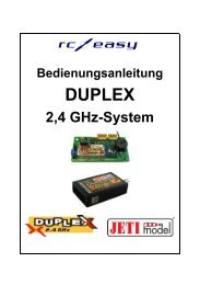
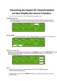
<strong>DUPLEX</strong> <strong>Tx</strong><br />
<strong>DUPLEX</strong> <strong>Tx</strong> transmitter modules (along with <strong>DUPLEX</strong> Rx receceivers) constitute the<br />
base of a <strong>com</strong>plex system working in the 2,4GHz band, assigned to remote control of models.<br />
These modules may be installed into transmitters which in a convenient way transmit stick<br />
and control element positions. Recently most of available transmitters working with PPM<br />
mode are suitable for this purpose.<br />
<strong>DUPLEX</strong> <strong>Tx</strong> modules work up data of the transmitter control elements and send them<br />
to the corresponding (paired) receiver. Simultaneously they exchange service and telemetric<br />
informations with the receiver and take in turn advantage of them for operation optimization.<br />
In order to take full advantage of the <strong>DUPLEX</strong> system it is advisable to connect the universal<br />
terminal JETIBOX to the transmitter module. This way you will be able to adjust easily<br />
requested parameters and to display data of transmitter, receiver as well as data of connected<br />
telemetric or diagnostic equipment. Another item of the TX-modules is indication of the<br />
<strong>com</strong>plete system condition by means of sound signals.<br />
Transmitter modules of the <strong>DUPLEX</strong> system are offered in form of exchangeable<br />
plug-in modules <strong>DUPLEX</strong> TF, <strong>DUPLEX</strong> TG as well as modules <strong>DUPLEX</strong> TU for internal<br />
assembly.<br />
Table 1 Basic Data of TX Modules:<br />
Basic data <strong>DUPLEX</strong> TU <strong>DUPLEX</strong> TF <strong>DUPLEX</strong> TG<br />
Dimensions 55 x 28,8 x 9 mm 59 x 37 x 20 mm 60 x 44 x 21 mm<br />
Weight 15 g 40 g 50 g<br />
Antenna 2 dBi 2 dBi 2 dBi<br />
Acoustic signalling of conditions • • •<br />
Number of input PPM channels 16 16 16<br />
Operation temperature - 10 to + 85° C - 10 to + 85° C - 10 to + 85° C<br />
Supply voltage 3,5 – 16V 3,5 – 16V 3,5 – 16V<br />
Average current 38 mA 38 mA 38 mA<br />
Output power 20 dBm 20 dBm 20 dBm<br />
Table 2 Assignment of Modules and Transmitters<br />
Transmitter <strong>DUPLEX</strong> TU <strong>DUPLEX</strong> TF <strong>DUPLEX</strong> TG<br />
Futaba: 7U, 8U, 8J, 9C,9Z, FC-18, FN, 3PK, 3PJ • • -<br />
Hitec: Optic 6, Eclipse 7 • • -<br />
Graupner/JR: X-347, X-388, X-3810 ADT,<br />
X-9303, PCM-10S, PCM-10X, MX22 • - •<br />
FM-6014, MC-17, MC-18, MC-20, MC-24<br />
MC-19, MC-22 • - -<br />
Multiplex: Série 7,9,12, Profi 3000, 4000 • - -<br />
Other transmitters • - -<br />
Installation of <strong>DUPLEX</strong> TF and <strong>DUPLEX</strong> TG Modules<br />
<strong>DUPLEX</strong> TF and TG modules are assigned to transmitters with exchangeable HF<br />
plug-in modules. TF modules are <strong>com</strong>patible to corresponding exchangeable modules of<br />
Futaba and Hitec transmitters. TG modules are assigned to Graupner and JR transmitters.<br />
Factual assignments see Table 2.<br />
- 1 -
<strong>DUPLEX</strong> <strong>Tx</strong><br />
Remove the original HF module of your transmitter and plug-in with the correct<br />
orientation of the connector the <strong>DUPLEX</strong> TF or TG in place of the original module. Screw<br />
the <strong>Tx</strong>-antenna delivered with the <strong>Tx</strong> module into the module box.<br />
Installation of the <strong>DUPLEX</strong> TU Module<br />
Place of destination of the <strong>DUPLEX</strong> TU transmitter modules are transmitters working<br />
in PPM mode, but without having exchangeable HF module.<br />
In this case connection of the module to the transmitter affords certain skill and experience<br />
with electronic equipment. The skill necessary depends upon the type of transmitter and upon<br />
the manner you intend to connect it up. On PPM transmitters with a „trainer“ connector the<br />
transmitter module can be connected to this connector. Other transmitters require removal of<br />
the <strong>Tx</strong> back cover in order to assemble the module <strong>DUPLEX</strong> TU directly inside the<br />
transmitter. For this kind of work we re<strong>com</strong>mend to take advantage of the help of a service<br />
station. An acute list of appropriate centers you may find on the home page of<br />
www.jetimodel.cz.<br />
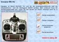
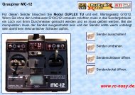
Installation with the Aid of the Trainer Connector<br />
Find the connections of the trainer connector in the instruction manual of your<br />
transmitter, connections of several transmitters are shown below. In order to insure correct<br />
operation of the <strong>DUPLEX</strong> TU module jou have to inte<strong>rc</strong>onnect the corresponding pins GND,<br />
supply +Ubat and the PPM signal between the transmitter and the IN connector of the<br />
module. Mechanically you may fix the module and the connector either to the transmitter case<br />
or the transmitter tray.<br />
Internal Installation<br />
Switch off the transmitter and place it on a soft pad in order to prevent mechanical<br />
damage. Remove the cover and before proceeding remove batteries. Select an appropriate<br />
location in your transmitter for assembly, keeping placement of the antenna connector in<br />
mind. Mechanical fixing of the module you may a<strong>com</strong>plish by means of double sided tape,<br />
Velcro fastener or by small screws through holes provided in the module.<br />
For installation of the antenna connector you may usually take advantage of one of the holes<br />
provided for additional switches, the hole for the existing antenna 35/40 MHz, or you may<br />
drill a 6,5 mm dia. hole at an appropriate location. In any case, the part of the connector<br />
protruding through the transmitter wall should be long enough (after screwing the antenna in<br />
there must remain at least a small gap between transmitter case and antenna.<br />
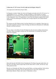
The <strong>DUPLEX</strong> TU module is equipped with two 4-pin connectors marked IN and OUT. The<br />
IN connector is specified for the connection of the battery supply and of the PPM signal from<br />
the encoder of your transmitter. To the connector OUT you may connect another transmitter<br />
module (for instance a redundant module). The supply of this module is provided by the cross<br />
connection „FM“ (Fail Safe Module), if the cross connection „FM“ is removed there is no<br />
supply at the connector OUT. In a similar manner the supply of the <strong>DUPLEX</strong> TU can be<br />
- 2 -
<strong>DUPLEX</strong> <strong>Tx</strong><br />
handled by the cross connection „2,4“ (when the cross connection „2,4“ is removed supply of<br />
the <strong>DUPLEX</strong> TU module is cut).<br />
Examples of accessible installations of well-known transmitters you may find on internet<br />
pages of www.jetimodel.cz.<br />
Putting into operation<br />
Pairing with the receiver and performance verification<br />
Any receiver and transmitter module takes advantage of digital transfer for<br />
<strong>com</strong>munication purposes, in order to enable direct address <strong>com</strong>munication between the<br />
equipment it is necessary to apply the so called pairing between them. The description of a<br />
transmitter module is given by its unique address which after pairing to the receiver ensures,<br />
that the receiver will accept only data from this definite transmitter. There may be paired as<br />
many receivers as you like with the transmitter module, but a receiver can be paired to one<br />
transmitter only.<br />
Install the receiver into your model. If the equipment is switched on first time we<br />
explicitly re<strong>com</strong>mend to ensure that no detrimental effects on health or property may occur<br />
due to unexpected receiver output conditions (for instance badly adjusted mixers, reversed<br />
outputs etc.).<br />
Activate receiver pairing by means of the shorting plug (BIND PLUG), which is a<br />
part of the receiver. Plug-in the shorting plug into the connector "Ext." and switch on the<br />
receiver. Then switch on the transmitter. If pairing was successful the transmitter will<br />
confirm this by a short beep (by a lower and then a higher tone). If no confirmation of a<br />
successful pairing occurs, try to repeat the whole procedure or try to verify via the JETIBOX<br />
whether the receiver is in „Normal Mode“ (a receiver in „Clone Mode“ is not allowed to<br />
transmit and hence cannot confirm pairing). After pairing confirmation remove the BIND<br />
PLUG from the receiver connector.<br />
Verify correct reactions of the model to transmitter <strong>com</strong>mands (servo deflections have to<br />
follow corresponding stick deflections). If not, check whether servos are plugged into correct<br />
positions and the receiver is correctly adjusted (adjustment of mixers etc.). <strong>DUPLEX</strong><br />
receivers can be reset to original state by the JETIBOX (connected to the receiver) with the<br />
help of the menu Autoset-normal.<br />
<strong>DUPLEX</strong> <strong>Tx</strong> modules are adapted to cooperate with transmitters working with PPM signals.<br />
If the transmitter is switched to PCM mode or the installation has not been performed<br />
properly, the transmitter module will emit a repeated allert tone (3x long beep).<br />
- 3 -
<strong>DUPLEX</strong> <strong>Tx</strong><br />
Range test<br />
Before initial utilization of the transmitter (or receiver) it is advisable to make a range<br />
test and thus verify correct functions of the transmitter and receiver HF ci<strong>rc</strong>uits. The<br />
transmitter can be switched to the test mode by the JETIBOX or by the BIND PLUG.<br />
After connection of the JETIBOX to the transmitter select the item "Range Test" and<br />
push the button U (upward arrow). The transmitter will be switched to range test mode and<br />
the transmitted power will be decreased to less than 10%. This situation is reported<br />
acoustically by interrupted beeps (short and long tone). After 60 seconds the transmitter<br />
returns to normal state, the output power increases to the normal value and beeping ceases.<br />
Test mode activation by means of the BIND PLUG <strong>com</strong>mences analogical to receiver pairing<br />
as shown above. However, after the pairing procedure do not unplug the shorting plug of the<br />
receiver. For approximately 60 seconds the transmitter will stay in range test mode. If you<br />
would like to extend this time, just switch the transmitter off and on again. The transmitter<br />
behaves in this mode in the same way as if range test would have been activated by the<br />
JETIBOX.<br />
Place the model and transmitter at least 80 cm high over ground. A correctly working<br />
transmitter and receiver in test mode should have a range of at least 50 m. If not, first of all<br />
verify correct antenna installation (transmitter and receiver). If the test still shows no success,<br />
do not use the equipment and contact your dealer or a service center.<br />
Connection of the JETIBOX<br />
As already mentioned the JETIBOX terminal can be connected to <strong>DUPLEX</strong> <strong>Tx</strong><br />
transmitters. With the help of this terminal transmitter data and parameters as well as<br />
currently connected equipment (receivers, telemetric senzors etc.) may be displayed and<br />
adjusted.<br />
<strong>DUPLEX</strong> transmitter modules are equipped with a three pin connector (see marking)<br />
intended for connection of the JETIBOX. Connection can be easily done by the<br />
inte<strong>rc</strong>onnection cable delivered with the JETIBOX. When connecting pay attention to correct<br />
orientation of the connectors. We re<strong>com</strong>mend to connect or disconnect the JETIBOX only, if<br />
the transmitter is switched off. When the transmitter has been switched on you will be able to<br />
skim through items of the transmitter or other connected equipment with the help of the<br />
JETIBOX push buttons.<br />
Parameter Adjustment with Help of the JETIBOX<br />
When connecting the JETIBOX terminal to the transmitter you may select whether<br />
you want to display and adjust transmitter parameters (<strong>Tx</strong>), connected receivers (Rx) or other<br />
equipment (Mx) which is able to <strong>com</strong>municate with the JETIBOX. Communication with Rx<br />
and Mx is only possible if the transmitter module and receiver are paired and if there exists a<br />
radio link. This situation is shown in the LCD display by a downward showing arrow beside<br />
the Mx and Rx text.<br />
After adjustment of the claimed item (<strong>Tx</strong>/Rx/Mx) push the button D (downward arrow).<br />
Afterwards you may skim with help of pushbuttons through the menu of the selected<br />
equipment. When working with equipment Rx or Mx you may get back to the transmitter<br />
module menu <strong>Tx</strong> by holding down button U (arrow upward) for a time longer than 2 seconds.<br />
The menu structure of the transmitter module as shown by the JETIBOX see Diagram.<br />
- 4 -
<strong>DUPLEX</strong> <strong>Tx</strong><br />
Summary of Transmitter Items:<br />
The introductory display shows the transmitter type. By pushing button R (right arrow) the<br />
identification numbers of the transmitter module and of the actual paired receiver are<br />
displayed.<br />
Diag – shows more detailed informations about the transmitter and paired receiver condition.<br />
Identification of the active receiver antenna (A1/A2).<br />
On the right side according to condition the following indicators may be shown:<br />
R - Range Test mode (range test)<br />
P - after switching on the transmitter has not yet been paired (did for the moment not<br />
yet find a paired receiver)<br />
S - there are no receiver data available (bad signal)<br />
T - low voltage of the transmitter battery<br />
B - low voltage of the receiver battery<br />
I - there are no PPM pulses from the transmitter accessible (installation error, PCM<br />
mode etc.)<br />
Most of the conditions shown are ac<strong>com</strong>panied by acoustic signals.<br />
By pushing button U (upward arrow) range test mode may be activated.<br />
ImpDiag – shows the actual number of transmitter PPM channels (K2 till K16, depends on<br />
transmitter type)<br />
Volt MIN/ACT/MAX - minimum, actual and maximum value of transmitter module supply<br />
voltage. Reset („zeroing“) of the min. and max. values is always executed when the<br />
transmitter is switched on and after location of the paired receiver. Alternatively the displayed<br />
values may be reset by simultaneously pushing buttons L and R (left and right arrow).<br />
Volt ACT/ALARM – shows the actual value of transmitter module supply voltage and the<br />
adjusted limit for an alert signal "T" (see menu Diag). By buttons L and R (JETIBOX buttons<br />
-left or right) the alert start limit may be adjusted.<br />
Mx Tone 1 – enables adjustment of warning tone frequency (Hz), which reveals alert<br />
conditions of the connected equipment Mx (usually a telemetric senzor). A value of 0<br />
indicates that the warning tone is switched off.<br />
Mx Tone 2 - enables adjustment of information tone frequency (Hz), which informs about the<br />
alert condition of the connected equipment Mx. This tone has Morse alphabet character and<br />
follows immediately after the warning tone. A value of 0 indicates that the information tone is<br />
switched off.<br />
Acoustical Condition Signalling<br />
All types of transmitter modules are equipped with an acoustic output which is utilized<br />
for signalling of different transmitter, receiver or attached telemetric senzor conditions. The<br />
following conditions are reported by acoustic signals:<br />
I ( _ _ _ ) 3x long low tone<br />
PPM pulses of the transmitter are not accessible (installation error, PCM mode<br />
etc.)<br />
P ( . -) short low tone and consecutive high tone -<br />
- 5 -
<strong>DUPLEX</strong> <strong>Tx</strong><br />
B ( - )<br />
T ( * )<br />
S ( * * )<br />
R ( . - . - )<br />
M<br />
a paired receiver has been found<br />
long high beep<br />
low receiver battery supply voltage<br />
short high beep<br />
low transmitter battery supply voltage<br />
2x short high beep<br />
there are no receiver data available (bad signal)<br />
alternating short and long tones<br />
Range Test mode (range test)<br />
alert indication from attached telemetric senzor<br />
first beep (revelation tone) corresponding to adjusted value Mx Tone 1<br />
consecutively a Morse alphabet beep (information tone due to adjustment Mx<br />
Tone 2)<br />
Alert indication by Morse alphabet signal, character of signal is given by the<br />
type and adjustment of attached equipment (receiver, telemetric senzor etc.).<br />
For <strong>Tx</strong> modules we grant a warranty of 24 months from the day of pu<strong>rc</strong>hase under the<br />
assumption that they have been operated in conformity with these instructions at<br />
re<strong>com</strong>mended voltages and that they were not damaged mechanically. Warranty and post<br />
warranty service is provided by the manufacturer.<br />
We wish you sucessful flying with the products of<br />
www.jetimodel.cz<br />
: JETI model s.r.o. Příbor,<br />
- 6 -