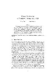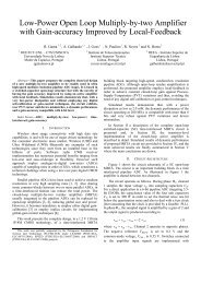
Harmonics and Flicker Analysis in Arc Furnace Power Systems
Harmonics and Flicker Analysis in Arc Furnace Power Systems
Harmonics and Flicker Analysis in Arc Furnace Power Systems

Create successful ePaper yourself
Turn your PDF publications into a flip-book with our unique Google optimized e-Paper software.
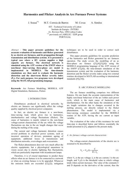
<strong>Harmonics</strong> <strong>and</strong> <strong>Flicker</strong> <strong>Analysis</strong> <strong>in</strong> <strong>Arc</strong> <strong>Furnace</strong> <strong>Power</strong> <strong>Systems</strong><br />
J. Sousa (*) M.T. Correia de Barros M. Covas A. Simões<br />
IST - Technical University of Lisbon<br />
Instituto da Energia - INTERG<br />
Av. Rovisco Pais, 1096 Lisboa Codex<br />
(*) previously at LABELEC / EDP group<br />
PORTUGAL<br />
Abstract - This paper presents guidel<strong>in</strong>es for the<br />
accurate evaluation of harmonics <strong>and</strong> flicker generated<br />
by ac electric arc furnaces, <strong>and</strong> its propagation through<br />
transmission <strong>and</strong> distribution systems. It is presented a<br />
typical case where a HV system supplies a high<br />
capacity arc furnace. The electrical network is<br />
simulated us<strong>in</strong>g the ATP version of the EMTP where a<br />
non-l<strong>in</strong>ear time-vary<strong>in</strong>g three-phase arc model is<br />
implemented <strong>in</strong> MODELS. The time-doma<strong>in</strong><br />
simulations are then used to evaluate the harmonic<br />
distortion <strong>and</strong> the short-term flicker severity <strong>in</strong>dex<br />
(P st ). For such purpose, two programs were developed<br />
us<strong>in</strong>g the MATLAB programm<strong>in</strong>g language.<br />
techniques are to be used <strong>in</strong> order to correct such<br />
disturbances.<br />
This paper presents guidel<strong>in</strong>es for accurate prediction<br />
of the harmonics <strong>and</strong> flicker generated by arc furnaces<br />
operation. The study covers the modell<strong>in</strong>g of an ac<br />
three-phase arc furnace ([3],[4],[5],[6]) us<strong>in</strong>g the<br />
MODELS programm<strong>in</strong>g language of the ATP version of<br />
the EMTP ([7],[8]), the time-doma<strong>in</strong> simulation of the<br />
transmission system <strong>and</strong> the evaluation of the harmonic<br />
distortion <strong>and</strong> the flicker severity <strong>in</strong>dex us<strong>in</strong>g two external<br />
rout<strong>in</strong>es developed <strong>in</strong> MATLAB accord<strong>in</strong>g to <strong>in</strong>ternational<br />
st<strong>and</strong>ards ([9],[10]).<br />
Keywords: <strong>Arc</strong> <strong>Furnace</strong> Modell<strong>in</strong>g, MODELS, ATP<br />
Digital Simulation, <strong>Harmonics</strong>, <strong>Flicker</strong>.<br />
I. INTRODUCTION<br />
Disturbances produced <strong>in</strong> electrical networks by<br />
electric arc furnaces can significantly affect the voltage<br />
quality supplied by electrical power companies.<br />
In fact, an electric arc furnace is a non-l<strong>in</strong>ear,<br />
time-vary<strong>in</strong>g load, which gives rise to harmonics,<br />
<strong>in</strong>terharmonics <strong>and</strong> voltage fluctuations (flicker). The<br />
cause of harmonics is ma<strong>in</strong>ly related to the non-l<strong>in</strong>ear<br />
voltage-current characteristic of the arc while the voltage<br />
fluctuations are due to the arc length changes that occur<br />
dur<strong>in</strong>g the melt<strong>in</strong>g of the scrap.<br />
The current <strong>and</strong> voltage harmonic distortion causes<br />
several problems <strong>in</strong> electrical power systems, such as<br />
<strong>in</strong>correct operation of devices, premature age<strong>in</strong>g of<br />
equipment, additional losses <strong>in</strong> transmission <strong>and</strong><br />
distribution networks, overvoltages <strong>and</strong> overcurrents.<br />
The flicker phenomenon does not very much affect the<br />
electric equipments, but a physiological uneas<strong>in</strong>ess <strong>in</strong><br />
vision occurs due to electric lightn<strong>in</strong>g flux fluctuations,<br />
which are particularly important with <strong>in</strong>c<strong>and</strong>escent lamps.<br />
Therefore, it is of crucial importance to predict these<br />
effects when an arc furnace is to be connected to a network<br />
or when an exist<strong>in</strong>g furnace is to be upgraded. Whenever<br />
the emission limits are exceeded ([1],[2]), mitigation<br />
II. ARC FURNACE MODELLING<br />
The arc furnace modell<strong>in</strong>g comprises two different<br />
features. On one h<strong>and</strong>, the accurate representation of the<br />
highly non-l<strong>in</strong>ear behaviour of the arc with<strong>in</strong> each power<br />
cycle, which is the ma<strong>in</strong> cause of harmonics <strong>and</strong><br />
<strong>in</strong>terharmonics. On the other h<strong>and</strong>, the simulation of the<br />
arc length variations due to changes occurred <strong>in</strong> the<br />
melt<strong>in</strong>g process, are directly related to the flicker<br />
phenomenon. The model is implemented via a<br />
time-vary<strong>in</strong>g resistance controlled by the MODELS<br />
rout<strong>in</strong>e of the ATP, hav<strong>in</strong>g the arc current as <strong>in</strong>put<br />
variable.<br />
The evaluation of the value of this resistance for each<br />
time-step is described below <strong>and</strong> follows essentially the<br />
model presented <strong>in</strong> [5], adapted to the present study.<br />
A. <strong>Arc</strong> furnace voltage-current characteristic<br />
The voltage-current characteristic of the electric arc is<br />
assumed to be described by<br />
C<br />
Va<br />
= Vat<br />
(l) +<br />
(1)<br />
D + I<br />
where V a is the arc voltage, I a is the arc current, l is the arc<br />
length, <strong>and</strong> V at (l) is the threshold value to which voltage<br />
tends when current <strong>in</strong>creases. The value of the constants C<br />
<strong>and</strong> D depends on the derivative of the current, thus the<br />
a
non-reversible nature of the arc (hysteresis) be<strong>in</strong>g taken<br />
<strong>in</strong>to account:<br />
⎧dIa<br />
⎪ > 0<br />
dt<br />
for ⎨<br />
⎪dIa<br />
⎪<br />
< 0<br />
⎩ dt<br />
⇒<br />
⇒<br />
C = 190 kW <strong>and</strong> D = 5kA<br />
C = 39 kW <strong>and</strong> D = 5kA<br />
Figure 1 shows the voltage-current characteristic of the<br />
arc expressed by equation (1), for the given values of C<br />
<strong>and</strong> D.<br />
Ua [V]<br />
300<br />
150<br />
0<br />
-150<br />
-300<br />
-120 0 120<br />
Ia [A]<br />
Figure 1. <strong>Arc</strong> furnace voltage-current characteristic<br />
The <strong>in</strong>troduction of the arc length variation, which is<br />
the cause of flicker, is done by the follow<strong>in</strong>g equation:<br />
Va (Ia<br />
) = KVa0<br />
(Ia<br />
)<br />
(2)<br />
where V a0 is the arc voltage correspondent to the reference<br />
length (<strong>in</strong> the present study l 0 = 39.5 cm). Thus, accord<strong>in</strong>g<br />
to equation (1), we have<br />
V<br />
a0<br />
C<br />
(Ia<br />
) = Vat<br />
(l0)<br />
+<br />
(3)<br />
D + I<br />
The threshold voltage V at is given by equation (4)<br />
a<br />
V at (l) = A + Bl<br />
(4)<br />
B. <strong>Arc</strong> length variation<br />
The rapid changes of the arc furnace current dur<strong>in</strong>g the<br />
different stages of the melt<strong>in</strong>g process are highly<br />
correlated with the arc length variation. This variation, <strong>in</strong><br />
turn, depends on the scrap, the gases produced <strong>in</strong> the<br />
process, the electrodynamic forces <strong>and</strong> the position of the<br />
electrodes. Therefore, the accurate representation of the<br />
arc length variation is difficult to achieve. In this attempt,<br />
several authors ([5],[11],[12]) have proposed both<br />
determ<strong>in</strong>istic <strong>and</strong> stochastic laws for the time-doma<strong>in</strong><br />
changes of the arc length.<br />
The determ<strong>in</strong>istic approach is based on a s<strong>in</strong>usoidal<br />
representation of the arc length variation, be<strong>in</strong>g the<br />
frequency chosen <strong>in</strong> the range typical of flicker (0.5 - 25<br />
Hz). When look<strong>in</strong>g for worst-case estimates, a frequency<br />
close to the maximum flicker perceptivity (≅10Hz) can be<br />
chosen.<br />
However, if more realistic calculations are required, the<br />
stochastic model should be used <strong>in</strong>stead. This model,<br />
although more difficult to implement, accounts for the<br />
different frequencies <strong>in</strong>volved <strong>in</strong> the voltage fluctuation<br />
generated by the arc furnaces.<br />
The time variation of the arc length is then given by<br />
l(t)<br />
= l r(t)<br />
(6)<br />
0 −<br />
where l 0 is the reference arc length (l 0 = 39.5 cm) <strong>and</strong> r(t)<br />
is b<strong>and</strong> limited (5 to 20 Hz) white noise signal with an<br />
amplitude vary<strong>in</strong>g up to the maximum arc length deviation<br />
(30.1 cm) from the reference length (39.5 cm).<br />
The time-vary<strong>in</strong>g resistance is easily obta<strong>in</strong>ed by<br />
divid<strong>in</strong>g the evaluated arc voltage V a (t) by the <strong>in</strong>put<br />
current I a (t)<br />
Va<br />
(t)<br />
R(t) = (7)<br />
I (t)<br />
a<br />
This resistance is implemented <strong>in</strong> the ATP by a type 91<br />
time-vary<strong>in</strong>g resistance controlled by MODELS.<br />
Each phase is simulated separately <strong>in</strong> order to predict<br />
unbalances <strong>and</strong> to allow for an accurate harmonic<br />
evaluation.<br />
where A represents a constant that accounts for the arc<br />
anode <strong>and</strong> cathode voltage drops (A = 40 V) <strong>and</strong> B is the<br />
per unit length voltage across the arc (B = 10 V/cm).<br />
The parameter K can then be evaluated by the ratio<br />
between the threshold voltage related to the actual arc<br />
length V at (l) <strong>and</strong> the threshold voltage of the reference arc<br />
length V at (l 0 ).<br />
K<br />
V<br />
(l)<br />
A + Bl<br />
at<br />
= =<br />
(5)<br />
Vat<br />
(l0<br />
) A + Bl0<br />
III. NETWORK DIGITAL SIMULATION<br />
The arc furnace power system represented <strong>in</strong> Figure 2<br />
is implemented <strong>in</strong> the ATP version of the EMTP.<br />
This network represents a typical system where the<br />
Po<strong>in</strong>t of Common Coupl<strong>in</strong>g (PCC) is def<strong>in</strong>ed at the<br />
send<strong>in</strong>g end of the transmission l<strong>in</strong>e (Bus 2) <strong>and</strong> the <strong>Arc</strong><br />
<strong>Furnace</strong> term<strong>in</strong>als are represented by Bus 7.
Bus 1<br />
Bus 2<br />
PCC<br />
Bus 3 B us 4 Bus 5 B us 6<br />
200<br />
150<br />
~<br />
Théven<strong>in</strong>´s<br />
equivalent<br />
Transmission l<strong>in</strong>e<br />
HV / MV<br />
Transformer<br />
Series<br />
Reactance<br />
MV / LV<br />
Transformer<br />
Connection cable<br />
Bus 7<br />
Voltage [kV]<br />
100<br />
50<br />
0<br />
-50<br />
-100<br />
<strong>Arc</strong> <strong>Furnace</strong><br />
-150<br />
Figure 2. Electrical network supply<strong>in</strong>g the arc<br />
furnace<br />
-200<br />
0 10 20 30 40 50 60 70 80 90 100<br />
Time [ms]<br />
The Théven<strong>in</strong> equivalent represents the 220 kV, 50 Hz<br />
system connected to the transmission l<strong>in</strong>e. The Théven<strong>in</strong><br />
equivalent impedance of the considered system is given by<br />
the follow<strong>in</strong>g positive, negative <strong>and</strong> zero sequence<br />
impedances:<br />
Z p = 2,17978 + j 12,261 (Ω)<br />
Z n = 2,39725 + j 12,236 (Ω)<br />
Z 0 = 2,03511 + j 9,1322 (Ω)<br />
Accord<strong>in</strong>g to the aim of the simulations, <strong>and</strong> given the<br />
required timespan <strong>and</strong> timestep, two models are used for<br />
the 220 kV transmission l<strong>in</strong>e: for the harmonic distortion<br />
evaluation, a distributed constant parameters model is<br />
implemented while a nom<strong>in</strong>al Π model is used for flicker<br />
simulations.<br />
The transmission l<strong>in</strong>e is connected to a 220 kV/30 kV,<br />
120 MVA, star/star transformer as represented <strong>in</strong> Figure 2.<br />
There is a series reactance of 2 Ω for flicker compensation,<br />
which is then, connected to a 30 kV/1.1 kV, 120 MVA,<br />
delta/star transformer. This transformer supplies the arc<br />
furnace through a cable represented by an R=0.285 mΩ,<br />
X=2.85 mΩ impedance.<br />
The arc model implemented is described <strong>in</strong> the<br />
previous section <strong>and</strong> is <strong>in</strong>cluded <strong>in</strong> the ATP simulation by<br />
a type 91 time-vary<strong>in</strong>g resistance. The arc parameters are<br />
meant to simulate an 80 MW active power arc furnace.<br />
Current [A]<br />
Voltage [kV]<br />
Figure 3. Voltage waveform at the PCC (Bus 2)<br />
600<br />
400<br />
200<br />
0<br />
-200<br />
-400<br />
-600<br />
0 10 20 30 40 50 60 70 80 90 100<br />
Time [ms]<br />
Figure 4. Current waveform at the PCC (Bus 2)<br />
1<br />
0,8<br />
0,6<br />
0,4<br />
0,2<br />
0<br />
-0,2<br />
-0,4<br />
-0,6<br />
-0,8<br />
-1<br />
0 10 20 30 40 50 60 70 80 90 100<br />
Time [ms]<br />
IV. HARMONICS<br />
The use of loads with non-l<strong>in</strong>ear voltage-current<br />
characteristics, such as the arc furnaces, result <strong>in</strong> the<br />
generation of voltage <strong>and</strong> current harmonic distortion.<br />
In fact, arc furnaces may be the most prom<strong>in</strong>ent<br />
harmonic producers because of their great capacity lumped<br />
together at one place.<br />
The simulation of the system presented <strong>in</strong> Figure 2 is<br />
carried out with a timestep of 0.15 ms to take <strong>in</strong>to account<br />
harmonics up to the order 50.<br />
Figure 3 to Figure 6 show the computed voltage <strong>and</strong><br />
current waveforms at the Po<strong>in</strong>t of Common Coupl<strong>in</strong>g (Bus<br />
2) <strong>and</strong> at the <strong>Arc</strong> <strong>Furnace</strong> (Bus 7).<br />
Current [kA]<br />
Figure 5. Voltage waveform at the <strong>Arc</strong> <strong>Furnace</strong> (Bus 7)<br />
200<br />
150<br />
100<br />
50<br />
0<br />
-50<br />
-100<br />
-150<br />
-200<br />
0 10 20 30 40 50 60 70 80 90 100<br />
Time [ms]<br />
Figure 6. Current waveform at the <strong>Arc</strong> <strong>Furnace</strong> (Bus 7)
It is clearly seen that the high harmonic distortion<br />
presented at the arc furnace (Bus 7) is greatly reduced by<br />
the transmission system.<br />
Us<strong>in</strong>g a program developed <strong>in</strong> MATLAB, based on a<br />
Fourier analysis of the time-doma<strong>in</strong> waveforms, the Total<br />
Harmonic Distortion (THD) is computed at the PCC <strong>and</strong><br />
<strong>Arc</strong> <strong>Furnace</strong> (Table 1 <strong>and</strong> Table 2). Results are presented<br />
<strong>in</strong> percentage of the 50 Hz component.<br />
timestep of 1.11 ms was used. The time-doma<strong>in</strong><br />
simulations are shown <strong>in</strong> Figure 7 <strong>and</strong> Figure 8.<br />
The program was used to predict the flicker severity<br />
associated with the voltage at PCC <strong>and</strong> at the <strong>Arc</strong> <strong>Furnace</strong>.<br />
The short-term flicker severity <strong>in</strong>dex (P st ) associated with<br />
the voltages shown, is presented <strong>in</strong> Table 3.<br />
Table 1. Voltage THD at the PCC <strong>and</strong> <strong>Arc</strong> <strong>Furnace</strong><br />
200<br />
150<br />
THD (%) - Voltage<br />
PCC (Bus 2) 0.25<br />
<strong>Arc</strong> <strong>Furnace</strong> (Bus 7) 32.53<br />
Table 2. Current THD at the PCC <strong>and</strong> arc furnace<br />
THD (%) – Current<br />
PCC (Bus 2) 2.08<br />
<strong>Arc</strong> <strong>Furnace</strong> (Bus 7) 13.26<br />
Voltage [kV]<br />
100<br />
50<br />
0<br />
-50<br />
-100<br />
-150<br />
-200<br />
0,0 0,1 0,2 0,3 0,4 0,5 0,6 0,7 0,8 0,9 1,0<br />
Time [s]<br />
Figure 7. Voltage waveform at the PCC (Bus 2)<br />
V. FLICKER<br />
1<br />
The flicker phenomenon is understood to refer to the<br />
sensation experienced by human vision when fast changes<br />
occur <strong>in</strong> the <strong>in</strong>tensity of light sources. A persistently<br />
vary<strong>in</strong>g illum<strong>in</strong>ation can cause significant annoyance <strong>and</strong>,<br />
<strong>in</strong> consequence, may lead to compla<strong>in</strong>ts of affected<br />
customers.<br />
Accord<strong>in</strong>g to extensive research work, it is known that<br />
flicker can be observed for repetitive voltage fluctuations<br />
up to a frequency where it is impossible for the eye to<br />
detect the fusion of images. This upper frequency limit can<br />
be placed approximately at 35 Hz for voltage changes less<br />
than 10 %.<br />
Moreover, the sensitivity of human visual perception<br />
has a frequency variation <strong>and</strong> exhibits a b<strong>and</strong>-pass<br />
response with maximum sensitivity between 8 <strong>and</strong> 10 Hz<br />
([10]).<br />
Bear<strong>in</strong>g <strong>in</strong> m<strong>in</strong>d that flicker mitigation techniques can<br />
be quite expensive, both for a customer with disturb<strong>in</strong>g<br />
load <strong>and</strong> for the electric utility, the International Union for<br />
Electroheat (UIE) has developed an <strong>in</strong>ternationally agreed<br />
<strong>in</strong>strument, called the flickermeter, to measure flicker <strong>and</strong><br />
established a criteria for the evaluation of flicker severity<br />
([9],[10]).<br />
In accordance to the procedure outl<strong>in</strong>ed <strong>in</strong> [9], a digital<br />
implementation of the UIE flickermeter was done us<strong>in</strong>g<br />
the MATLAB programm<strong>in</strong>g language. The<br />
implementation was validated us<strong>in</strong>g the normalised<br />
response to s<strong>in</strong>usoidal <strong>and</strong> rectangular voltage fluctuations<br />
for one unit of perceptibility presented <strong>in</strong> [10]. This<br />
program reads an <strong>in</strong>put voltage with a sample frequency of<br />
300 Hz. Therefore, when simulat<strong>in</strong>g the studied system, a<br />
Voltage [kV]<br />
0,8<br />
0,6<br />
0,4<br />
0,2<br />
0<br />
-0,2<br />
-0,4<br />
-0,6<br />
-0,8<br />
-1<br />
0,0 0,1 0,2 0,3 0,4 0,5 0,6 0,7 0,8 0,9 1,0<br />
Time [s]<br />
Figure 8. Voltage waveform at the <strong>Arc</strong> <strong>Furnace</strong> (Bus 7)<br />
Table 3. <strong>Flicker</strong> severity <strong>in</strong>dex at the PCC <strong>and</strong> <strong>Arc</strong><br />
<strong>Furnace</strong><br />
Pst<br />
PCC (Bus 2) 2.1<br />
<strong>Arc</strong> <strong>Furnace</strong> (Bus 7) 4.7<br />
VI. CONCLUSIONS<br />
The procedure presented <strong>in</strong> the paper allows for the<br />
accurate prediction of the harmonics <strong>and</strong> flicker generated<br />
by arc furnaces operation.<br />
A typical case is studied <strong>in</strong> order to show the different<br />
steps of the prediction. First, a three-phase ac electric arc<br />
model is implemented us<strong>in</strong>g the MODELS programm<strong>in</strong>g<br />
language.
Then, the time-doma<strong>in</strong> simulation of the electric power<br />
system to which the arc furnace is connected is<br />
accomplished.<br />
Two developed MATLAB programs are then used to<br />
evaluate the harmonic distortion <strong>and</strong> flicker severity<br />
associated with each location at the system.<br />
These guidel<strong>in</strong>es enables the accurate prediction of the<br />
effects of the arc furnace connection <strong>and</strong> helps <strong>in</strong> the<br />
def<strong>in</strong>ition <strong>and</strong> design of the mitigation techniques needed<br />
to correct voltage <strong>and</strong> current distortions caused by arc<br />
furnaces operation.<br />
VII. REFERENCES<br />
[1] IEC 1000-3-6, “Electromagnetic compatibility<br />
(EMC) - Part 3: Limits - Section 6: Assessment of<br />
emission limits for distort<strong>in</strong>g loads <strong>in</strong> MV <strong>and</strong> HV<br />
power systems”, Basic EMC publication, 1996.<br />
[2] IEC 1000-3-7, “Electromagnetic compatibility<br />
(EMC) - Part 3: Limits - Section 7: Assessment of<br />
emission limits for fluctuat<strong>in</strong>g loads <strong>in</strong> MV <strong>and</strong> HV<br />
power systems”, Basic EMC publication, 1996.<br />
[3] G.C. Montanari, M. Logg<strong>in</strong>i, L. Pitti, E. Tironi, D.<br />
Zan<strong>in</strong>elli, “The effects of series <strong>in</strong>ductors for flicker<br />
reduction <strong>in</strong> electric power systems supply<strong>in</strong>g arc<br />
furnaces”, IEEE/IAS Annual Meet<strong>in</strong>g, Toronto,<br />
October 1993.<br />
[4] G.C. Montanari, M. Logg<strong>in</strong>i, A. Cavall<strong>in</strong>i, L. Pitti,<br />
D. Zan<strong>in</strong>elli, “<strong>Arc</strong>-furnace model for the study of<br />
flicker compensation <strong>in</strong> electrical networks”, IEEE<br />
Transactions on <strong>Power</strong> Delivery, Vol. 9, No. 4,<br />
October 1994.<br />
[5] G.C. Montanari, M. Logg<strong>in</strong>i, A. Cavall<strong>in</strong>i, L. Pitti,<br />
“<strong>Flicker</strong> <strong>and</strong> distortion compensation <strong>in</strong> electrical<br />
plants supply<strong>in</strong>g arc-furnaces”, IEEE, 1994.<br />
[6] Cavall<strong>in</strong>i, G.C. Montanari, L. Pitti, D. Zan<strong>in</strong>elli,<br />
“ATP simulation for arc-furnace flicker<br />
<strong>in</strong>vestigation”, ETEP, Vol. 5, No. 3, May/June<br />
1995.<br />
[7] Hermann W. Dommel, “Electromagnetic Transients<br />
Program Reference Manual”, August 1986.<br />
[8] Leuven EMTP Center, “Alternative Transients<br />
Program Rule Book”, July 1987.<br />
[9] IEC 868, “<strong>Flicker</strong>meter - Functional <strong>and</strong> design<br />
specifications”, 1986.<br />
[10] UIE - Union Internationale d'Electrothermie / GDT<br />
Perturbations, “Connection of fluctuat<strong>in</strong>g loads”,<br />
July 1988.<br />
[11] G. Manchur, C.C. Erven, “Development of a model<br />
for predict<strong>in</strong>g flicker from electric arc furnaces”,<br />
IEEE Transactions on <strong>Power</strong> Delivery, Vol. 7, No.<br />
1, January 1992.<br />
[12] Sr<strong>in</strong>ivas Varadan, Elham B. Makram, Adly A.<br />
Girgis, “A new time doma<strong>in</strong> voltage source model<br />
for an arc furnace us<strong>in</strong>g EMTP”, IEEE<br />
Transactions on <strong>Power</strong> Delivery, Vol. 11, No. 3,<br />
July 1996.