Download Service Manual - Quietside
Download Service Manual - Quietside
Download Service Manual - Quietside

Create successful ePaper yourself
Turn your PDF publications into a flip-book with our unique Google optimized e-Paper software.
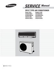
WIRED REMOTE CONTROLLER<br />
Basic : MWR-WS00<br />
Model : MWR-WH00<br />
Model code : MWR-WH00<br />
WIRED REMOTE CONTROLLER<br />
CONTENTS<br />
1. Precautions<br />
2. Product Specifications<br />
3. Disassembly and Reassembly<br />
4. Troubleshooting<br />
5. Exploded Views and Parts List<br />
6. PCB Diagram<br />
MWR-WH00<br />
7. Schematic Diagram<br />
Refer to the service manual in the GSPN(see the rear cover) for the more information.
Section 0<br />
Contents<br />
1. Precautions ......................................................................................................................................................................................................... 1-1<br />
1-1 Precautions for the <strong>Service</strong> ............................................................................................................................................................... 1-1<br />
1-2 Precautions for the Safety ................................................................................................................................................................. 1-1<br />
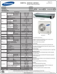
2. Product Specifications ...................................................................................................................................................................... 2-1<br />
2-1 The Feature of Product ....................................................................................................................................................................... 2-1<br />
2-1-1 Feature .................................................................................................................................................................................................. 2-1<br />
2-1-2 Changes in Comparison to Basic Model ............................................................................................................... 2-2<br />
2-2 The Structure of Product .................................................................................................................................................................... 2-3<br />
2-3 Product Specifications .......................................................................................................................................................................... 2-4<br />
2-3-1 Using Environment ................................................................................................................................................................... 2-4<br />
2-3-2 Feature deployment specification ............................................................................................................................. 2-5<br />
2-3-3 Option Switch Setting ........................................................................................................................................................... 2-7<br />
2-4 Installation ....................................................................................................................................................................................................... 2-8<br />
2-4-1 Installing the Power Cables inside of Indoor Unit ....................................................................................... 2-8<br />
2-4-2 Installing the Wired Remote Controller ................................................................................................................ 2-9<br />
2-5 Accessory and Option Specifications ................................................................................................................................... 2-10<br />
2-5-1 Accessories ....................................................................................................................................................................................... 2-10<br />
3. Disassembly and Reassembly .............................................................................................................................................. 3-1<br />
4. Troubleshooting ......................................................................................................................................................................................... 4-1<br />
4-1 What to Check before Diagnosis ................................................................................................................................................ 4-1<br />
4-1-1 Wired Remote Controller Error Display ................................................................................................................. 4-1<br />
4-1-2 Wired Remote Controller Error List ........................................................................................................................... 4-2<br />
4-2 How to Take Measures for Each Symptom ....................................................................................................................... 4-3<br />
4-2-1 When the LCD Display Doesn’t Show ..................................................................................................................... 4-3<br />
4-2-2 When Communication Error Occurs or Communication is Impossible ................................. 4-4<br />
5. Exploded Views and Parts List ............................................................................................................................................ 5-1<br />
6. PCB Diagram ....................................................................................................................................................................................................... 6-1<br />
7. Schematic Diagram ................................................................................................................................................................................ 7-1<br />
Samsung Electronics 1
1. Precautions<br />
1-1 Precautions for the <strong>Service</strong><br />
● Use the standard parts when replacing the electric parts.<br />
- Confirm the model name, rated voltage, rated current of the electric parts.<br />
● Repair the disconnection of HARNESS securely when repairing the break down.<br />
- If there is any connection error, it causes an abnormal noise and incorrect operation.<br />
● In case that you assemble or disassemble the products with laying it on the side, do work on the work cloth.<br />
- If not, the exterior of products can be scratched.<br />
● Remove dust and foreign materials from harness, connection part, and inspection part thoroughly when repairing the<br />
break down.<br />
- It protects the danger of fire such as tracking and short.<br />
● Check the assembly status of parts after repairing the break down.<br />
- It should be same as the status before repairing.<br />
1-2 Precautions for the Safety<br />
● Do not pull any electric wires and do not touch an auxiliary power switch with a wet hand.<br />
- There is a danger of electric shock or fire.<br />
● In case any wire or power plug has been damaged, replace it to eliminate any possible danger.<br />
● Do not bend the power cord by force and do not put any heavy object on the power cord.<br />
- There is a danger of electric shock or fire.<br />
● Ground the product if necessary.<br />
- Be sure to ground the product if there is any danger of electric leakage due to water or moisture.<br />
● Be sure to turn off the auxiliary power switch or pull out the power plug during replacement or repair of electric parts.<br />
- There is a danger of electric shock.<br />
1-1 Samsung Electronics
2. Product Specifications<br />
2-1 The Feature of Product<br />
2-1-1 Feature<br />
■ Basic wired remote controller with stylish design<br />
Master wired remote controller<br />
Slave wired remote controller<br />
∙∙∙<br />
Maximum 2 wired remote controller<br />
can control as a group.(Master/Slave)<br />
The wired remote controller can control<br />
maximum 16 indoor units as a group.<br />
1) PBA : MAIN PBA<br />
- Samsung 3F4A1H<br />
- FRAM<br />
- FSTN<br />
- Wrong wiring protection Relay applied<br />
- Diode for multiple recognition of buttons applied<br />
2) Application S/W<br />
- Basic Control<br />
- On-time, Off-time control<br />
- Error Display<br />
- User-setting function, <strong>Service</strong> mode<br />
3) Commercialization materials: Box, Label, <strong>Manual</strong><br />
Samsung Electronics 2-1
Product Specifications<br />
2-1-2 Changes in Comparison to Basic Model<br />
Item Basic Model (MWR-WS00) Development Model (MWR-WH00) Remarks<br />
1) Switch rubber components<br />
changed<br />
Ass'y Case<br />
2) Switch plastic components<br />
improvement<br />
3) Cover hinge improvement<br />
1) MCU changed<br />
- MB90F423(Fujitsu)<br />
- S3F4A1H(Samsung)<br />
Ass'y PCB<br />
2) 485 communication Relay<br />
added<br />
- Wrong wiring protection<br />
3) MCU download port added<br />
4) JIG POINT added<br />
- ICT JIG improvement<br />
5) Button Diode added<br />
- Integrated key function<br />
improvement<br />
1) LCD changed<br />
Etc.<br />
2) Button Inlay development<br />
2-2 Samsung Electronics
2-2 The Structure of Product<br />
■ Dimensional Drawing<br />
(Unit: mm)<br />
122<br />
50 23<br />
120<br />
■ Exterior structure<br />
Protection relay against<br />
wrong wiring<br />
Micom download connector<br />
Main MICOM<br />
Power/communication<br />
connector<br />
[PBA structure]<br />
<br />
<br />
CASE<br />
LCD<br />
Dome type button<br />
Rubber type button<br />
<br />
<br />
<br />
<br />
<br />
<br />
<br />
<br />
<br />
<br />
<br />
<br />
<br />
<br />
<br />
<br />
[Exterior structure]<br />
<br />
<br />
<br />
<br />
<br />
<br />
<br />
<br />
<br />
<br />
<br />
[Software structure]<br />
Samsung Electronics 2-3
2-3 Product Specifications<br />
2-3-1 Using Environment<br />
Classification No. Item Specification Remarks<br />
1 Area Europe<br />
General<br />
Refer to the user's<br />
2 Type Wall-mounted type indoor unit remote control device<br />
requirements<br />
manual<br />
3 Accessory Contact service center<br />
1<br />
Standard<br />
temperature/ 15- 25˚C , 35 - 65 %<br />
Installation<br />
requirements<br />
2<br />
humidity<br />
Temperature 0˚C~40˚C (for indoor only)<br />
3 Humidity Humidity 30%RH~90%RH(Condition: No dew condensate)<br />
Power 1 Input 12VDC/500mA<br />
Installation 2 Space requirements Installing on the wall using the bracket<br />
1 Installer Qualified technician<br />
2 Open Follow the instructions.<br />
Delivery<br />
3 Check delivery<br />
•Check according to the CHECK SHEET. Repair the inferior goods.<br />
• Follow the user's manual for using method, using condition and precautions.<br />
If a problem occurs, you will be supported by the service center.<br />
Installation<br />
method<br />
1 - Refer to the installation manual<br />
Etc. 1 - Make sure to refer to the installation manual and user's manual<br />
2-4 Samsung Electronics
Product Specifications<br />
2-3-2 Feature deployment specification<br />
1) Max. quantity of connected units : Max. 16 units of indoor units can be connected.<br />
2) Master and Slave connection is possible between MWR-WH00s for connecting 1 indoor unit.<br />
3) Master and Slave connection is possible between MWR-WH00 and MWR-WE00.<br />
• MWR-WH00(Master) – MWR-TH00,TH01(Slave):Connection is impossible<br />
• MWR-WH00(Master) – MWR-WS00(Slave):Connection is impossible<br />
• MWR-WH00(Master) – MWR-SH00(Slave):Connection is impossible<br />
• MWR-WH00(Master) – MWR-VH00, VH01, VH02 (Slave): Connection in impossible<br />
• Against the above is same too.<br />
4) Special function<br />
• Auto stop function : Turn off the indoor unit after set time has passed since any button on the remote controller was last pressed.<br />
• Temperature limit : Set upper limit or lower limit of temperature<br />
• Part locking of the button : , , , and buttons<br />
5) <strong>Service</strong> mode specification<br />
a) Monitoring and setting the indoor unit option code<br />
b) Monitoring the indoor unit’s main or group address<br />
c) Monitoring the indoor unit cycle data<br />
d) Monitoring and setting the indoor temperature compensation for the wired remote controller<br />
e) Monitoring the RPM compensation<br />
f) Monitoring the EEV Step for the stopped indoor unit during heating mode<br />
g) Monitoring the filter time setting<br />
h) Monitoring the temperature compensation value under heating mode<br />
i) Checking the centralized control usage<br />
j) Checking the drain pump usage<br />
k) Checking the electric heater usage<br />
l) Checking the water coil usage<br />
m) Checking the external control usage<br />
n) Checking the connected indoor unit quantity<br />
o) Checking the wired remote controller PCB settings<br />
p) Checking the wired remote controller software version<br />
6) Error display<br />
• Indoor unit error<br />
• Outdoor unit error<br />
• Wired remote controller error<br />
Samsung Electronics 2-5
Product Specifications<br />
7) Buttons and display specification<br />
No. Button Description<br />
1 Start or Stop the operation<br />
2 Set temperature up<br />
3 Set temperature down<br />
4 Fan speed (Auto → Low → Medium → High → Auto)<br />
5 Set the desired time to turn on indoor unit<br />
6<br />
7<br />
• Set the desired time to turn off indoor unit<br />
• Hold down(3 sec) : Enter the User-setting mode<br />
• Press : Check the input<br />
• Hold down : Lock the buttons<br />
8 Cancel the set on/off-timer<br />
9 Select the operation mode (Auto → Cool → Dry → Fan → Heat → Auto)<br />
10 Operate the quiet mode<br />
11 Turn on or off the air swing<br />
12 Operate the sleep mode<br />
13 When the is on, Clean the filter and turn off the display pressing the filter reset button.<br />
14 Display current room temperature.<br />
15 + Hold down(5 sec) : Reset the wired remote controller<br />
16 + Hold down(5 sec) : Enter the <strong>Service</strong> mode<br />
2-6 Samsung Electronics
Product Specifications<br />
2-3-3 Option Switch Setting<br />
<br />
<br />
<br />
[Default setting]<br />
DIP switch No. Port Off On<br />
SW1 P2.6/#76 Cooling and Heating Cooling only<br />
SW2 P2.7/#77 Allow the wireless remote controller Disable the wireless remote controller<br />
SW3 P2.8/#78 Master remote controller Slave remote controller<br />
SW4 P2.9/#79 Temperature display : ˚C Temperature display : ˚F<br />
SW5<br />
P2.10/#80<br />
Use the indoor unit temperature sensor for the<br />
indoor unit control.<br />
Use the wired remote controller temperature sensor<br />
for the indoor unit control.<br />
SW6 P2.11/#81 -<br />
Use the average of the indoor unit sensor and<br />
the wired remote controller sensor for the indoor<br />
unit control.<br />
SW7 P2.12/#82 Auto mode enable Auto mode disable<br />
SW8 P2.13/#83 - -<br />
Samsung Electronics 2-7
2-4 Installation<br />
2-4-1 Installing the Power Cables inside of Indoor Unit<br />
This is an explanation of power supply cable and communication cable. Make sure that you read this thoroughly before<br />
installation.<br />
■ Connector type cable connection<br />
Indoor unit terminel block<br />
AC Power supply<br />
Indoor<br />
unit PCB<br />
White<br />
Check the wire colors.<br />
The wires are color-coded<br />
White<br />
White 2P<br />
(2.5 pitch)<br />
White 2P<br />
(2.5 pitch)<br />
F3<br />
Black<br />
Red<br />
Power cable for the<br />
indoor unit<br />
Black<br />
Red<br />
F4<br />
Blue<br />
Communication cable for<br />
the indoor unit<br />
(COM2)<br />
Blue<br />
Blue 2P<br />
(2.5 pitch)<br />
Blue 2P<br />
(2.5 pitch)<br />
■ Terminal type cable connection<br />
Indoor unit terminel block<br />
AC Power supply<br />
Indoor<br />
unit PCB<br />
White<br />
Check the wire colors.<br />
The wires are color-coded<br />
White<br />
White 2P<br />
(2.5 pitch)<br />
White 2P<br />
(2.5 pitch)<br />
Black<br />
Red<br />
Power cable for the<br />
indoor unit<br />
Red<br />
Black<br />
Blue<br />
Communication cable for<br />
the indoor unit<br />
(COM2)<br />
Blue<br />
Blue 2P<br />
(2.5 pitch)<br />
Blue 2P<br />
(2.5 pitch)<br />
• 1 way cassette indoor unit does not contain the power cable. In this case, use the power cable inside of the indoor unit which is provided<br />
with the wired remote controller.<br />
2-8 Samsung Electronics
Product Specifications<br />
2-4-2 Installing the Wired Remote Controller<br />
1) Open the wired remote controller by pushing up the top cover of the remote controller while holding the rear cover<br />
firmly.<br />
• The wired remote controller opens in the way of slide.<br />
2) Install the rear cover of the wired remote controller on the wall with the supplied screws.<br />
After that, arrange the power cables on rear side of the front cover.<br />
more than 30mm<br />
more than 60mm<br />
screw<br />
hole<br />
rear cover<br />
front cover<br />
Before fixing the rear cover,<br />
clear 30mm of space on the top<br />
and 60mm on the right side.<br />
Fasten the screw in the<br />
screw hole.<br />
3) Connect the yellow and orange wires from the wired remote controller to the V1 and V2 terminal of the indoor unit.<br />
Connect the red and blue wires to the F3 and F2.<br />
Connector type cable connection<br />
- Using the provided indoor unit communication<br />
cable, connect to the housing.<br />
Terminal type cable connection<br />
F3<br />
F4<br />
Tighten the<br />
cable with the<br />
wire joint<br />
(accessories)<br />
tightly.<br />
Housing<br />
Power cable<br />
(V1, V2)<br />
Indoor unit<br />
Power cable<br />
(V1, V2)<br />
Indoor unit<br />
Communication<br />
cable(F3, F4)<br />
Wired remote<br />
controller<br />
Communication<br />
cable(F3, F4)<br />
Wired remote<br />
controller<br />
4) Reassemble the wired remote controller.<br />
• When you reassemble the wired remote controller, match the grooves on the left side.<br />
Samsung Electronics 2-9
2-5 Accessory and Option Specifications<br />
2-5-1 Accessories<br />
Image Name Code Quantity Remarks<br />
Wired remote controller<br />
MWR-WH00<br />
DB93-08033B 1<br />
Cable tie DB65-10088B 2<br />
Cable clamp DB65-10074E 4<br />
M4X16 screw 6002-000474 5<br />
Power cable for indoor unit DB39-00221A 1<br />
Communication cable for indoor unit DB39-00933A 1<br />
Wire joint DB39-90020A 4<br />
User's manual DB98-31219A 1<br />
Installation manual DB98-31218A 1<br />
2-10 Samsung Electronics
3. Disassembly and Reassembly<br />
No. Image Procedure<br />
1 To disassemble the front and rear cover, hold the front cover firmly and push<br />
the rear cover downward.<br />
If you pull the rear cover to the front instead of pulling it to<br />
downward, it can be damaged.<br />
2 Separate the power connector.<br />
3 Loosen three screws and separate the PBA.<br />
4 Separate the rubber button.<br />
Samsung Electronics 3-1
Disassembly and Reassembly<br />
No. Image Procedure<br />
5 Separate the button.<br />
6 Separate the door.<br />
3-2 Samsung Electronics
4. Troubleshooting<br />
4-1 What to Check before Diagnosis<br />
4-1-1 Wired Remote Controller Error Display<br />
The error codes of wired remote controller, indoor unit,<br />
outdoor unit are displayed on the LCD display.<br />
■ When the indoor/outdoor unit error occurs<br />
Main(COM1) address(A) of the indoor/outdoor unit where error occurred and error code are<br />
displayed in turns.<br />
Ex) 101 error occurred in #28 indoor unit<br />
Indoor unit<br />
■ When the wired remote controller error occurs<br />
Error code is displayed only. (Address will not be displayed.)<br />
[LCD display]<br />
Ex) 601 error occurred in the wired remote controller<br />
Samsung Electronics 4-1
Troubleshooting<br />
4-1-2 Wired Remote Controller Error List<br />
Error Code Explanation Remarks<br />
• Master error of several units.<br />
• Error occurs when 2 wired remote controllers are set as Master and installed in one<br />
communication cable.<br />
If communication cable is connected to opposite polarity, detection is impossible.<br />
• Error is detected only in Master wired remote controller.<br />
• Error of independent ERV installation.<br />
• When ERV is installed without an indoor unit.<br />
• Error is detected only in Master wired remote controller.<br />
• Slave wired remote controller installation error.<br />
• When 2 slave wired remote controllers are installed.<br />
• When 1 wired remote controller and 2 slave ERV remote controllers are installed together.<br />
High Priority<br />
Communication Tracking Error.<br />
• Mater ↔ Slave wired remote controller communication error.<br />
• Error is detected only in Slave wired remote controller.<br />
Wired remote controller ↔ indoor unit/ERV communication error.<br />
Temperature OPEN/SHORT error.<br />
FRAM READ/WRITE error.<br />
Low Priority<br />
• Mixed installation of Celsius(°C)/Fahrenheit(°F) indoor unit error.<br />
• Error occurs when indoor units with Celsius(°C)/Fahrenheit(°F) settings are installed together.<br />
• Error is detected only in Master wired remote controller.<br />
• Celsius(˚C)/Fahrenheit(˚F) setting error of the wired remote controller<br />
• Error occurs when the indoor unit is set as Celsius and the wired remote controller is set as<br />
Fahrenheit or vise versa.<br />
• Change the setting of DIP switch 4 when the 620 error occurs.<br />
Refer to the installation manual of each device(Indoor/Outdoor Unit) for error code references.<br />
4-2 Samsung Electronics
4-2 How to Take Measures for Each Symptom<br />
4-2-1 When the LCD Display Doesn't Show<br />
Start<br />
Are the ASS'Y PBA(DB93-08787A) and<br />
power cable connected properly?<br />
No<br />
Check the connection of ASS'Y PBA<br />
and power cable.<br />
Yes<br />
Is the voltage of CN02's both ends(1,2) 12V?<br />
No<br />
Change ASS'Y CONNECTOR<br />
wire (DB93-04023D)<br />
Yes<br />
Change ASS'Y PBA(DB93-08787A)<br />
End<br />
Samsung Electronics 4-3
Troubleshooting<br />
4-2-2 When Communication Error Occurs or Communication is Impossible<br />
Start<br />
Are the ASS'Y PBA(DB93-08787A) and<br />
power cable connected properly?<br />
No<br />
Check the connection of ASS'Y PBA<br />
and power cable.<br />
Yes<br />
Is the resistance of between<br />
the both ends of ASS'Y PBA(DB93-08787A)<br />
C302 higher than 200KΩ?<br />
No<br />
Change ASS'Y PBA<br />
Yes<br />
Is the resistance of between<br />
the top part of ASS'Y PBA(DB93-08787A)<br />
C302 and GND higher than 100KΩ?<br />
No<br />
Change ASS'Y PBA<br />
Yes<br />
Is the resistance of between<br />
the bottom part of ASS'Y PBA(DB93-08787A)<br />
C302 and GND higher than 100KΩ?<br />
No<br />
Change ASS'Y PBA<br />
Yes<br />
Check the indoor units' communication which is<br />
connected to the wired remote controller<br />
(Not the problem of the wired remote controller)<br />
End<br />
4-4 Samsung Electronics
5. Exploded Views and Parts List<br />
<br />
<br />
<br />
<br />
<br />
<br />
<br />
<br />
<br />
■ Parts list<br />
No.<br />
Code<br />
Name Specification Q'TY<br />
Remark<br />
1 DB64-01522A DOOR REMOCON ABS, 1.5T, 120mm, 50mm 1 SA<br />
2 DB64-01525A WINDOW DISPLAY PC, 0.5T, 55mm, 95mm, color no 1 SNA<br />
3 DB64-01528F INLAY_BUTTON PC, T0.5, W38.2, H112.2, Silver 1 SNA<br />
4 DB63-01457A COVER CASE TOP ABS, 2.0T, W112, H120, Cream white 1 SNA<br />
5 DB64-01526A KNOB BUTTON ABS, 2.0T, 20mm, 90mm 1 SNA<br />
6 DB73-00537A RUBBER BUTTON Silicon, W109.91, H59, 50, D5.3, White 1 SNA<br />
7 DB93-08787A ASS'Y PCB MAIN-SOLUTION MWR-WH00, Wired remote controller, PBA 1 SA<br />
8 DB63-02291A COVER CASE BOTTOM ABS, T2, W120, L114 1 SA<br />
9 DB93-04023D ASS'Y CONNECTOR WIRE wire, Wired remote controller 1 SNA<br />
Samsung Electronics 5-1
6. PCB Diagram<br />
11 1 2 3 4 5 6<br />
10<br />
9<br />
8<br />
7<br />
1<br />
Diode 2 Relay 3 5V Regulator 4 MICOM<br />
Non-polar power<br />
Prevent wrong wiring between<br />
communication and Power cable<br />
5V Power supply<br />
S3F4A1H Micro controller<br />
5<br />
Switch 6 Temperature sensor<br />
7 8<br />
connector<br />
Select various service options of<br />
remote controller<br />
Temperature sensor Program download<br />
connector for development<br />
9 Program download<br />
10 485 Communication part 11 Power and communication<br />
connector for service<br />
485 Communication with the<br />
indoor unit<br />
connector<br />
6-1 Samsung Electronics
MEMO<br />
Samsung Electronics 6-2
7. Schematic Diagram<br />
Power Circuit Part (DC12V)<br />
485 Communication Part<br />
Switch Part<br />
Reset IC Part<br />
Temperature Sensor Part<br />
LCD Part<br />
FRAM Part<br />
This Document can not be used without Samsung’s authorization.<br />
Samsung Electronics 7-1
This <strong>Service</strong> <strong>Manual</strong> is a property of Samsung Electronics Co., Ltd.<br />
Any unauthorized use of <strong>Manual</strong> can be punished under applicable<br />
International and/or domestic law.<br />
© Samsung Electronics Co., Ltd. Dec. 2009.<br />
Printed in Korea.<br />
Code No. DB98-31329A(1)