Service Manual - Quietside
Service Manual - Quietside
Service Manual - Quietside
- No tags were found...

You also want an ePaper? Increase the reach of your titles
YUMPU automatically turns print PDFs into web optimized ePapers that Google loves.
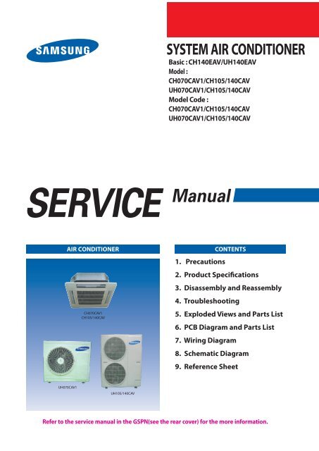
Contents11. Precautions ........................................................................................................................................ 1-11-1 Installing the air conditioner .......................................................................................................... 1-11-2 Power supply and circuit breaker ................................................................................................. 1-11-3 During operation .............................................................................................................................. 1-21-4 Disposing of the unit ....................................................................................................................... 1-21-5 Others ................................................................................................................................................. 1-212. Product Specifications ............................................................................................................... 2-12-1 The Feature of Product .................................................................................................................... 2-12-2 Product Specifications ..................................................................................................................... 2-22-3 The Comparative Specifications of Product ............................................................................... 2-52-4 Accessory and Option Specifications ............................................................................................ 2-63. Disassembly and Reassembly .............................................................................................. 3-13-1 Indoor Unit ......................................................................................................................................... 3-23-2 Outdoor Unit ..................................................................................................................................... 3-114. Trouble shooting ........................................................................................................................... 4-14-1 Indoor Display Error and Check Method ................................................................................................. 4-14-2 Outdoor LED Error Display and Check Method .................................................................................... 4-44-3 Setting Option Setup Method ...................................................................................................................... 4-54-4 Items to be checked first ................................................................................................................................. 4-164-5 Fault Diagnosis by Symptom ........................................................................................................................ 4-174-6 PCB Inspection Method .................................................................................................................................. 4-344-7 Main Part Inspection Method ....................................................................................................................... 4-365. Exploded Views and Parts List ............................................................................................. 5-15-1 Indoor Unit ......................................................................................................................................... 5-15-2 Panel ................................................................................................................................................... 5-45-3 Outdoor Unit ...................................................................................................................................... 5-65-4 Assy control out .................................................................................................................................. 5-106. PCB Diagram and Parts list ...................................................................................................... 6-16-1 PCB Diagram ..................................................................................................................................... 6-16-2 PCB Parts list ..................................................................................................................................... 6-87. Wiring Diagram .............................................................................................................................. 7-118. Schematic Diagram ...................................................................................................................... 8-18-1 Indoor Unit ......................................................................................................................................... 8-18-2 Outdoor Unit .................................................................................................................................... 8-29. Reference Sheet ............................................................................................................................. 9-19-1 Refrigerating Cycle Diagram .......................................................................................................... 9-19-2 Index for Model Name ..................................................................................................................... 9-2CH£ª£ª£ªCAV_USA_30520_SM_N.indd 2 2009-2-19 11:08:41
1. Precautions1-1 Installing the air conditioner Users should not install the air conditioner by themselves.Ask the dealer or authorized company to install the air conditioner except thewindow-type air conditioner in U.S.A and Canada. If you don’t install the air conditioner properly, it may cause a fire, a water leakageor an electric shock. You must install the air conditioner according to the national wiring regulationsand safety regulations. Install the indoor unit higher than 2.5m from the floor to avoid the injurycaused by the operation of the fan. (except the window-type air conditioner) The manufacturer is not responsible for any accidents or injury caused by anincorrect installation.When installing the built-in type air conditioner, keep all electric cables such asthe power cable and the connection cord in pipes, ducts, or cable channels toprotect them from the danger of impact or any other incidents.dangerousAvoid Dangerous Contact1-2 Power supply and circuit breaker If the power cord of the air conditioner is damaged, it must be replaced by the manufactureror a qualified person in order to avoid a hazard. The air conditioner must be plugged into an independent circuit if applicable or connectthe power cable to the auxiliary circuit breaker.An all pole disconnection from the power supply must be incorporated in thefixed wiring with a contact opening of >3mm. Do not extend an electric cord to the air conditioner. The air conditioner must be plugged in after you complete the installation.No Tapping and No Extension CordsSamsung Electronics 1-1CH£ª£ª£ªCAV_USA_30520_SM_N.indd 1 2009-2-18 17:32:24
1-3 During operation Do not repair the air conditioner at your discretion.It is recommended to contact a service center directly. Never spill any kind of liquid on the air conditioner.If this happens, turn off the air conditioner and contact an authorized service center. Do not insert anything between the airflow blades to prevent damage of the innerfan and consequent injury. Keep children away from the air conditioner. Do not place any obstacles in front of the air conditioner. Do not spray any kind of liquid into the indoor unit. If this happens, turn off the airconditioner and contact a service center. Make sure that the air conditioner is well ventilated at all times:Do not place a cloth or other materials over it. Remove the batteries if you don’t use the remote control for a long time. (If applicable) Use the remote control within 7 meters from the indoor unit. (If applicable)No children Nearby1-4 Disposing of the unit Before throwing out the air conditioner, remove the batteries from the remote control. When you dispose of the air conditioner, consult your dealer. If pipes are removed incorrectly, refrigerant may blow out and causeair pollution. When it contacts with your skin, it can cause skin injury. The package of the air conditioner should be recycled or disposed of properly for environmental reasons.1-5 Others Never store or load the air conditioner upside down or sideways to prevent the damage to the compressor. Young children or infirm persons should be always supervised when they use the air conditioner. Max current is measured according to IEC standard for safety. Current is measured according to ISO standard for energy efficiency.1-2 Samsung ElectronicsCH£ª£ª£ªCAV_USA_30520_SM_N.indd 2 2009-2-18 17:32:24
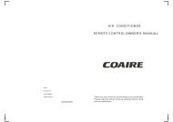
2. Product Specifications2-1 The Feature of Product Built-in Cassette TypeAfter installed, the air conditioner can be harmonized with a room interior. High Performance & Energy SavingWith the advanced BLDC inverter technology, it makes a room cool with highly energy saving and arises the efficiency of airconditioner. Long Piping(Length & Height)It can give the benefit to the installers and aries the reliability of the air conditioner. Long Ambient Operation(In Low Temperature)It can arise the reliability and the capacity of the air conditioner, especially operated in low temperature. Eco-friendly Product(Lead-Free, RoHS, WEEE)Samsung Electronics 2-1CH£ª£ª£ªCAV_USA_30520_SM_N.indd 1 2009-2-18 17:32:24
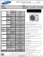
2-2 Product SpecificationsItemTypeSizePowerPerformanceModelCH070CAV1UH070CAV1Indoor UnitOutdoor UnitCassette-typeCooling(MIN/STD/MAX) Btu/h 7,500/24,000/28,500Heating(MIN/STD/MAX) Btu/h 6,500/27,000/37,000Dehumidifying gal/h 0.71Air VolumeCooling773/685/646 1413ft³/min(H/M/L)Heating 788/766/675 1413NoiseCooling45 60dB(H/M/L)Heating 45 60Cooling17.0SEER/HSPF RatioBtu/hHeating 9.9Power ph/V/Hz 1/208-230V~/60Hz2,250Power Consumption Cooling WHeating 2,300Cooling10.2Operating CurrentAHeating 10.3Cooling95Power Factor%Heating 95mm 840x218x840 880x798x310Outer Dimension WXHXDinch 33.1x8.6x33.1 34.6x31.4x12.2Weight(Net) lb 68 126ModelG8T260FUAEWCompressorMotor TypeTWIN BLDCPipingOil TypePOEType Turbo Fan PropellerBlowerType Resin ALMotorRated Output W 35 130Liquid mm(inch)xL(ft) 6.35(1/4)x16.4Pipe O.D SizeGas mm(inch)xL(ft) 15.88(5/8)x16.4Connection MethodFlareHeight ft Max.98.4BetweenPipe Length ft Max.164.0Heat Exchanger 2ROW 8STEP 2ROW 36STEPRefrigerant Control UnitEEVFreezer Oil Capacity gal 0.18Refrigerant to Change(R410A) oz 67.0(0.32oz/ft)Protection Device(OLP)InternalCooling Test Condition INDOOR UNIT : DB80.6˚F WB66.2˚F OUTDOOR UNIT : DB95˚F WB75.2˚FHeating Test Condition INDOOR UNIT : DB68˚F WB59˚F OUTDOOR UNIT : DB44.6˚F WB42.8˚F2-2 Samsung ElectronicsCH£ª£ª£ªCAV_USA_30520_SM_N.indd 2 2009-2-18 17:32:25
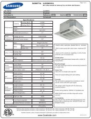
ItemTypeSizePowerPerformanceModelCH105CAVUH105CAVIndoor unitOutdoor unitCassette-typeCooling(MIN/STD/MAX) Btu/h 11,000/36,000/41,000Heating(MIN/STD/MAX) Btu/h 9,200/38,000/50,000Dehumidifying gal/h 4.76Air VolumeCooling784/639/509 3885ft³/min(H/M/L)Heating 908/752/607 3885NoiseCooling48 66dB(H/M/L)Heating 49 66Cooling15.5SEER/HSPF RatioBtu/hHeating 9.5Power ph/V/Hz 1/208-230V~/60HzCooling3,400Power ConsumptionWHeating 3,400Cooling14.5Operating CurrentAHeating 14.7Cooling92Power Factor%Heating 92mm 840x298x840 932X1128X375Outer Dimension WXHXDinch 33.1x9.1x33.1 36.7X44.4X14.8Weight(Net) lb 64 198ModelG5T360FUAEKCompressorMotor Type TWIN BLDCPipingOil TypeFREOLα 68ES-T Ze-GLES RB68-EPType TURBO-FAN PropellerBlowerType AL ALMotorRated Output W 100 165Liquid mm(inch)xL(ft) 9.52(3/8")x24.6Pipe O.D SizeGas mm(inch)xL(ft) 15.88(5/8")x24.6Connection MethodFlareHeight ft Max.98.4BetweenPipe Length ft Max.246.1Heat Exchanger 2ROW 13STEP 2ROW 52STEPRefrigerant Control UnitEEVFreezer Oil Capacity gal 0.29Refrigerant to Change(R410A) oz 98.8(0.43oz/ft)Protection Device(OLP)InternalCooling Test Condition INDOOR UNIT : DB80.6˚F WB66.2˚F OUTDOOR UNIT : DB95˚F WB75.2˚FHeating Test Condition INDOOR UNIT : DB68˚F WB59˚F OUTDOOR UNIT : DB44.6˚F WB42.8˚FSamsung Electronics 2-3CH£ª£ª£ªCAV_USA_30520_SM_N.indd 3 2009-2-18 17:32:25
2-3 The Comparative Specifications of ProductItemDevelopment ModelCH140CAV/UH140CAVComparative ModelCH140EAV/UH140EAVOutdoor UnitDesignIndoor UnitNet WeightOuter Dimension(WidthxHeightxDepth)NoiseIndoor Unit 64lb 29.0kgOutdoor Unit 207lb 98.0kgIndoor Unit 33.1x9.1x33.1(inch) 33.1x9.1x33.1(inch)Outdoor Unit 36.7x44.4x14.8(inch) 36.7x44.4x14.8(inch)Indoor Unit 50dB 45dBOutdoor Unit 66dB 60dBItemDevelopment ModelCH070CAV1/UH070CAV1Comparative ModelCH070EAV1/UH070EAV1Outdoor UnitDesignIndoor UnitNet WeightOuter Dimension(WidthxHeightxDepth)NoiseIndoor Unit 68lb 68lbOutdoor Unit 126lb 126lbIndoor Unit 33.1x8.6x33.1(inch) 33.1x8.6x33.1(inch)Outdoor Unit 34.6x31.4x12.2(inch) 34.6x31.4x12.2(inch)Indoor Unit 45dB 45dBOutdoor Unit 60dB 60dBSamsung Electronics 2-5CH£ª£ª£ªCAV_USA_30520_SM_N.indd 5 2009-2-18 17:32:32
2-4 Accessory and Option SpecificationsAccessoriesItem Descriptions Code-No. Q'TY RemarkPad install DB69-01490C 1Insulation drain in DB62-03440L 1Insulation drain out DB62-03439H 1Insulation install outlet DB72-00143D 1Insulation install inlet DB72-00143E 1Insulation out DB62-03439J 2Cable-tie DB65-10088C 8IndoorUnitFlexible hose DB94-01500A 1Pad stopper DB69-00165A 1Safety net DB63-01480A 1M4x12 tapped Screw 6002-000213 4Installation manual DB98-30519A 1<strong>Service</strong> <strong>Manual</strong> DB98-30520A 1Blacket Conduit DB61-03709A 12-6 Samsung ElectronicsCH£ª£ª£ªCAV_USA_30520_SM_N.indd 6 2009-2-18 17:32:33
Accessories(cont.)Item Descriptions Code-No. Q'TY RemarkDrain Plug DB67-00477A 1Cap Drain DB63-10355C 1Rubber bracket Wire DB73-00218A 2OutdoorUntiNut Flare DB60-30010B 1Samsung Electronics 2-7CH£ª£ª£ªCAV_USA_30520_SM_N.indd 7 2009-2-18 17:32:34
Accessories(cont.)Wireless Remote Controller Accessories(MR-BH01U)Item Descriptions Code-No. Q'TY RemarkWireless remote controller DB97-07012G(MR-BH01U) 1Battery DB47-90024A 2Remote control holder DB61-03147A 1OptionSTS 2S-2x10 tapped screw 6002-000581 2User's manual DB98-29259A 1Installation manual DB98-29258A 12-8 Samsung ElectronicsCH£ª£ª£ªCAV_USA_30520_SM_N.indd 8 2009-2-18 17:32:34
Accessories(cont.)Wired Remote Controller AccessoriesItem Descriptions Code-No. Q'TY RemarkWired remote controllerDB97-10826A(MWR-WS01)1Cable-tie 6501-001058 2Cable clamp DB65-10074E 4M4x16 tapped screw 6002-000474 5Connect wire DB93-07045A 1OptionConnect wire communication DB93-07044A 1connect wire close DB93-07046A 1User's manual DB98-29769A 1Installation manual DB98-29768A 1Samsung Electronics 2-9CH£ª£ª£ªCAV_USA_30520_SM_N.indd 9 2009-2-18 17:32:35
Centralized Controller AccessoriesItem Descriptions Code-No. Q'TY RemarkCentralized controllerDB97-00874N(MCM-A202A)1Cable-tie DB65-10088B 2Cable clamp DB65-10074E 5OptionM4x16 tapped screw 6002-000474 7User's manual DB98-12721A 1Installation manual DB98-29495A 12-10 Samsung ElectronicsCH£ª£ª£ªCAV_USA_30520_SM_N.indd 10 2009-2-18 17:32:36
Transmitter AccessoriesItem Descriptions Code-No. Q'TY RemarkTransmitterDB97-04416E(MIM-B13A)1485 CommunicationCableDB39-00253B 1DC Power Cable(12V)DB39-00378B 1CommunicationCableDB39-00714A 1DC Power Cable(5V)DB39-00378E 1OptionCable tie DB65-10088B 1Case transmit DB61-00922B 1Installation <strong>Manual</strong> DB98-29543A 1Samsung Electronics 2-11CH£ª£ª£ªCAV_USA_30520_SM_N.indd 11 2009-2-18 17:32:37
DMS(Data Management Server) AccessoriesItem Descriptions Code-No. Q'TY RemarkDMSDB93-03709B(MIM-D00)1Cable-tie DB65-01088B 2Cable clamp DB65-010074D 2M4x16 tapped screw 6002-000474 5OptionBOTTOM HOOK DB73-00320A 4User's manual DB98-25059A 1Installation manual DB98-25049A 12-12 Samsung ElectronicsCH£ª£ª£ªCAV_USA_30520_SM_N.indd 12 2009-2-18 17:32:37
No Parts Procedure Remark8) To uncover the Componet ElectronicBox cover.(1) Loosen two screws in the mark .(Use +Screw Driver.)(2) Draw the both side hooks toward thearrow direction.9) Disassemble 2 cables between the indoorunit and Panel.-Stepping motor connector.-Receiving & display unit connector wire.10) Hold on 2 hooks on both sides of theindoor unit and disassemble the FrontPanel.11) Take away the disassembled Panel out ofthe Main Body.3-4 Samsung ElectronicsCH£ª£ª£ªCAV_USA_30520_SM_N.indd 4 2009-2-18 17:32:41
No Parts Procedure RemarkElectronic Part Indoor&Outdoor ConnectingCable1) Disconnect all Indoor and Outdoor Cablesconnected to the Terminal Board.1) (Use +Screw Driver.)4 Fan& Motor 1) Disassemble the Fan Motor WireConnector, Thermistor Wire Connector,Drain Pump Wire Connector and FloatSwitch Wire Connector.2) Loosen 4 screws in the mark .1) (Use +Screw Driver.)3) Disassemble the Base Control from theMain Body.Samsung Electronics 3-5CH£ª£ª£ªCAV_USA_30520_SM_N.indd 5 2009-2-18 17:32:42
No Parts Procedure Remark4) Disassemble the Rubber Cap Drain Socketto remove the water on the CushionDrain.(Prepare something like a gutter toput the water in.)* In this point, you can check the Drain PumpImpeller operates well or not.5) Loosen 8 bolts in the mark .1) (Use +Screw Driver.)* At first, there are 2 bolts per one cornerand when reassembly, there should be atleast 1 bolt per one corner fastened.* 2 Bolts per one corner recommended.1)6) Disassemble the Drain Cushion from theMain Body.7) Loosen the nut.(Use Monkey Spanner.)3-6 Samsung ElectronicsCH£ª£ª£ªCAV_USA_30520_SM_N.indd 6 2009-2-18 17:32:44
No Parts Procedure Remark8) Take out the Washer.9) Lift the Fan to disassemble from theMotor.10) Loosen the screw and disassemblethe Motor Connector to disassembleMotor.(Use +Screw Driver.)11) Loosen 4 screws in the mark .11) (Use +Screw Driver.)Samsung Electronics 3-7CH£ª£ª£ªCAV_USA_30520_SM_N.indd 7 2009-2-18 17:32:45
No Parts Procedure Remark4 Drain Pump 1) Disassemble the Hose from the DrainPump.2) Loosen the 3 bolts to disassemble theDrain Pump from the Main Body.(Use +Screw Driver.)5 Heat Exchanger 1) Loosen 2 screws to disassemble the CoverPipe beside the Main Body.(Use +Screw Driver.)2) Loosen 2 screws fixing the Holder Evap todisassemble the Heat Exchanger.(Use +Screw Driver.)3-8 Samsung ElectronicsCH£ª£ª£ªCAV_USA_30520_SM_N.indd 8 2009-2-18 17:32:46
No Parts Procedure Remark6 Front Panel(PCB Part)1) Loosen 2 screws to disassemble theCover PCB.(Use +Screw Driver.)2) Loosen the screw fixing the PCB todisassemble it.(Use +Screw Driver.)3) Disassemble the PCB Wire from the PCB.4) Disassemble the Button PCB from the PCB.Samsung Electronics 3-9CH£ª£ª£ªCAV_USA_30520_SM_N.indd 9 2009-2-18 17:32:49
No Parts Procedure Remark7 Panel Front(Stepping Motor)1) Loosen the 2 screws fixing the CoverSide.(Use +Screw Driver.) There are 4 CoverSide.2) Draw 2 hooks then lift up the Cover Side.3) Disassemble the Stepping Motor WireConnected.4) Disassemble the Stepping Motor from thePanel Front.5) Disassemble the link and bracket from theStepping Motor.3-10 Samsung ElectronicsCH£ª£ª£ªCAV_USA_30520_SM_N.indd 10 2009-2-18 17:32:53
3-2 Outdoor UnitUH070CAV1No Parts Procedure Remark1 Common Work 1) Loosen 1 fixing screw of the Cover-Controland detach the Cover Control.2) Loosen each 7 fixing screws and detachthe Cabinet Upper.Samsung Electronics 3-11CH£ª£ª£ªCAV_USA_30520_SM_N.indd 11 2009-2-18 17:32:54
No Parts Procedure Remark3) Loosen 1 screw fixed to assembleControl Box with Cabinet-Side RH.4) Loosen fixing screws and detach theCabinet-Side RH.5) Loosen 2 screws fixed on the GuideCondenser.3-12 Samsung ElectronicsCH£ª£ª£ªCAV_USA_30520_SM_N.indd 12 2009-2-18 17:32:56
No Parts Procedure Remark6) Loosen fixing screws of the Cabinet Front.Samsung Electronics 3-13CH£ª£ª£ªCAV_USA_30520_SM_N.indd 13 2009-2-18 17:32:58
No Parts Procedure Remark2 Fan&Motor1) Detach the Nut Flange like the picture onthe right side. (Turn counter clockwisebecause the screw is right-handed.)2) Detach the Fan Propeller.3) Loosen 4 fixing screws to detach the Motor.4) Disconnect the wire between ASS'YControl Out and Motor.5) Loosen 2 fixing bolts and detach theBracket Motor.3-14 Samsung ElectronicsCH£ª£ª£ªCAV_USA_30520_SM_N.indd 14 2009-2-18 17:32:59
No Parts Procedure Remark3 ASS'Y Control Out 1) Detach several connectors from theASS'Y Control Out.2) Detach several connectors from the PCBof ASS'Y Control Out.3) Pull up the ASS'Y Control Out.4 Heat Exchanger 1) Release the refrigerant at first.2) Loosen fixing screw on both sides.3) Disassemble the pipes in both inlet andoutlet with welding torch.4) Detach the Heat Exchanger.5) Loosen 4 bolts fixed to assemble Valve<strong>Service</strong> with Bracket Valve like the pictureon the right side.Samsung Electronics 3-15CH£ª£ª£ªCAV_USA_30520_SM_N.indd 15 2009-2-18 17:33:00
No Parts Procedure Remark5 Compressor 1) Loosen the fixing nut and detach theCompressor Lead Wire.2) Disassemble the Felt Compressor Sound.3) Loosen the 3 bolts at the bottom ofCompressor like the picture on theright side.3-16 Samsung ElectronicsCH£ª£ª£ªCAV_USA_30520_SM_N.indd 16 2009-2-18 17:33:01
UH105/140CAVNo Parts Procedure Remark1 Common Work 1) Loosen 2 fixing screws of the Cabi Front Rhand detach the Cabi Front Rh.2) Loosen each 8 fixing screws and detach theCabi Top Cover.3) Loosen 2 screws fixed to assemble ControlBox with Cabi Back Rh.4) Loosen fixing screws and detach the CabiBack Rh.Samsung Electronics 3-17CH£ª£ª£ªCAV_USA_30520_SM_N.indd 17 2009-2-18 17:33:04
No Parts Procedure Remark5) Loosen 2 screws fixed on the Cabi Back Lf.6) Loosen fixing screws of the Cabi Front Lf.3-18 Samsung ElectronicsCH£ª£ª£ªCAV_USA_30520_SM_N.indd 18 2009-2-18 17:33:07
No Parts Procedure Remark2 Fan&Motor1) Detach the Nut Flange like the picture onthe right side.(Turn clockwise because thescrew is left-handed.)(Use Monkey Spanner.)2) Detach the Fan Propeller.3) Loosen 4 fixing screws to detach theMotor.(Use Monkey Spanner.)4) Disconnect the wire between Ass’y ControlOut and Motor.5) Loosen 2 fixing bolts and detach theBracket Motor.(Use Monkey Spanner.)Samsung Electronics 3-19CH£ª£ª£ªCAV_USA_30520_SM_N.indd 19 2009-2-18 17:33:10
No Parts Procedure Remark3 Ass’y Control Out 1) Detach several connectors from theAss’y Control Out.2) Detach several connectors from the PCBof Ass’y Control Out.3) Pull up the Ass’y Control Out.4 Heat Exchanger 1) Release the refrigerant at first.2) Loosen fixing screw on both sides.3) Disassemble the pipes in both inlet andoutlet with welding torch.4) Detach the Heat Exchanger.3-20 Samsung ElectronicsCH£ª£ª£ªCAV_USA_30520_SM_N.indd 20 2009-2-18 17:33:25
No Parts Procedure Remark5 Compressor 1) Loosen the fixing nut and detach theCompressor Lead Wire.(Use Monkey Spanner.)2) Disassemble the Felt Comp Sound.3) Loosen the 3 bolts at the bottom ofCompressor like the picture on theright side.(Use Monkey Spanner.)Samsung Electronics 3-21CH£ª£ª£ªCAV_USA_30520_SM_N.indd 21 2009-2-18 17:33:28
MEMO3-22 Samsung ElectronicsCH£ª£ª£ªCAV_USA_30520_SM_N.indd 22 2009-2-18 17:33:28
4. Troubleshooting4-1 Indoor Display Error and Check MethodError detection and reoperation If error occurs during the operation, badness is indicated by LED flickering and all operation is stopped except LED.When reoperating by remote control and switch determine the error mode after normal operation.Indoor unit LED lamp display at error detectingLED lamp displayError typeOperation Defrost Timer Air flow FilterRemarksPower reset Error of temperature sensorin the indoor unit(Open/Short)Error of heat exchanger sensorin the indoor unit Error of the outdoor temperature sensorError of the condensor temperature sensorError of the discharge temperature sensor 1. No communication for 2 minutes between indoor units(Communication error for more than 2 minutes)2. Indoor unit receiving the communication error fromoutdoor unit3. Outdoor unit tracking 3 minutes error4. When sending the communication error from the outdoorunit, the mismatching of the communication numbers andinstalled numbers after completion of tracking4. (Communication error for more than 2 minutes) 1. Error of electronic expansion valve close2. Error of electronic expansion valve open3. 2'nd detection of high temperature cond4. 2'nd detection of high temperature discharge5. Error of reverse phase6. Compressor down due to 6'th detection of freezing Detection of the float switch Error of setting option switches for optional accessories EEPROM option error On, Flickering, OFF If you turn off the air conditioner when the LED is flickering, the LED is also turned off.Samsung Electronics 4-1CH£ª£ª£ªCAV_USA_30520_SM_N.indd 1 2009-2-18 17:33:28
4-1-1 Wired Remocon Error Display(COM2)• If an error occurs, is displayed on the wired remote controller.• If you would like to see an error code, press the Test button.Display Explanation RemarkIndoor unit Communication ErrorCommunication ErrorIndoor/Outdoor unit Communication Time Out Error 60 Packet Over dataIndoor unit is not connectedCommunication Error between Outdoor Main and Inverter Micom(Occurred after 1 minute detection in Main and Inverter)Indoor Temp. Sensor(Open/Short Error)Indoor Sensor ErrorIndoor Unit Eva in Sensor(Open/Short Error)Indoor Unit Eva in Sensor SeparationOutdoor Temp. Sensor Error(Open/Short Error)Outdoor Sensor ErrorCOND Temp. Sensor Error(Open/Short Error)Inverter Compressor Discharge Temp. sensor Error(Open/Short Error)Power cable miss connection errorIndoor Float Switch 2nd DetectionSelf Diagnosys ErrorOutdoor unit - indoor unit communication wire miss connection(Connected to Power terminal)Outdoor unit refrigerant Full leakage(Gas leak)Outdoor Fan 1 ErrorOutdoor Fan 2 ErrorDischarge over temperatureOutdoor UnitProtetion Control Error[Inverter] Compressor starting errorPrimary Current Over Trip error[Inverter] IPM Over Current (O.C)[Inverter] Compressor Rotation error[Inverter] Current Sensor error[Inverter] DC LINK Sensor error[Inverter] EEPROM Read/Write Error4-2 Samsung ElectronicsCH£ª£ª£ªCAV_USA_30520_SM_N.indd 2 2009-2-18 17:33:31
Display Explanation Remark[Inverter] Heatsink temperature over ErrorOutdoor unit Capacity Setup option errorMEMOOutdoor UnitProtetion Control ErrorCommunication error between Indoor unit and wired remote controlWired remote control errorCommunication error between Master and Slave wired remote controlCOM1/COM2 Cross-installed errorError of setting option for wired remote control COM2Samsung Electronics 4-3CH£ª£ª£ªCAV_USA_30520_SM_N.indd 3 2009-2-18 17:33:31
4-2 Outdoor LED Error Display and Check MethodNo.LED DisplayYellow Green RedExplanationError Code1 Power off/ VDD NG -2 IPM Over Current(O.C)3 Abnormal Serial communication/Power Cable Miss Connection4 Compressor Starting error5 Normal Operation -6 Compressor Lock error7 DC-Link voltage under/over error8 Outdoor temperature sensor error9 Discharge over temperature10 Discharge temperature sensor error11 Current sensor error12 Compressor Limit error13 Coil temperature sensor error14 1min. Time out Communication15 Fan error(FAN1)(FAN2)16 OTP error17 Compressor rotation error18 Operation condition secession(Heating)(Cooling)19 DC-Link voltage sensor error20 I_Trip error21 GAS Leak error22 Power Cable miss connection23 Power ON reset(1sec) -24 Capacity miss match25 Test Operation at Cooling Mode -26 Test Operation at Heating Mode - LED ON, LED OFF, LED BLINK4-4 Samsung ElectronicsCH£ª£ª£ªCAV_USA_30520_SM_N.indd 4 2009-2-18 17:33:33
4-3 Setting Option Setup MethodBe sure to input the option code suitable for the indoor unit by use of wireless remote controllerafter replacing the PCB of indoor unit. Follow to do the following 27 steps sequentially.Example : 021E31-142285-2A3114-39421FOperation method Applicable button Indicating state Step 1 Method) Remove the battery of remotecontroller. Push the Off Timer and Cancel buttonsimultaneously. Insert the battery. Result) When the display of remote controller is indicated as shown in the right, then go to the step 2. Step 2 Method) If the first digit of remotecontroller shows "0", go to the step 3.• If it shows 1, press the Mode button one timeto change it into 0 and then go to step 3. Step 3 Method) Input the second digit of option code bypressing the High Temp button.example) 021E311422852A311439421F Result) If 2 is displayed, go to the step 4(whenever pressing the button, 1~9,A,B,C,D,E,F are lit in order.)Samsung Electronics 4-5CH£ª£ª£ªCAV_USA_30520_SM_N.indd 5 2009-2-18 17:33:34
Operation method Applicable button Indicating stateStep 4Method)Input the third digit of option code bypressing the Low Temp button.example) 021E311422852A311439421FResult)If 1 is displayed, go to the step 5. Step 5 Method)Input the fourth digit of option code bypressing the High Fan button.example) 021E311422852A311439421FResult)If E displays, go to step 6. Step 6 Method)Input the fifth digit of option code bypressing the On Timer button.example) 021E311422852A311439421FResult)If 3 displays, go to step 7.SEG54-6 Samsung ElectronicsCH£ª£ª£ªCAV_USA_30520_SM_N.indd 6 2009-2-18 17:33:35
Operation method Applicable button Indicating state Step 7Method)Input the sixth digit by pressing theCancel button.example) 021E311422852A311439421FResult)If 1 displays, go to step 8. Step 8 Method)After completion up to step 7, pressingMode button.1~7 steps are saved internally. If the first number is 1 at the time,it is correct. So go to step 9.• If wanting to see the screenof 2~7 steps, press the mode buttonrepeatedly to make the first digit 0.Step 9 Method)Input the eighth digit by pressing theHigh Temp button.example) 021E311422852A311439421FResult)If 4 displays, go to step 10.Samsung Electronics 4-7CH£ª£ª£ªCAV_USA_30520_SM_N.indd 7 2009-2-18 17:33:36
Step 10Method)Operation method Applicable button Indicating state Input the ninth digit by pressing theLow Temp button.example) 021E311422852A311439421F Result) If 2 displays, go to step 11.Step 11 Method) Input the tenth digit by pressing the HighFan button.example) 021E311422852A311439421F Result) If 2 displays, go to step 12.Step 12 Method) Input the 11st digit by pressing theOn Timer button.example) 021E311422852A311439421F Result) If 8 displays, go to step 13.4-8 Samsung ElectronicsCH£ª£ª£ªCAV_USA_30520_SM_N.indd 8 2009-2-18 17:33:37
Step 13Method)Operation method Applicable button Indicating state Input the 12th digit by pressing theCancel button.example) 021E311422852A311439421F Result) If 5 displays, go to step 14.Step 14 Method) After completion up to step 13,pressing Mode button.■ Previous steps are saved internally.■ If the first number is 2 at the time, it is correct.So go to step 15. • If wanting to see previous screen, pressthe mode button repeatedly to make thefirst digit to with digit. Error■ If the On/Off, Timer and Fanindicator is flickering, the wrong optioncode is input. Put off the power of indoorunit and turn it on again and then inputthe option code again.If the same error occurs, it is theEEPROM is defective or notinserted. Replace the PCB.■ If all of On/Off, Timer, Fan and Filter Signindicator are flickering along with the"Tiriring" sound, there is option codealready input which are different fromthe current ones.Checkthe option code and press the buttonagain if correct. Option code will beinput.(Check the option codecorrectly. At the time, if the same errorcontinues to occur, the option code isout of input range.Check the option code again and repeatthe step 1~14.Samsung Electronics 4-9CH£ª£ª£ªCAV_USA_30520_SM_N.indd 9 2009-2-18 17:33:38
Step 15Method)Operation method Applicable button Indicating state Input the 14th digit by pressing theHigh Temp button.example) 021E311422852A311439421F Result) If A displays, go to step 16. Step 16 Method) Input the 15th digit by pressing theLow Temp button.example) 021E311422852A311439421F Result) If 3 displays, go to step 17. Step 17 Method) Input the 16th digit by pressing theHigh Fan button.example) 021E311422852A311439421F Result) If 1 displays, go to step 18.4-10 Samsung ElectronicsCH£ª£ª£ªCAV_USA_30520_SM_N.indd 10 2009-2-18 17:33:39
Step 18Method)Operation method Applicable button Indicating state Input the 17th digit by pressing theOn Timer button.example) 021E311422852A311439421F Result) If 1 displays, go to step 19.v Step 19 Method) Input the 18th digit by pressing theCancel button.example) 021E311422852A311439421F Result) If 4 displays, go to step 20. Step 20 Method) After completion up to step 20,pressing Mode button.■ Previous steps are saved internally.■ If the first number is 3 of the time,it is correct. so go to step 22.• If wanting to see previous screen, press themode button repeatedly to make the firstdigit to with digit.Samsung Electronics 4-11CH£ª£ª£ªCAV_USA_30520_SM_N.indd 11 2009-2-18 17:33:40
Step 21Method)Operation method Applicable button Indicating state Input the 20th digit by pressing theHigh Temp button.example) 021E311422852A311439421F Result) If 9 displays, go to step 22. Step 22 Method) Input the 21th digit by pressing theLow Temp button.example) 021E311422852A311439421F Result) If 4 displays, go to step 23.v Step 23 Method) Input the 22th digit by pressing theHigh Fan button.example) 021E311422852A311439421F Result) If 2 displays, go to step 24.4-12 Samsung ElectronicsCH£ª£ª£ªCAV_USA_30520_SM_N.indd 12 2009-2-18 17:33:41
Step 24Method)Operation method Applicable button Indicating stateInput the 23th digit by pressing theOn Timer button.example) 021E311422852A311439421F Result) If 1 displays, go to step 25. Step 25 Method) Input the 24th digit by pressing theCancel button.example) 021E311422852A311439421F Result) If F displays, go to step 26. Step 26 Method) Turn the remote controller toward theindoor unit and press the Power button,and if the "Ting" or "Tiriring" sounds, theinput of option is completed. • If error displays, solve theproblem with reference to theright side.■ Error■ If the On/Off, Timer and Fanindicator is flickering, the wrong optioncode is input. Put off the power ofindoor unit and turn it on again andthen input the option code again.If the same error occurs, it is theEEPROM is defective or notinserted. Replace the PCB.■ If all of On/Off, Timer, Fan and FilterSign indicator are flickering along withthe "Tiriring" sound, there is option codealready input which are different fromthe current ones.Check the option code and press thebutton again if correct. Option code willbe input.(Check the option codecorrectly. At the time, if the same errorcontinues to occur, the option code isout of input range.Check the option code again and repeatthe step 1~26.Samsung Electronics 4-13CH£ª£ª£ªCAV_USA_30520_SM_N.indd 13 2009-2-18 17:33:41
Operation method Applicable button Indicating state Step 27Method)If the steps 1 to 26 are completed, removethe battery and insert it again to return tothe original display of remote controller.(Operation mode/SET TEMP./fan speed displays.)rear side■ Error If the On/Off, Timer and Fanindicator is flickering, the wrong optioncode is input. Put off the power ofindoor unit and turn it on again andthen input the option code again.If the same error occurs, it is theEEPROM is defective or not inserted.Replace the PCB.If all of On/Off, Timer, Fan and FilterSign indicator are flickering along withthe "Tiriring" sound, there is optioncode already input which are differentfrom the current ones.Check the option code and press thebutton again if correct. Option code willbe input.(Check the option codecorrectly. At the time, if the same errorcontinues to occur, the option code isout of input range.Check the option code again and repeatthe step 1~26.4-14 Samsung ElectronicsCH£ª£ª£ªCAV_USA_30520_SM_N.indd 14 2009-2-18 17:33:42
OPTION ITEMSMODELOption CodeCH070CAV1045777-1C80FB-200001-300000CH105CAV045777-11C22A-200001-300000CH140CAV046777-13C24E-200001-300000Samsung Electronics 4-15CH£ª£ª£ªCAV_USA_30520_SM_N.indd 15 2009-2-18 17:33:42
4-4 Items to be checked first1. The input voltage should be rating voltage ±10% range.The air conditioner may not operate properly if the voltage is out of this range.2. Is the link cable linking the indoor unit and the outdoor unit linked properly?The indoor unit and the outdoor unit shall be linked by 4 cables.Check the terminals if the indoor unit and outdoor unit are properly linked by the same number of cables.Otherwise the air conditioner may not operate properly.3. When a problem occurs due to the contents illustrated in the table below it is a symptom not related to the malfunction of theair conditioner.No Operation of air conditioner Explanation1 In a COOL operation mode, the compressor does notoperate at a room temperature higher than the settingtemperature that the INDOOR FAN should operate.[In case of heat pump model]In a HEAT operation mode, the compressor does notoperate at a room temperature lower than the settingtemperature that indoor fan should operate.2 Compressor stops operation intermittently in DRY( )mode.3 [In case of heat pump model]Compressor of the outdoor unit is operating although it isturned off in a HEAT mode.4 [In case of heat pump model]The compressor and indoor fan stop intermittently in HEATmode.5 [In case of heat pump model]Indoor fan and outdoor fan stop operation intermittentlyin a HEAT mode.In happens after a delay of 3 minutes when the compressor isreoperated. The same phenomenon occurs when a power is on.As a phenomenon that the compressor is reoperated after adelay of 3 minutes, the indoor fan is adjusted automatically withreference to a temperature of the air blew.Compressor operation is controlled automatically in DRY modedepending on the room temperature and humidity.When the unit is turned off while de-ice is activated, thecompressor continues operation for up to 12 minutes(maximum)until the deice is completed.The compressor and indoor fan stop intermittently if roomtemperature exceeds a setting temperature in order to protectthe compressor from overheated air in a HEAT mode.The compressor operates in a reverse cycle to removeexterior ice in a HEAT mode, and indoor fan and outdoorfan do not operate intermittently for within 20% of the totalheater operation4-16 Samsung ElectronicsCH£ª£ª£ªCAV_USA_30520_SM_N.indd 16 2009-2-18 17:33:42
4-5 Fault Diagnosis by Symptom4-5-1 No Power(completely dead) - Initial diagnosis1. Checklist:1) Is Power source voltage normal?2) Is AC power linked correctly?( miss-wiring, wire detaching etc. )3) Is any LED on the MAIN PCB of Outdoor unit lit?4) Is terminal voltage for indoor unit normal?(230Vac nominal)5) Is Wired remote controller installed correctly?2. Troubleshooting procedureTurn off the breaker and turn it on after 30 secondsCheck outdoor unit terminalblock voltage on each N-R,N-S,N-T(230Vac nominal)NormalAbnormalCheck AC power source.Reconnect wires correctlyCheck outdoor unit terminalblock voltage on L-N for indoor unit(230Vac nominal)NormalAbnormalCheck Inner wiring of outdoor unitCheck indoor unitterminal block voltage on L-N(230Vac nominal)AbnormalCheck cable and connection of wire betweenindoor and outdoor unitNormalCheck indoor unitterminal block voltage on V1-V2(12Vdc nominal)AbnormalCheck Indoor controlPCB, Transformer, and FUSE on PCB andreplace one which is broken.NormalCheck DC power voltage ofremote controller(V1,V2)AbnormalCheck cable and connection of wire betweenremote controller and indoor unitNormalPress the On/Off button on thewired remote controller to operate the airconditionerNo displayCheck DIP SW in thewired remote controller.No displayWrong settingReplace wired remote controllerSet DIP SW correctlyCorrectIs there any error display onthe wired remote controllerYesCheck each item according to error code listNoCheck the setting temperatureSamsung Electronics 4-17CH£ª£ª£ªCAV_USA_30520_SM_N.indd 17 2009-2-18 17:33:43
4-5-2 The Outdoor unit Power Supply errorMEMO1. Checklist:1) Are the input power voltage and power connection correct?2) Is there any Fuse Short of the indoor or outdoor unit?3) Is any LED lit on both MAIN PCB and INVERTER PCB?4) Are Reactor wires of the outdoor unit connected correctly?2. Troubleshooting procedureCheck LEDs on both MAIN PCBand INVERTER PCB after1 minutesfrom power onIs voltage on N-T of terminalblock over 300V?YesCheck and correct the power cable wiringNoMAIN PCBINVERTER PCBAre wire and socket connected correctly?Power line N and T wire(Terminal block - reactor - EMI PCB),CN9(EMI PCB), CN80(MAIN PCB)NoCheck and correct the wire orsocket connectionALL OFFALL OFFYesCheck Fuses listed blowFUSE3(EMI PCB), FUSE(MAIN PCB)Is there miss connection of power andcommunication wire betweenindoor and outdoor?YesCorrect the cable wiringbetween indoor and outdoorError 202 display(Table No.14)NormalNoCheck F1,F2 communication line wiring.CN50(MAIN PCB)Is there any power wire detachingespecially phase R and S?YesCheck and correct the power cable wiringError 425 display(Table No.22)ALL OFFNoCheck Fuses listed blowFUSE1(EMI PCB), FUSE2(EMI PCB)Are wire and socket connected correctly?CN31(MAIN PCB),CN10(INVERTER PCB)NoCheck and correct the wiringError 203 display(Table No.3)ALL OFFYesIs the FUSE on INVERTER PCB blown?YesReplace the FUSENoIs R100 on INVERTER PCB open?(200ohm moninal)YesReplace INVERTER PCBError 466 display(Table No.7)Error 466 display(Table No.7)NoCheck INVERTER PCBAlso check each BLDC FAN motoshort or not, by resistance betweenpin #1 and #3Error 469 display(Table No.19)Error 469 display(Table No.19)Are wire and socket connected correctly?CN05,06,07 TAB terminal(EMI PCB),CN20(INVERTER PCB)NoCheck and correct the wiringYesCheck the M/C4-18 Samsung ElectronicsCH£ª£ª£ªCAV_USA_30520_SM_N.indd 18 2009-2-18 17:33:43
4-5-3 The Outdoor unit Fan errorMEMO1. Checklist:1) Are the input power voltage and power connection correct?2) Is the motor wire connected to the outdoor PCB correctly?3) Is there no obstacle at the surrounding of motor and propeller?4) Does the driver in the motor case broken?2. Troubleshooting procedureIs the connection of FAN housing certainly toPCB socket?(CN40, CN41)NoCheck the connection of CN40 and CN41YesTake off each Fan motor housing after 1 minutesfrom turning off the powerIs each resistance of FAN cable housingpin #1-#3 over 1Mohm, pin #4-#3, #5-#3 and#6-#3 over 1Kohm on each FAN motor?NoExchange the FAN motor because of driverinside of the motor case brokenYesMount each Fan housing to PCB socket andturn on the power# TEST operation #press K900 button on theMAIN PCB after power on.- once : cooling mode- twice in a second :heating modeIs the Pin voltage #1 - #3 of CN40 and 41over 250V?YesIs the Pin voltage #5 - #3 of CN40 and 41 15V?YesIs the Pin voltage #5 - #3 of CN40 and 41within 1-6V during the operation?NoNoNoFollow the check procedure ofoutdoor unit power supply error checkExchange INVERTER PCBExchange INVERTER PCBYesIs the Fan in rotation duringTEST operation in cooling modeNoExchange the FAN motor not in rotationYesIs the Pin voltage #6 - #3 of CN40 and 41changed high(4-5V) and low(0-1V) in case ofmaking manual rotation slowly?YesExchange INVERTER PCBNoIs the Pin voltage #7 - #3 of CN40 and41 low(0-1V) in normal rotation?NoExchange the FAN motorYesExchange INVERTER PCBSamsung Electronics 4-19CH£ª£ª£ªCAV_USA_30520_SM_N.indd 19 2009-2-18 17:33:43
4-5-4 Total current trip errorMEMO1. Checklist :1) Is the input power voltage proper?2) Is the refrigerant charged properly?3) Does the compressor rotate normally?(Reverse rotation, Locking etc.)4) Does the outdoor fan operate normally?(Fan propeller loss, Motor error ect.)5) Is the installation condition of outdoor unit good?(Piping, Space etc.)6) Is there no ventilation obstruction at the surrounding of outdoor unit?(Outdoor unit cover, Fan front obstruction etc.)7) Is there no ventilation obstruction at the surrounding of indoor unit?(Overload condition in heating mode)2. Troubleshooting procedureIs the installation of outdoor unit good?NoReinstall and remove the obstructionYesIs the installation of indoor unit good?NoReinstall and remove the obstructionYesDoes the compressor rotate normally?NoExchange the compressorYesAre the service valves full opened?NoOpen valve screw to the end.YesIs AC power voltage normal during thecompressor in operation?NoCheck AC power sourceYesExchange INVERTER PCB4-20 Samsung ElectronicsCH£ª£ª£ªCAV_USA_30520_SM_N.indd 20 2009-2-18 17:33:43
4-5-5 In case of heating at the cooling mode or cooling at the heating mode1. Troubleshooting procedureMEMOIs the Thermo off?YesChange the setting temperature ofremote control.NoIs the unitin the defrosting operation?YesOperate it with a heating modeas soon as the defrosting is finished.NoIs the compressorin 3 minutes off?YesAfter 3 minutes, coolingand heating start automatically.NoIs much frostin the indoor heatexchanger?YesIs theoutdoor air sensor andoutdoor heat exchanger attachedcorrectly?NoAttach thesensor correctly.NoYesOver shortageof the refrigerantDoes the4-WAY valve operatenormally?NoIs the4-WAY valve connectorconnected correctly?NoConnect the connectercorrectly.YesCheck the resistance valueof 4-WAY valve coil.NG4-WAY valve coil errorOKDose thevoltage of AC220Vapply to the connector of 4-WAYvalve coil during theoperation?NoExchangethe outdoor PCB.YesGo to the next page4-WAY valve main body errorSamsung Electronics 4-21CH£ª£ª£ªCAV_USA_30520_SM_N.indd 21 2009-2-18 17:33:44
In case of heating at the cooling mode or cooling at the heating mode(cont.)From the previous pageDoes theEEV operatenormally?NoIs much frostin the heat exchanger?NoConnect the connector.YesCheck theresistance value of EEV coil.NGEEV coil errorOKYesIs much frostin the heat exchanger?NoExchangethe out PCB.YesEEV main body errorDoesthe outdoor fanoperate at the operation ofcompressor?YesThe over shortage of refrigerant, InsufficientCapacity, Load estimation errorNoIs theoutdoor fan connectedcorrectly?NoConnect the connector.YesCheck the resistance valueof outdoor fan.NGOutdoor fan errorOKDose thevoltage of DC300Vapply to the connector of outdoorfan during the operation ofoutdoor unit?YesCheck the motor wire.NoOutdoor PCB error4-22 Samsung ElectronicsCH£ª£ª£ªCAV_USA_30520_SM_N.indd 22 2009-2-18 17:33:44
4-5-6 Outdoor temperature sensor errorMEMO1. Checklist :1) Is the sensor connector connected correctly?2) Is the sensor placed correctly?3) Does the both terminal of sensor satisfy the resistance value in accordance with temperature?4) Is the resistance value of sensor connection pull_up correct?2. Troubleshooting procedureIs the sensor connector connectedcorrectly in accordance with a color?Reconnect the sensor connector.YesIs the temperature sensor connectedcorrectly without separation?NoChange the position of sensor.YesDoes the both terminal of sensorsatisfy the resistancevalue in accordance with temperature?(Refer to the R/T TABLE)NoNoExchange the sensor.YesIs the resistance valueof sensor connection pull_up 18K?NoNoExchange the PCB.YesExchange the PCB.Normal operationExit400.0350.0300.0250.0200.0150.0100.050.00.0-50-41-32-23-14-5413223140495867768594103Samsung Electronics 4-23CH£ª£ª£ªCAV_USA_30520_SM_N.indd 23 2009-2-18 17:33:48
4-5-7 Discharge temperature sensor errorMEMO1. Checklist :1) Is the sensor connector connected correctly?2) Is the sensor placed correctly?3) Does the both terminal of sensor satisfy the resistance value in accordance with temperature?4) Is the resistance value of sensor connection pull_up correct?2. Troubleshooting procedureIs the sensor connector connectedcorrectly in accordance with a color?Reconnect the sensor connector.YesIs the temperature sensor connectedcorrectly without separation?NoChange the position of sensor.YesDoes the both terminal of sensorsatisfy the resistancevalue in accordance with temperature?(Refer to the R/T TABLE)NoNoExchange the sensor.YesIs the resistance valueof sensor connection pull_up 24K?NoNoExchange the PCB.YesExchange the PCB.Normal operationExit600.0500.0400.0300.0200.0100.00.00816243240485664728088961041121201281361441521604-24 Samsung ElectronicsCH£ª£ª£ªCAV_USA_30520_SM_N.indd 24 2009-2-18 17:33:49
4-5-8 Coil temperature sensor errorMEMO1. Checklist :1) Is the sensor connector connected correctly?2) Is the sensor placed correctly?3) Does the both terminal of sensor satisfy the resistance value in accordance with temperature?4) Is the resistance value of sensor connection pull_up correct?2. Troubleshooting procedureIs the sensor connector connectedcorrectly in accordance with a color?Reconnect the sensor connector.YesIs the temperature sensor connectedcorrectly without separation?NoChange the position of sensor.YesDoes the both terminal of sensorsatisfy the resistancevalue in accordance with temperature?(Refer to the R/T TABLE)NoNoExchange the sensor.YesIs the resistance valueof sensor connection pull_up 18.2K?NoNoExchange the PCB.YesExchange the PCB.Normal operationExit400.0350.0300.0250.0200.0150.0100.050.00.0-50-41-32-23-14-5413223140495867768594103Samsung Electronics 4-25CH£ª£ª£ªCAV_USA_30520_SM_N.indd 25 2009-2-18 17:33:50
4-5-9 Fan errorMEMO1. Checklist :1) Isn’t the fan locked?2) Is the sensor placed correctly?3) Does the both terminal of sensor satisfy the resistance value in accordance with temperature?4) Is the resistance value of sensor connection pull_up correct?2. Troubleshooting procedureIsn't the Fan locked?Remove the Fan lock.YesNoIs the connector connected correctly?NoConnect the connector.YesNoIs the color of Fan wire matched correctly?NoExchange the Fan.YesExchange the PCB.Normal operationExit4-26 Samsung ElectronicsCH£ª£ª£ªCAV_USA_30520_SM_N.indd 26 2009-2-18 17:33:50
4-5-10 DC-Link voltage sensor errorMEMO1. Checklist :1) Is the connection of R, S, T power wire normal?2) Are Relay RY21 and R200 on the INVERTER PCB mounted normally?2. Troubleshooting procedureAre connection of the wire from INVERTER PBA toEMI PBA normal?NoCheck and correct the wire connectionYesExchange INVERTER PCBSamsung Electronics 4-27CH£ª£ª£ªCAV_USA_30520_SM_N.indd 27 2009-2-18 17:33:50
4-5-11 O.C.(Over Current) errorMEMO1. Checklist :1) Is the refrigerant charged properly?2) Does the compressor rotate normally?(Reverse rotation, Locking etc.)3) Is connection of compressor wire normal?4) Is compressor motor normal?(Insulation, Coil resistance etc.)5) Does a temporary cycle overload condition happened?2. Troubleshooting procedureIs the installation of outdoor unit good?NoReinstall and remove the obstructionYesIs the installation of indoor unit good?NoReinstall and remove the obstructionYesAre the service valves full opened?NoOpen valve screw to the end.YesDoes the compressor wire connected to thecompressor normally?NoCorrect the compressor wire connectionYesIs insuration resistance between eachcompressor terminal and body normal?NoExchange the compressorYesDoes the compressor rotate normally?NoExchange the compressorYesDid AC power voltage interruption happenduring the compressor in operation?YesCheck AC power sourceNoExchange INVERTER PCB4-28 Samsung ElectronicsCH£ª£ª£ªCAV_USA_30520_SM_N.indd 28 2009-2-18 17:33:50
4-5-12 Communication errorMEMO1. Checklist :1) Is the communication cable between the indoor unit and outdoor unit connected correctly?2) Isn’t the power cable and communication cable wiring error?2. Troubleshooting procedureRestart after power off.Is the communication erroroccurred again?NoTerminate the service.YesIsn't the power cable andcommunication cable wiring error?NoCorrect the wrong wiring.YesIs the connection ofcommunication cable normal?NoCorrect the connection ofcommunication cable.YesExchange the outdoor unit PCB.Samsung Electronics 4-29CH£ª£ª£ªCAV_USA_30520_SM_N.indd 29 2009-2-18 17:33:50
4-5-13 Compressor start error1. Checklist :1) Is the connection of cable for the compressor and power?2) Is the interphase resistance of compressor normal?2. Troubleshooting procedureRestart after power off.Is the restart error occurred again?NoTerminate the service.YesIs the interphase resistance value ofcompressor(u↔v, v↔w, w↔u) normal?NoExchange the compressor.YesIs the compressor body andinterphase resistance insulated?NoExchange the compressor.YesIs the connection cable for thecompressor and power terminal normal?NoCorrect the cable connection.YesExchange the PCB.4-30 Samsung ElectronicsCH£ª£ª£ªCAV_USA_30520_SM_N.indd 30 2009-2-18 17:33:50
4-5-14 Compressor lock error1. Checklist :1) Is the connection of cable for the compressor and power?2) Is the interphase resistance of compressor normal?2. Troubleshooting procedureRestart after power off.Is the lock error occurred again?NoTerminate the service.YesIs the interphase resistance value ofcompressor(u↔v, v↔w, w↔u) normal?NoExchange the compressor.YesIs the compressor body andinterphase resistance insulated?NoExchange the compressor.YesIs the connection cable for thecompressor and power terminal normal?NoCorrect the cable connection.YesExchange the PCB.Samsung Electronics 4-31CH£ª£ª£ªCAV_USA_30520_SM_N.indd 31 2009-2-18 17:33:51
4-5-15 DC Link Over voltage/ Low voltage error1. Checklist :1) Is the power voltage normal?(Lightning, Power interruption etc.)2) Is AC Power cable connection normal?(Detaching the wire)2. Troubleshooting procedureIs the AC Power cable connection to the outdoorunit terminal block good?NoCheck and reconnecting theAC power cable wireYesIs the connection of reactor terminal good?YesAre the FUSEs on EMI PCB blown?NoYesCheck and reconnecting the reactor wireat the TAB terminalReplace the blown FUSENoPush the center bar of M/C and mesure the resistanceof each contact.Is each contact resistance normal?(less than 0.1ohm)NoExchange M/CYesDoes the error reappear frequentlyYesExchange INVERTER PCBNoThe cause of this error may be power sourcetrouble as like power interruption.Check the power source.4-32 Samsung ElectronicsCH£ª£ª£ªCAV_USA_30520_SM_N.indd 32 2009-2-18 17:33:51
4-5-16 The others1. Capacity miss match– Check again the indoor unit option code.Samsung Electronics 4-33CH£ª£ª£ªCAV_USA_30520_SM_N.indd 33 2009-2-18 17:33:51
4-6 PCB Inspection Method4-6-1 Pre-inspection Notices1. Turn off the breaker, AC power source, before disassembling the unit because of electrical hazard.2. Confirm the complete discharge of capacitor C102, C702, C703, C704, C705, C706, C707 on the INVERTER PCB when you touch thePCB.Especially dischargeing speed of C702-C707 is very slow because of little load in stand-by condition. To confirm the voltae ofC702-C707, measure the DC link voltage at the IGBT module pins near C701 at which applying voltage(450-510Vdc) is marked.To confirm discharging of C102, measure the voltage of non mounted C103 solder hole or check if all LEDs are off.3. Don’t touch the metal body of electrolytic capacitor for avoiding electrical shock before confirming discharge.4. To discharging the capacitor use power resistor of about 1 Kohm 10W. Soldering tool(non electronic temperature control type) canbe used as a discharging resistor.5. Don’t pull the lead wire but hold the whole housing to disconnect or connect a housing from or to the PCB.4-6-2 Inspection Procedure1. Check the connection of each housing to the connector first and the peeling of PCB copper pattern.2. The PCB is composed of the 3 part in the indoor unit.1. INDOOR Main PCB part : Indoor unit control, MICOM and surrounding circuit, relay, fan motor driving circuit,sensor reading circuit, buzzer driving circuit and DC power supplying circuit.1. Display PCB part : LED lamps, Switch,Remocon module.1. INDOOR EMI PCB part : Line filter, Noise Capacitor and Varistor3. The PCB is composed of the 3 part in the outdoor unit.1. EMI PCB part : Line filter for electrical noise, Varistors for surge and Fuses.1. MAIN PCB part : Refrigeration cycle controller with MICOM1. INVERTER PCB part : Compressor driving inverter and BLDC fan controller4-6-3 Indoor Detailed Inspection ProcedureNo Procedure Inspection Method Cause1Open the electroniccomponent box andcheck the PCB fuseTurn off the power1) Is the Fuse F701 on the EMI PCB blown?2) Is the Fuse F702 on the MAIN PCB blown?• Over current• Indoor fan motor short• PCB AC Part pattern short2Check the LEDs forDC power and communicationconditionTurn on the power1) Is RED LED blinking?1) his led means micom is running normally.2) Is GREEN LED blinking?1) This means communication between Indoor andOutdoor unit is on3) Is YELLOW LED blinking?1) This means communication between Indoor andwired remote controller is on.1) It may take one minute to start communication• Communication ciucuit trouble• Communication wire connection trouble• wrong connection for power supply wire ofremote controller3Check the DIP and rotaryswitch on the PCB1) Is the setting of each switch proper? • Wrong setting of switch4Check the DC voltage 1) Is the voltage of CN32 pin #1-#2 12V?2) Is the voltage of C109 V?• SMPS on MAIN PBA trouble• Load short5FAN operation checkingPress the ON/OFF button.1. FAN Speed[HIGH]2. FAN mode1) Is the FAN motor running?2) Is the connection of CN73 normal?• Controller trouble inside of the fan motor• connector trouble of CN734-34 Samsung ElectronicsCH£ª£ª£ªCAV_USA_30520_SM_N.indd 34 2009-2-18 17:33:51
4-6-4 Outdoor Detailed Inspection ProcedureNo Procedure Inspection Method Cause1 Turn OFF the powerand check wire andsocket connection oneach partWait until C702-C707 discharged1) Is connection of housing to socket normal?2) Is connection of each wire to terminal block normal?3) Is the reactor wire connection normal?4) Is there no miss-wiring of each cable?• installation mistake• miss assembling2 FUSE check Is the fuses on each PCB normal?3 fuese on EMI PCB1 fuse on MAIN PCB1 fuse on INVERTER PCB• wire short• overload• BLDC FAN short error3 Turn on the powerand check voltage ofterminal blockIs N-R,N-S,N-T around 230Vac?Is R-S,S-T,T-R around 400Vac?Is L-N(to indoor unit) around 230Vac?Is F1-F2 within 5Vdc?• miss wiring of power cable• wire detaching4 Check LED display onAIN PCB1) Is RED LED ON?2) Is GREEN LED Blinking once a second?3) Is LEDs displaying error code pattern?• MAIN PCB power trouble• bad communication between indoor andoutdoor unit• error detection5 Check LED display onINVERTER PCB1) Is RED LED ON?2) Is GREEN LED Blinking once a second?3) Is LEDs displaying error code pattern?• INVERTER PCB power trouble• NO communication between MAIN andINVERTER PCB• error detection6 Check DC voltage ofSMPS outputMAIN PCB1) Is voltage of CN51 pin#1-#2 12-14.5V?2) Is voltage of C108 5V?INVERTER PCB3) Is voltage of CN51 pin#1-#2 5V?4) Is voltage of C124 12V?5) Is voltage of each ZD100,ZD101,ZD102,ZD103 17-18V?• SMPS circuit trouble7 Check INVERTER PCB 1) Is resistance of R100 200ohm?1) To check this, touch one probe to CN10 pin#1(N) andthe other to D101 upper side pin of '~' marking pins2) Is DC Link voltage 450-510V?1) Check IGBT module pins marking voltage near C701• resister• wire connection between EMI PCB andINVERTER PCB8 Check BLDC fan 1) See 12-2-3 The Outdoor unit Fan error(Fault Diagnosis)Samsung Electronics 4-35CH£ª£ª£ªCAV_USA_30520_SM_N.indd 35 2009-2-18 17:33:51
4-7 Main Part Inspection MethodPartIndoor Unit Temperature SensorMeasure sensor resistance with a multimeterBreakdown Inspection MethodNormalAbnormalAt the normal temperature 37kΩ~8.3kΩ(-7˚C~+30˚C),0Ω...Open or ShortIndoor Unit BLDC FAN MotorMeasure terminal resistance with a multimeterNormalAt the normal temperature(10˚C~30˚C)Compare wireterminal pin number Resistance Resistance Remark RemarkRED Red, - BLACK Blue 1-3 185Ω ± 10% over 1MΩ Main +300V motor powerWHITE Blue, - White BLACK 4-3 183Ω ± 10% 1KΩ ~ 2KΩ Sub +15V control powerYELLOW - BLACK 5-3 200KΩ ~ 300KΩ controlBLUE - BLACK 6-3 10KΩ ~ 50KΩ pulseAbnormal,0Ω...Open or ShortOutdoor UnitOutdoor Temperature Sensor&Cond Temperature SensorOutdoor UnitDischarge Temperature SensorMeasure sensor resistance with a multimeterNormal At the normal temperature 37kΩ~8.3kΩ(-7˚C~+30˚C) see 12-2-6 and 12-2-8Abnormal ,0Ω...Open or ShortMeasure sensor resistance with a multimeterNormal At the normal temperature 563kΩ~157kΩ(0˚C~+30˚C) see 12-2-7Abnormal,0Ω...Open or ShortOutdoor Unit BLDC FAN MOTORMeasure terminal resistance with a multimeterNormalAt the normal temperature(10˚C~30˚C)wire pin number Resistance RemarkRED - BLACK 1-3 over 1MΩ +300V motor powerWHITE - BLACK 4-3 1KΩ ~ 2KΩ +15V control powerYELLOW - BLACK 5-3 200KΩ ~ 300KΩ controlBLUE - BLACK 6-3 10KΩ ~ 50KΩ pulseORANGE - BLACK 7-3 10KΩ ~ 50KΩ reverseAbnormal0Ω...Open or ShortOutdoor Unit 4way Valve SolenoidMeasure resistance with a multimeterNormalAbnormalAt the normal temperature(10˚C~30˚C) 1.6KΩ15%,0Ω...Open or Short4-36 Samsung ElectronicsCH£ª£ª£ªCAV_USA_30520_SM_N.indd 36 2009-2-18 17:33:52
5. Exploded Views and Parts List5-1 Indoor Unit12345-3 5-4 5-555-25-15-7 5-6768916101115121314191720231818-218-1 18-3 18-42122242526Samsung Electronics 5-1CH£ª£ª£ªCAV_USA_30520_SM_N.indd 1 2009-2-18 17:33:53
Parts List(CH070CAV1)No. CODE NO. Description Specification Q’TY SA/SNA1 DB90-02694A ASSY-GUARD SAFETY CH140EAMC,SSEC 1 SA2 DB63-01481A COVER-CONTROL CH140EAMC,ABS 1 SA3 DB93-04120E ASSY- MAIN PCB CH140EAMC 1 SA4 DB93-04119B ASSY POWER PCB CH105EAMC 1 SA5 DB93-05254A ASSY CONTROL IN ASSY 1 SA5-1 DB61-03092A BASE CONTROL ABS,V0 1 SNA5-2 DB61-02501A TIE MOUNTS NYLON66 2 SNA5-3 DB61-02700A BRACKET EARTH WIRE SGCC-M 1 SNA5-4 DB65-00029M TERMINAL BLOCK ASSY ,6P 1 SNA5-5 DB65-00029X TERMINAL BLOCK CH094EAM 1 SNA5-6 DB61-02765A HOLDER SENSOR PP 1 SNA5-7 6501-001052 REUSABLE CABLE TIES NYLON66 2 SNA6 DB94-01062A ASSY CUSHION DRAIN ASSY,EPS,V0 1 SA7 DB61-01783A BRACKET- WASHER FAN SGCC-M 1 SNA8 DB67-00804A FAN-TURBO ABS+GF20% 1 SA9 DB64-01734A CABI SIDE SGCC-M 2 SA10 DB90-02692A ASSY COVER-PIPE ASSY 1 SA11 DB90-03189A ASSY CABI FRONT ASSY,SGCC-M 1 SA12 DB90-01950B ASSY COVER-DRAIN PUMP ASSY 1 SA13 DB90-01389A ASSY HOSE DRAIN ASSY 1 SA14 DB61-03093A HOLDER EVAP STS430 2 SA15 DB96-09600A ASSY EVAP UNIT CH070EAV - SA16 DB90-03190A ASSY CABI BACK ASSY,SGCC-M 1 SA17 DB97-02090B ASSY-PACKING SCREW M5X30 3 SNA18 DB94-01381A ASSY DRAIN PUMP ASSY 1 SA18-1 DB34-00063A SWITCH FLOAT ASSY 1 SA18-2 DB73-00345A RUBBER PUMP NBR 3 SNA18-3 DB61-02709A BRACKET DRAIN PUMP SGCC-M 1 SNA18-4 DB67-00790A DRAIN PUMP ASSY 1 SA18-5 DB61-03089A BRACKET-FLOAT SWITCH HIPS 1 SNA19 DB61-02349A CLIP BRUSH NYLON 66 3 SNA20 DB97-05920A ASSY CUSHION BASE ASSY,EPS,V0 1 SA21 DB31-00439A MOTOR FAN BLDC 1 SA22 DB90-03188A ASSY BRACKET MOTOR ASSY 1 SA23 DB39-01259A CONNECT WIRE ASSY 1 SA24 DB32-00169A THERMISTOR ASSY 1 SA25 DB94-01065A ASSY DRAIN HOSE ASSY 1 SA26 DB90-02689B ASSY CABINET-BASE ASSY,SGCC-M 1 SA5-2 Samsung ElectronicsCH£ª£ª£ªCAV_USA_30520_SM_N.indd 2 2009-2-18 17:33:55
Parts List(CH105/140CAV)No. CODE NO. Description SpecificationCH140CAVQ’TYCH105CAVSA/SNA1 DB90-02694A ASSY-GUARD SAFETY CH140EAMC,SSEC 1 1 SA2 DB63-01481B COVER-CONTROL CH140ECAV,ABS,5V 1 1 SA3 DB93-04120G ASSY- MAIN PCB CH140CAV 1 1 SA4 DB93-04119A ASSY POWER PCB CH140CAV 1 1 SA5 DB93-05009B ASSY CONTROL IN ASSY 1 1 SA5-1 DB61-02706B BASE CONTROL ABS,V5 1 1 SNA5-2 DB61-02501A TIE MOUNTS NYLON66 2 2 SNA5-3 DB61-02700A BRACKET EARTH WIRE SGCC-M 1 1 SNA5-4 DB65-00029M TERMINAL BLOCK ASSY ,6P 1 1 SNA5-5 DB65-00029X TERMINAL BLOCK CH094EAM 1 1 SNA5-6 DB61-02765A HOLDER SENSOR PP 1 1 SNA5-7 6501-001052 REUSABLE CABLE TIES NYLON66 2 2 SNA6 DB94-01062A ASSY CUSHION DRAIN ASSY,EPS,V0 1 1 SA7 DB61-01783A BRACKET- WASHER FAN SGCC-M 1 1 SA8 DB67-00682A FAN-TURBO ABS+GF20% 1 1 SA9 DB64-01562A CABI SIDE SGCC-M 2 2 SA10 DB90-02692A ASSY COVER-PIPE ASSY 1 1 SA11 DB90-02690A ASSY CABI FRONT ASSY,SGCC-M 1 1 SA12 DB90-01950B ASSY COVER-DRAIN PUMP ASSY 1 1 SNA13 DB94-01078A ASSY HOSE DRAIN ASSY 1 1 SA14 DB61-02701A HOLDER EVAP STS301 2 2 SA15DB96-06729B ASSY EVAP UNIT ASSY - 1 SADB96-064729C ASSY EVAP UNIT ASSY 1 - SA16 DB90-02688A ASSY CABI BACK ASSY,SGCC-M 1 1 SA17 DB97-02090B ASSY-PACKING SCREW M5X30 3 3 SNA18 DB94-01381B ASSY DRAIN PUMP ASSY 1 1 SA18-1 DB34-00063A SWITCH FLOAT ASSY 1 1 SNA18-2 DB73-00345A RUBBER PUMP NBR 3 3 SNA18-3 DB61-02709A BRACKET DRAIN PUMP SGCC-M 1 1 SNA18-4 DB67-00790A DRAIN PUMP ASSY 1 1 SNA18-5 DB61-03089A BRACKET-FLOAT SWITCH HIPS 1 1 SNA19 DB61-02349A CLIP BRUSH NYLON 66 4 4 SNA20 DB90-02693A ASSY CUSHION BASE ASSY,EPS,V0 1 1 SNA21 DB31-00364A MOTOR FAN BLDC 1 1 SA22 DB94-01059A ASSY BRACKET MOTOR ASSY 1 1 SA23 DB39-01259A CONNECT WIRE ASSY 1 1 SA24 DB32-00169A THERMISTOR ASSY 1 1 SA25 DB94-01078A ASSY DRAIN HOSE ASSY 1 1 SA26 DB90-02689A ASSY CABINET-BASE ASSY,SGCC-M 1 1 SASamsung Electronics 5-3CH£ª£ª£ªCAV_USA_30520_SM_N.indd 3 2009-2-18 17:33:56
5-2 Panel P4SMA191325242620182722322111014151617213124198 7 62855-4 Samsung ElectronicsCH£ª£ª£ªCAV_USA_30520_SM_N.indd 4 2009-2-18 17:33:57
Parts ListNo.Code No.Description Specification Q'TYSA/SNA1 DB64-01564B PANEL FRONT HF ABS(KOREA) 1 SA2 DB66-01102B BLADE PBT+20%GF(KOREA) 4 SA3 DB64-01565B GRILLE AIR INLET HF ABS(KOREA) 1 SA4 DB63-01491A FILTER AIR P.P(BLK)+40% 1 SA5 DB64-01566B KNOB SLIDE A HF ABS(KOREA) 1 SNA6 DB64-01567B KNOB SLIDE B HF ABS(KOREA) 1 SNA7 DB61-02714A SPRING KNOB STS304,T0.5 2 SA8 DB63-01483A COVER KNOB HIPS 2 SNA9 DB63-01484B CORNER COVER HF ABS(KOREA) 3 SNA10 DB63-01485B CORNER COVER PCB HF ABS(KOREA) 1 SNA11 DB63-01500A COVER PCB HIPS 1 SNA12 DB66-01103A LINK MOTOR A POM 1 SNA13 DB66-01104A LINK MOTOR B POM 1 SNA14 DB61-02711A HOLDER LINK BLADE ABS(BLK) 8 SNA15 DB66-01105A LINK BLADE POM 7 SNA16 DB66-01106A LINK UNIVERSAL JOINT POM 2 SNA17 DB66-01107A JOINT UNIVERSAL POM 5 SNA18 DB63-01486A COVER SIDE A HIPS(BLK) 1 SNA19 DB63-01487A COVER SIDE B HIPS(BLK) 1 SNA20 DB63-01488A COVER SIDE C HIPS(BLK) 1 SNA21 DB63-01489A COVER SIDE D HIPS(BLK) 1 SNA22 DB64-01558A INLAY PCB PC 1 SA23 DB64-01559A BUTTON PCB ABS 1 SNA24 DB69-01419A CUSHION IN EPS,25 4 SNA25 DB69-01420A CUSHION OUT EPS,25 4 SNA26 DB61-02704A BRACKET STEPPING MOTOR SGCC-M,T1.0 2 SA27 DB61-02705A PLATE HANGER STS304,T0.5 2 SNA28 DB93-04220A ASS'Y PCB DISPLAY ASS'Y 1 SASamsung Electronics 5-5CH£ª£ª£ªCAV_USA_30520_SM_N.indd 5 2009-2-18 17:33:59
5-3 Outdoor Unit UH105/140CAV121267218221816-1199163172314284252410295272613-1132015-115115-6 Samsung ElectronicsCH£ª£ª£ªCAV_USA_30520_SM_N.indd 6 2009-2-18 17:34:02
Parts ListNo. Code No. Description SPECQ'TYUH105CAVUH140CAVSA/SNA1 DB90-01533B ASS’Y-CABI TOP COVER SECC-P,0.8T 1 1 SA2 DB90-01588A ASS’Y CABI BACK LF SECC-P,1.2T 1 1 SA3 DB90-01535B ASS’Y-CABI FRONT LF SECC-P,0.8T 1 1 SA4 DB90-01534C ASS’Y CABI FRONT RH SECC-P,0.8T 1 1 SA5 DB99-00538E ASS’Y-CABI BASE PART SGCC-M,T1.6 1 1 SA6 DB67-00861A FAN-PROPELLER AS+GF10% 2 2 SA7 DB31-00386H MOTOR FAN FMBC531SSA 1 1 SA8 DB31-00386J MOTOR FAN FMBC531SSB 1 1 SA9 DB90-03986A ASS’Y-PRATITION SGCC-M,T0.8 1 1 SA10 DB61-03566A PLATE-CONTROL UP SGCC-M,T1.0 1 1 SA11 DB93-06548B ASS’Y-PLATE CONTROL LOW SGCC-M,T1.0 1 1 SA1213DB96-09606A ASS’Y COND UNIT 2x52,SLIT,SLICA,FP1.5 - 1 SADB96-09760A ASS’Y COND UNIT 2x52,SLIT,FP1.5 1 - SADB96-11191A ASS’Y-4WAY VALVE HP,3/8,3/4,G5T450FUAEX - 1 SADB96-09402C ASS’Y-4WAY VALVE HP,3/8,5/8,G5T360FUAEK 1 - SA13-1 DB33-00002G SOLENOID-COIL ASSY UH140EAV 1 1 SA141515-1G5T450FUAEX COMPRESSOR G5T450FUAEX - 1 SAG5T360FUAEK COMPRESSOR G5T360FUAEK 1 - SADB96-09431A ASS’Y-EEV VALVE ASSY - 1 SADB96-09431B ASS’Y-EEV VALVE ASSY 1 - SADB62-04068A VALVE EXPANSION COIL QA(Q)12-RL-04-RK(E), - 1 SADB62-04067A VALVE EXPANSION COIL QA(M)12-RL-05B-RK(E) 1 - SA16 DB63-02008A FELT-COMP SOUND GRAY FELT+EVAR 1 1 SA16-1 DB63-02007A FELT-TOP COVER GRAY FELT+EVAR 1 1 SA17 DB63-02205A FELT-COMP SOUND GRAY FELT+EVAR 1 1 SA18 DB95-01419A ASS’Y THEMISTOR-OLP/COND ASSY 1 1 SA19 DB95-01420A ASS’Y THEMISTOR-AIR/DISCHARGE ASSY 1 1 SA20DB93-07077D ASS’Y CONTROL OUT UH140CAV - 1 SADB93-07077E ASS’Y CONTROL OUT UH105CAV 1 - SA21 DB94-01767A ASS’Y BRACKET MOTOR SGCC-M,T1.6 1 1 SA22 DB90-01637C ASS’Y CABI BACK RH SECC-P,0.8T 1 1 SA23 DB27-00065A ASS’Y REACTOR ASSY 1 1 SA24DB90-02583A ASS’Y-MOTOR BRACKET SUB SGCC-M,T1.2 - 1 SADB90-02583B ASS’Y-MOTOR BRACKET SUB SGCC-M,T1.2 1 - SA25 DB97-02613A ASS’Y BRACKET-VAVLE SGCC-M,T1.6 1 1 SA26 DB61-01910B BRACKET-WIRE SECC-P,1.0T 1 1 SNA27 DB64-01231A HANDLE ABS,V0 3 3 SA28 DB93-05954A ASS’Y CONNECTOR WIRE-COMP ASSY 1 1 SA29 DB63-00691B GUARD FAN MSWR 2 2 SASamsung Electronics 5-7CH£ª£ª£ªCAV_USA_30520_SM_N.indd 7 2009-2-18 17:34:09
UH070CAV15-8 Samsung ElectronicsCH£ª£ª£ªCAV_USA_30520_SM_N.indd 8 2009-2-18 17:34:12
Parts List(UH070CAV1)No. Code No. Description Specification Q’TY SA/SNA1 DB90-03918C ASS’Y CABI FRONT-TOTAL ASS’Y 1 SA1-1 DB63-00831B GUARD FAN-P PP,SC-90073R 1 SA2 DB90-03278C ASS’Y BASE OUT-TOTAL ASS’Y 1 SA3 DB67-00861A FAN PROFELLER AS-GF 20% 1 SA4 DB31-00512A MOTOR FAN 65A,130W,DC 310V 1 SA5 DB90-04194BASSY BRACKET MOTORASS’Y 1 SA6 DB94-01840A ASS’Y PARTITION ASS’Y 1 SA7 DB96-09349A ASS’Y COND ASS’Y 1 SA8 DB61-00821A GUIDE SCREEN HSWR 1 SA9 DB90-04127A ASS’Y CABINET-SIDE RH ASS’Y 1 SA10 DB90-03275A ASS’Y CABINET UP ASS’Y 1 SA11 DB63-00758A GUARD COND SGCC-M 1 SA12 G8T260FUAEW COMPRESSOR BLDC INVERTER 1 SA12-1 DB63-00763A GROMMET ISOLATOR NR 3 SA13 DB96-09352A ASS’Y 4WAY VALVE ASS’Y 1 SA13-1 DB33-00002C SOLENOID ASSY AC220~240V 2 SA14 DB96-09445A ASS’Y VALVE EEV ASS’Y 1 SA14-1 DB62-03964B VALVE-EXPANSION-COIL DC12V, 260mA 1 SA15 DB93-07081F ASS’Y CONTROL OUT ASS’Y 1 SA15-1 DB93-05839A ASS’Y PCB MAIN ASS’Y 1 SA15-2 DB61-02974B CASE CONTROL COVER ABS 1 SA15-3 DB62-05315A HEAT SINK - 1 SNA15-4 DB93-05840C ASS’Y PCB SUB EMI ASS’Y 1 SA15-5 DB61-02973B CASE CONTROL BASE ABS 1 SA15-6 DB90-03945A PLATE-CONTROL OUT UP SGCC-M 1 SA15-7 DB70-00737B PLATE-CONTROL MAIN SGCC-M 1 SA15-8 DB95-01101H ASSY TERMINAL BLOCK ASSY 1 SA15-9 DB95-01180A ASS’Y-TERMINAL BLOCK ASS’Y 1 SA15-10 DB93-06290A ASS’Y PCB SUB-DISPLAY ASS’Y 1 SA16 DB27-00043A REACTOR 20A, 50Hz 1 SA17 DB32-00175A THERMISTOR COND 103AT,204CTB 1 SA18 DB32-00176CTHERMISTOR WIRE OUT/DISCHARGE103AT,204CTB 1 SA19 DB90-03305B ASS’Y COVER CONTROL ASS’Y 1 SASamsung Electronics 5-9CH£ª£ª£ªCAV_USA_30520_SM_N.indd 9 2009-2-19 11:06:52
5-4 Assy control out UH105/140CAV5-10 Samsung ElectronicsCH£ª£ª£ªCAV_USA_30520_SM_N.indd 10 2009-2-18 17:34:21
Parts List(UH105/140CAV)No. Code No. Description SPECUH140CAVQTYUH105CAVSA/SNA1 DB61-03568A CASE CONTROL-OUT ABS,2.5,328,611.6,BLACK 1 1 SA2 DB93-05842A ASSY PCB MAIN-OUT GALAXY2 1 1 SA3DB93-05843A ASSY PCB MAIN-INVERTER UH140EAV 1 - SADB93-05843B ASSY PCB MAIN-INVERTER UH105EAV - 1 SA4 DB93-05844A ASSY PCB SUB-EMI GALAXY2 1 1 SA5 DB93-06290A ASSY PCB SUB-DISPLAY GALAXY2 1 1 SA6 DB62-05407A HEAT SINK AL6063 1 1 SNA7 DB62-05533A INSULATION MICA 1 1 SNA8 DB98-24813A ASSY-THERMAL GREASE 5g 5g SNA9 3602-001043 FUSE-BLOCK L60060C-1C 1 1 SA10 3601-001445 FUSE-CARTRIDGE CCMR040 1 1 SA11 3602-001044 FUSE-BLOCK COVER L60060C-1C 1 1 SNA12 DB35-00061A RELAY 1 1 SA13 DB95-01315G ASSY-TERMINAL BLOCK 600V,35A,4P+600V,60A,2P 1 1 SNA14 DB61-01948A CASE-SUB PCB ABS,V0 1 1 SNA15 DB60-00321A FASTENER-NUT CU 1 1 SNA16 6002-000536 SCREW-TAPPING PH,2S,M4,L10 7 7 SNA17 6001-001683 SCREW-HEX HWH,M4,L10,SWRCH18A 1 1 SNA19 DB91-00307A ASSY-SCREW MACHINE M4*16,WSP,PH,ZPC 7 7 SNA20 DB91-00306A ASSY-SCREW MACHINE M3*16,WSP,PH,ZPC 2 2 SNA21 DB93-06326A ASSY CONNECTOR WIRE-FUSE UH140EAV,SSEC 1 1 SNA22 DB93-06327A ASSY CONNECTOR WIRE-FUSE UH140EAV,SSEC 1 1 SNA23 DB71-50031B HOLDER WIRE NYLON6/6 1 1 SA25 DB93-06331A ASSY CONNECTOR WIRE-COMM UH140EAV,SSEC 1 1 SNA26 DB93-06332A ASSY CONNECTOR WIRE-POWER UH140EAV,SSEC 1 1 SNA28 DB93-06336A ASSY CONNECTOR WIRE-POWER UH140EAV,SSEC 1 1 SNA29 DB93-06324A ASSY CONNECTOR WIRE-DISPLAY UH140EAV,SSEC 1 1 SNA30 DB93-06325A ASSY CONNECTOR WIRE-DISPLAY UH140EAV,SSEC 1 1 SNA31 DB93-06337A ASSY CONNECTOR WIRE-MAIN INVERTER 7P 1 1 SNA32 DB95-01040H ASSY-NOISE ABSORBER UH140EAV,SSEC 1 1 SNA33 DB93-01469S ASSY NOISE ABSORBER 220nF*2 1 1 SNASamsung Electronics 5-11CH£ª£ª£ªCAV_USA_30520_SM_N.indd 11 2009-2-18 17:34:25
UH070CAV1234222315912-1208521125-12 Samsung ElectronicsCH£ª£ª£ªCAV_USA_30520_SM_N.indd 12 2009-2-18 17:34:27
Parts List(UH070CAV1)No. Code Description Specification QT’Y SA/SNA1 6002-000171 SCREW-TAPPING PH,+,2S,M4,L10,ZPC(YEL),SWRCH1 2 SNA2 DB95-01040C ASSY NOISE ABSORBER ASSY 1 SNA3 DB93-06765A CONNECT WIRE POWER ASSY 1 SNA4 DB39-01317B CONNECT WIRE AS24(18)BPB,#2096 26 AWG,10P,109 1 SNA5 DB61-01097A HOLDER-WIRE CLAMP ABS,BLK,V21-PJ 2 SNA6 DB61-02973B CASE CONTROL-BASE AS18BPBX,ABS 5V,T2.0,359.2,241.4,BLK 1 SNA7 DB61-02974B CASE CONTROL-COVER AS18BPBX,ABS 5V,T2.0,317.7,230,BLK 1 SA8 DB70-00737B PLATE-CONTROL OUT AS18,24BPBX,SGCC-M,T0.6,155.5,136.2,18 1 SNA9 DB61-01948A CASE-DISPLAY PCB UH026EAV,ABS V0,T2.0,40,30,BLK,BAC INV 1 SNA10 DB62-04566B INSULATION-CONTROL AS18BPBX,FOAM-LEX,2,210,50,WHT, 1 SNA11 DB62-005315A HEAT SINK AS24(18)BPB,AL,8,100mm,185mm,AL,50mm 1 SNA12 DB95-01180A ASS’Y TERMINAL BLOCK 2P,ASSY 1 SNA12-1 DB95-01101H ASS’Y TERMINAL BLOCK 4P,ASSY SNA13 DB93-05839A ASS’Y PCB MAIN UH070EAV 1 SA14 DB93-05840C ASS’Y PCB SUB-EMI UH070EAV 1 SA15 DB93-06290A ASS’Y PCB DISPLAY AS18BPB,24K/18K(SUB) 1 SA16 DB62-05320A ASS’Y-INSULATOR MICA SH12BWH,- 2 SNA17 6002-000630 SCREW-TAPPING PH,+,2S,M3,L8,ZPC(YEL),SWRCH18A 3 SNA18 DB91-00306A ASS’Y-SCREW MACHINE WW-INV,M3x16,WSP,PH,+,ZPC 2 SNA19 DB91-00307A ASS’Y-SCREW MACHINE WW-INV,M4x16,WSP,PH,+,ZPC 5 SNA20 6001-000929 SCREW-MACHINE M3x22,PH,+,ZPC 2 SNA21 6001-001054 SCREW-MACHINE TH,+,M4,L10,ZPC(YEL),SM20C 6 SNA22 DB90-03945A ASS’Y PLATE CONTROL UPPER ASSY 1 SNA23 6009-001001 SCREW-SPECIAL TH,+,M4,L8,ZPC(WHT),T.C 6 SNASamsung Electronics 5-13CH£ª£ª£ªCAV_USA_30520_SM_N.indd 13 2009-2-19 11:07:14
MEMO5-14 Samsung ElectronicsCH£ª£ª£ªCAV_USA_30520_SM_N.indd 14 2009-2-18 17:34:29
6. PCB Diagram and Parts List6-1. PCB Diagram 6-1-1 INDOOR MAIN PCB12103 2 118 4 17 5 16 6 14 7 8 15 9 13111234567891011VentilatorDrain PumpPower inFloating SwitchExternal controlstep motorDisplay 15 operation checkMicon downloadWire Remote Controller PowerIndoor/Outdoor CommunicationWired Remote Controller CommunicationThermistor DischargeEVA out sensorIndoor Pipe in Temperature SensorIndoor Room Temperature Sensor121314161718SUB PCB connectorEEVBLDC MOTORSamsung Electronics 6-1CH£ª£ª£ªCAV_USA_30520_SM_N.indd 1 2009-2-18 17:34:33
6-1-2 OUTDOOR MAIN PCB(UH105/140CAV) 1CN46(4PIN/RED):THERMISTER#1: TXD_OUTDOORTEMP.Sensing#3:TXD_DISCHARGETEMP.Sensing#2,4:GND2CN44(4PIN/WHT):THERMISTOR#1,2:Not used#3:TXD_COND.TEMP.Sensing#4:GND3CN50(2PIN/RED):COMMUNICATION#1,2:TXD/RXD_COMM4CN60(5PIN/BLU):EEV#1~4:RXD_EEVOperating Signal#5:12V5CN30(10PIN/BLK):DOWNLOADING6CN31(7PIN/WHT):INVERTERPBA#1:TDX_MAIN#2:RXD_MAIN#3:GND#4:VCC#5:12V#6:INV_SMPS_RELAY#7:Not used7CN23(3PIN/YEL):4WAY#1:N phase#2:Not used#3:TXD_4WAY OperatingSignal8CN80(4PIN/WHT):POWER IN#1,3:Not used#5:L Phase#7:N phase9CN90(4PIN/WHT):DISPLAY#1~4:RXD_Operating Signal of MAINPCB10CN91(10PIN/WHT):DISPLAY#1~7:7-SEGMENT#8~10:TXD_KEY INPUT SIGNAL6-2 Samsung Electronics 6-2CH£ª£ª£ªCAV_USA_30520_SM_N.indd 2 2009-2-19 10:39:17
6-1-3 OUTDOOR MAIN PCB(UH070CAV1)4 3 2 156 7 8 CN71(6P/WHT)-BLDC FAN#1 : DC LINK VOLTAGE#2 : NOT USED#3 : GND#4 : 16V#5 : DETECT FAN RPM#6 : FAN FG CN30(6P/WHT)-EEVCN01(2PIN/BLU)-12V#1 : 12V#2 : GNDCN51(4P/RED)-SENSOR#1 : OUT TEMP. SENSOR SIGNAL#2,4 : GND#3 : DISCHARGE TEMP. SENSOR SIGNALCN20(4P/WHT)-DISPLAY#1~4 : RECEIVE SIGNAL FROM THE MAINREACTOR1,2(TAB)-REACTORCN50(4P/WHT)-SENSOR#1 : OLP TEMP. SENSOR SIGNAL#2,4 : GND#3 : TEMP TEMP. SENSOR SIGNALCN21(10P/WHT)-DISPLAY#1~7 : 7-SEGMENT SIGNAL#8~10 : RECEIVE KEY OPERATIONSIGNALS FROM THE MAINSamsung Electronics 6-3CH£ª£ª£ªCAV_USA_30520_SM_N.indd 3 2009-2-19 10:39:19
6-1-4 OUTDOOR EMI PCB(UH105/140CAV) 1N-IN(BLK)INDOOR UNIT POWER(N phase)2N(SKYBLU)POWER(N phase)3L-IN(WHT)INDOOR UNIT POWER(Lphase)4L(BRN)POWER(L phase)5CN01(3PIN/WHT)#1: N phase POWER of MAIN PBA#2:Not used#3:L phase POWER of MAIN PBA6L1(BRN)L phase POWER of INVERTER PBA7 N2(TAB/WHT)N phase POWER ofINVERTER PBA8N1(SKYBLU)N phase POWER TOM/C6-4 Samsung ElectronicsCH£ª£ª£ªCAV_USA_30520_SM_N.indd 4 2009-2-19 10:39:20
6-1-5 OUTDOOR EMI PCB(UH070CAV1)2 1L(TAB)-POWERAC(L)N(TAB)-POWERAC(N)Samsung Electronics 6-5CH£ª£ª£ªCAV_USA_30520_SM_N.indd 5 2009-2-19 10:39:20
6-1-5 OUTDOOR INVERTER PCB(UH105/140CAV) 1CN40,CN41(7PIN/WHT):BLDC FANMOTOR#1: DC LINK VOLATAGE#2:Not used#3:GND,#4:15V#5:FAN RPM Sensing#6:Fan FG#7:Fan Backlash Sensing2CN31(8PIN/WHT):SIGNALMOUNTOR#1:16V#2:5V#3: LOADDACCS#4:CS_DAC1#5:CS_DAC2#6CLK_DAC#7:DATA_DAC#8:GND3CN70(4PIN/WHT):#1:TXD:MAIN#2:RXD_MAIN#3:GND#4:5V4CN30(10PIN/WHT):DOWNLOADING5CN72(2PIN/WHT):IPM TEMP#1:TXD_IPM TEMP SIGNAL#2: GND6CN22(2PIN/WHT)#1:L phase IN#2:N phase in7 CN71(3PIN/BLU)#1:12V#2:INV_SMPS_RELAY#3: Not used6-6 Samsung ElectronicsCH£ª£ª£ªCAV_USA_30520_SM_N.indd 6 2009-2-19 10:39:22
6-1-6 OUTDOOR DISPLAY PCB1#1~4 RXD-Operating signal of main PCB2#1~7: 7-segment#8~10:TXD-KEY INPUT SIGNALSamsung Electronics 6-7CH£ª£ª£ªCAV_USA_30520_SM_N.indd 7 2009-2-19 10:39:23
6-2. PCB Parts List INDOOR MAIN PCB(CH070CAV1/CH105CAV/CH140CAV :DB93-04120G)Design location Parts Code Parts Description Spec. Quantity SA/SNA RemarkD900~D927 0401-000133 DIODE-SWITCHING RLS4148,75V,150mA,LL-34,TP 28 SNAD101 0402-001194 DIODE-RECTIFIER UG2D,200V,2A,DO-15,TP 1 SNAD102 0402-001194 DIODE-RECTIFIER UG2D,200V,2A,DO-15,TP 1 SNABD71 0402-001227 DIODE-BRIDGE D3SBA60,600V,2.3A,SIP-4,BK 1 SNAZD101 0403-000252 DIODE-ZENER BZX84C3V6,3.4-3.8V,350MW,SOT-23,TP 1 SNAZD102 0403-001285 DIODE-ZENER BZX84-C11,10.4-11.6V,350mW,SOT-23,TP 1 SNACD101 0406-001105 DIODE-TVS ST02D-170,155/170/185V,200W,DO-214 1 SNACD312 0406-001204 DIODE-TVS SMBJ5.0CA,6.4/-/7.07V,600W,SMB 1 SNACD334 0406-001204 DIODE-TVS SMBJ5.0CA,6.4/-/7.07V,600W,SMB 1 SNAQ201 0501-000534 TR-SMALL SIGNAL 2SC2412K,NPN,200mW,SOT-23,TP,180-390 1 SNAQ601 0501-000534 TR-SMALL SIGNAL 2SC2412K,NPN,200mW,SOT-23,TP,180-390 1 SNAQ603 0501-000534 TR-SMALL SIGNAL 2SC2412K,NPN,200mW,SOT-23,TP,180-390 1 SNAQ602 0501-002296 TR-SMALL SIGNAL MMST2907A,PNP,200MW,SMT3,TP,100-300 1 SNAQ901 0504-000001 TR-DIGITAL DTA114EKA,PNP,200mW,10K/10K,SOT-23,TP 1 SNAQ902 0504-000001 TR-DIGITAL DTA114EKA,PNP,200mW,10K/10K,SOT-23,TP 1 SNAQ904~910 0504-000001 TR-DIGITAL DTA114EKA,PNP,200mW,10K/10K,SOT-23,TP 7 SNAIC05~09 0506-000175 TR-ARRAY 2003,NPN,7,1W,SOP-16,ST,1000 1 SNALED11 0601-001373 LED ROUND,RED,3MM`,630NM 1 SNALED12 0601-001375 LED ROUND,GRN,3mm,570nm,3.8x5.3mm 1 SNALED13 0601-001377 LED ROUND,YEL,3mm,585nm,3.8x5.3mm 1 SNAPC02 0604-001003 PHOTO-COUPLER TR,50-150%,200mW,DIP-4,ST 1 SNAPC01 0604-001038 PHOTO-COUPLER TR,130-260%,200mW,DIP-4,ST 1 SNAPC501 0604-001038 PHOTO-COUPLER TR,130-260%,200mW,DIP-4,ST 1 SNAPC502 0604-001038 PHOTO-COUPLER TR,130-260%,200mW,DIP-4,ST 1 SNAIC20 0801-000393 IC-CMOS LOGIC 74HC86,OR 1 SNAIC18 1006-001371 IC-LINE TRANSCEIVER ISL3175EIBZ,SOIC,8P,6.2x5.0x1.75 1 SNAIC19 1006-001371 IC-LINE TRANSCEIVER ISL3175EIBZ,SOIC,8P,6.2x5.0x1.75 1 SNAIC51 1103-001175 IC-EEPROM 93LC56,128x16,SOP,8P,5x4mm,2.5/6.0V,- 1 SNA40to+85CIC02 1203-000274 IC-POSI.FIXED REG. 7805,TO-220,3P,PLASTIC,4.8/5 1 SNAIC01 1203-002710 IC-PWM CONTROLLER TNY267P,DIP,8P,9.65X6.35MM 1 SNAIC03 1203-003334 IC-RESET S-801,SOT-23,5P,2.9x1.6mm,PLASTIC,3.716/ 1 SNA4.284VNTC01 1404-001316 THERMISTOR-NTC 18ohm,1.7A,3100K,14.5mW/C,0uF,13.5,BK 1 SNAR107 2003-000448 R-METAL OXIDE(S) 100Kohm,5%,2W,AA,TP,4x12mm 1 SNAR108 2003-000448 R-METAL OXIDE(S) 100Kohm,5%,2W,AA,TP,4x12mm 1 SNAR102 2003-002246 R-METAL OXIDE(S) 620ohm,5%,1W,AA,TP,2.4x6.4mm 1 SNAR10 2007-000023 R-CHIP 120ohm,5%,1/8W,TP,2012 1 SNAR11 2007-000023 R-CHIP 120ohm,5%,1/8W,TP,2012 1 SNAR12 2007-000023 R-CHIP 120ohm,5%,1/8W,TP,2012 1 SNAR609 2007-000030 R-CHIP 560ohm,5%,1/8W,TP,2012 1 SNAR209 2007-000300 R-CHIP 10Kohm,5%,1/8W,TP,2012 1 SNAR302~307 2007-000300 R-CHIP 10Kohm,5%,1/8W,TP,2012 6 SNAR312 2007-000300 R-CHIP 10Kohm,5%,1/8W,TP,2012 1 SNAR313 2007-000300 R-CHIP 10Kohm,5%,1/8W,TP,2012 1 SNAR501 2007-000300 R-CHIP 10Kohm,5%,1/8W,TP,2012 1 SNAR505 2007-000300 R-CHIP 10Kohm,5%,1/8W,TP,2012 1 SNAR512 2007-000300 R-CHIP 10Kohm,5%,1/8W,TP,2012 1 SNAR601 2007-000300 R-CHIP 10Kohm,5%,1/8W,TP,2012 1 SNAR603 2007-000300 R-CHIP 10Kohm,5%,1/8W,TP,2012 1 SNAR605 2007-000300 R-CHIP 10Kohm,5%,1/8W,TP,2012 1 SNAR701 2007-000300 R-CHIP 10Kohm,5%,1/8W,TP,2012 1 SNAR803 2007-000300 R-CHIP 10Kohm,5%,1/8W,TP,2012 1 SNAR804 2007-000300 R-CHIP 10Kohm,5%,1/8W,TP,2012 1 SNAR903 2007-000300 R-CHIP 10Kohm,5%,1/8W,TP,2012 1 SNAR911~914 2007-000300 R-CHIP 10Kohm,5%,1/8W,TP,2012 4 SNA6-8 Samsung ElectronicsCH£ª£ª£ªCAV_USA_30520_SM_N.indd 8 2009-2-18 17:34:41
INDOOR MAIN PCB(CH070CAV1/CH105CAV/CH140CAV :DB93-04120G Cont.)Design location Parts Code Parts Description Spec. Quantity SA/SNA RemarkR503 2007-000355 R-CHIP 12Kohm,5%,1/8W,TP,2012 1 SNAR104 2007-000468 R-CHIP 1Kohm,5%,1/8W,TP,2012 1 SNAR210 2007-000468 R-CHIP 1Kohm,5%,1/8W,TP,2012 1 SNAR211 2007-000468 R-CHIP 1Kohm,5%,1/8W,TP,2012 1 SNAR221 2007-000468 R-CHIP 1Kohm,5%,1/8W,TP,2012 1 SNAR350 2007-000468 R-CHIP 1Kohm,5%,1/8W,TP,2012 1 SNAR504 2007-000468 R-CHIP 1Kohm,5%,1/8W,TP,2012 1 SNAR506 2007-000468 R-CHIP 1Kohm,5%,1/8W,TP,2012 1 SNAR602 2007-000468 R-CHIP 1Kohm,5%,1/8W,TP,2012 1 SNAR604 2007-000468 R-CHIP 1Kohm,5%,1/8W,TP,2012 1 SNAR610 2007-000468 R-CHIP 1Kohm,5%,1/8W,TP,2012 1 SNAR902 2007-000468 R-CHIP 1Kohm,5%,1/8W,TP,2012 1 SNAR805 2007-000477 R-CHIP 1Mohm,5%,1/8W,TP,2012 1 SNAR502 2007-000493 R-CHIP 2.2Kohm,5%,1/8W,TP,2012 1 SNAR413 2007-000613 R-CHIP 24Kohm,1%,1/8W,TP,2012 1 SNAR404 2007-000766 R-CHIP 330ohm,5%,1/8W,TP,2012 1 SNAR405 2007-000766 R-CHIP 330ohm,5%,1/8W,TP,2012 1 SNAR406 2007-000766 R-CHIP 330ohm,5%,1/8W,TP,2012 1 SNAR416 2007-000766 R-CHIP 330ohm,5%,1/8W,TP,2012 1 SNAR509 2007-000766 R-CHIP 330ohm,5%,1/8W,TP,2012 1 SNAR702 2007-000766 R-CHIP 330ohm,5%,1/8W,TP,2012 1 SNAR901 2007-000766 R-CHIP 330ohm,5%,1/8W,TP,2012 1 SNAR606 2007-000872 R-CHIP 4.7Kohm,5%,1/8W,TP,2012 1 SNAR611 2007-000872 R-CHIP 4.7Kohm,5%,1/8W,TP,2012 1 SNAR612 2007-000872 R-CHIP 4.7Kohm,5%,1/8W,TP,2012 1 SNAR613 2007-000872 R-CHIP 4.7Kohm,5%,1/8W,TP,2012 1 SNAR607 2007-000931 R-CHIP 470ohm,5%,1/8W,TP,2012 1 SNAR608 2007-000931 R-CHIP 470ohm,5%,1/8W,TP,2012 1 SNAR511 2007-000938 R-CHIP 47Kohm,1%,1/8W,TP,2012 1 SNAR513 2007-000938 R-CHIP 47Kohm,1%,1/8W,TP,2012 1 SNAR201~208 2007-000944 R-CHIP 47Kohm,5%,1/4W,TP,3216 8 SNAR401~403 2007-001067 R-CHIP 6.8Kohm,1%,1/8W,TP,2012 3 SNAR101 2007-001074 R-CHIP 6.8ohm,5%,1/8W,TP,2012 1 SNAR103 2007-001118 R-CHIP 680ohm,5%,1/8W,TP,2012 1 SNAC111 2201-000007 C-CERAMIC,DISC 4.7NF,20%,400V,Y5P,BK,16X7MM,7.5 1 SNAC112 2201-000007 C-CERAMIC,DISC 4.7NF,20%,400V,Y5P,BK,16X7MM,7.5 1 SNAC302 2203-000189 C-CER,CHIP 100nF,+80-20%,25V,Y5V,1608 1 SNAC303 2203-000189 C-CER,CHIP 100nF,+80-20%,25V,Y5V,1608 1 SNAC312 2203-000189 C-CER,CHIP 100nF,+80-20%,25V,Y5V,1608 1 SNAC313 2203-000189 C-CER,CHIP 100nF,+80-20%,25V,Y5V,1608 1 SNAC10 2203-000192 C-CER,CHIP 100nF,+80-20%,50V,Y5V,2012 1 SNAC103 2203-000192 C-CER,CHIP 100nF,+80-20%,50V,Y5V,2012 1 SNAC105 2203-000192 C-CER,CHIP 100nF,+80-20%,50V,Y5V,2012 1 SNAC108 2203-000192 C-CER,CHIP 100nF,+80-20%,50V,Y5V,2012 1 SNAC109 2203-000192 C-CER,CHIP 100nF,+80-20%,50V,Y5V,2012 1 SNAC12 2203-000192 C-CER,CHIP 100nF,+80-20%,50V,Y5V,2012 1 SNAC201 2203-000192 C-CER,CHIP 100nF,+80-20%,50V,Y5V,2012 1 SNAC221 2203-000192 C-CER,CHIP 100nF,+80-20%,50V,Y5V,2012 1 SNAC222 2203-000192 C-CER,CHIP 100nF,+80-20%,50V,Y5V,2012 1 SNAC304 2203-000192 C-CER,CHIP 100nF,+80-20%,50V,Y5V,2012 1 SNAC305 2203-000192 C-CER,CHIP 100nF,+80-20%,50V,Y5V,2012 1 SNAC306 2203-000192 C-CER,CHIP 100nF,+80-20%,50V,Y5V,2012 1 SNAC307 2203-000192 C-CER,CHIP 100nF,+80-20%,50V,Y5V,2012 1 SNAC314 2203-000192 C-CER,CHIP 100nF,+80-20%,50V,Y5V,2012 1 SNAC315 2203-000192 C-CER,CHIP 100nF,+80-20%,50V,Y5V,2012 1 SNAC316 2203-000192 C-CER,CHIP 100nF,+80-20%,50V,Y5V,2012 1 SNASamsung Electronics 6-9CH£ª£ª£ªCAV_USA_30520_SM_N.indd 9 2009-2-18 17:34:42
INDOOR MAIN PCB(CH070CAV1/CH105CAV/CH140CAV :DB93-04120G Cont.)Design location Parts Code Parts Description Spec. Quantity SA/SNA RemarkC401 2203-000192 C-CER,CHIP 100nF,+80-20%,50V,Y5V,2012 1 SNAC402 2203-000192 C-CER,CHIP 100nF,+80-20%,50V,Y5V,2012 1 SNAC403 2203-000192 C-CER,CHIP 100nF,+80-20%,50V,Y5V,2012 1 SNAC413 2203-000192 C-CER,CHIP 100nF,+80-20%,50V,Y5V,2012 1 SNAC504 2203-000192 C-CER,CHIP 100nF,+80-20%,50V,Y5V,2012 1 SNAC505 2203-000192 C-CER,CHIP 100nF,+80-20%,50V,Y5V,2012 1 SNAC701 2203-000192 C-CER,CHIP 100nF,+80-20%,50V,Y5V,2012 1 SNAC801 2203-000192 C-CER,CHIP 100nF,+80-20%,50V,Y5V,2012 1 SNAC802 2203-000192 C-CER,CHIP 100nF,+80-20%,50V,Y5V,2012 1 SNAC806 2203-000192 C-CER,CHIP 100nF,+80-20%,50V,Y5V,2012 1 SNAC807 2203-000192 C-CER,CHIP 100nF,+80-20%,50V,Y5V,2012 1 SNAC808 2203-000192 C-CER,CHIP 100nF,+80-20%,50V,Y5V,2012 1 SNAC815 2203-000192 C-CER,CHIP 100nF,+80-20%,50V,Y5V,2012 1 SNAC816 2203-000192 C-CER,CHIP 100nF,+80-20%,50V,Y5V,2012 1 SNAC817 2203-000192 C-CER,CHIP 100nF,+80-20%,50V,Y5V,2012 1 SNAC818 2203-000192 C-CER,CHIP 100nF,+80-20%,50V,Y5V,2012 1 SNAC819 2203-000192 C-CER,CHIP 100nF,+80-20%,50V,Y5V,2012 1 SNAC902 2203-000192 C-CER,CHIP 100nF,+80-20%,50V,Y5V,2012 1 SNAC301 2203-000257 C-CER,CHIP 10nF,10%,50V,X7R,TP,1608 1 SNAC311 2203-000257 C-CER,CHIP 10nF,10%,50V,X7R,TP,1608 1 SNAC901 2203-000444 C-CER,CHIP 1nF,10%,50V,X7R,2012 1 SNAC202 2203-001562 C-CER,CHIP 10nF,+80-20%,50V,Y5V,2012 1 SNAC203 2203-001562 C-CER,CHIP 10nF,+80-20%,50V,Y5V,2012 1 SNAC502 2203-001562 C-CER,CHIP 10nF,+80-20%,50V,Y5V,2012 1 SNAC911 2203-001562 C-CER,CHIP 10nF,+80-20%,50V,Y5V,2012 1 SNAC912 2203-001562 C-CER,CHIP 10nF,+80-20%,50V,Y5V,2012 1 SNAC913 2203-001562 C-CER,CHIP 10nF,+80-20%,50V,Y5V,2012 1 SNAC914 2203-001562 C-CER,CHIP 10nF,+80-20%,50V,Y5V,2012 1 SNAC501 2401-000027 C-AL 4.7uF,20%,50V,GP,TP,5x11,5 1 SNAC110 2401-000037 C-AL 470uF,20%,16V,GP,TP,8x11.5,5 1 SNAC104 2401-000038 C-AL 470uF,20%,25V,GP,TP,10x12.5mm, 1 SNAC106 2401-000151 C-AL 1000uF,20%,25V,GP,TP,10x20,5 1 SNAC101 2401-000345 C-AL 100uF,20%,450V,GP,TP,25x31,10m 1 SNAC107 2401-000832 C-AL 220uF,20%,25V,GP,TP,8x11.5,5 1 SNAC601 2401-002300 C-AL 47μF,20%,50V,GP,TP,6.3x11,5mm 1 SNAL101 2702-001123 INDUCTOR-RADIAL 4.7UH,10%,6.5X7.5MM 1 SNAX301 2802-001179 RESONATOR-CERAMIC 4MHZ,0.5%,BK,8X3X5.5MM 1 SNABZ61 3002-001129 BUZZER-PIEZO 85DB,2KHZ,- 1 SNASW05 3407-000121 SWITCH-DIP 24V,300mA,SLIDE,STANDARD 1 SNASW06 3407-000121 SWITCH-DIP 24V,300mA,SLIDE,STANDARD 1 SNASW07 3407-000121 SWITCH-DIP 24V,300mA,SLIDE,STANDARD 1 SNARY70 3501-001154 RELAY-MINIATURE 12Vdc,200mW,3000mA,1FormA,10mS,10mS 1 SNARY71 3501-001154 RELAY-MINIATURE 12Vdc,200mW,3000mA,1FormA,10mS,10mS 1 SNARY01 3501-001248 RELAY-MINIATURE 12V,11.7MA,DPDT,4MS,4MS 1 SNAF702 3601-001308 FUSE 250V,1.6A,TIME-LAG,PLASTIC,8.4x7.6mm 1 SNACN33 3711-000176 HEADER-BOARD TO CABLE 1WALL,2P,1R,3.96mm,STRAIGHT,SN,BLU 1 SNACN31 3711-000177 HEADER-BOARD TO CABLE 1WALL,2P,1R,3.96MM,STRAIGHT,SN,RED 1 SNACN32 3711-000178 HEADER-BOARD TO CABLE 1WALL,2P,1R,3.96mm,STRAIGHT,SN,WHT 1 SNACN71 3711-000203 HEADER-BOARD TO CABLE 1WALL,2P/3P,1R,7.92mm,STRAIGHT,SN,WHT 1 SNACN73 3711-000296 HEADER-BOARD TO CABLE 1WALL,6P,1R,3.96MM,STRAIGHT,SN,WHT 1 SNACN60 3711-000577 HEADER-BOARD TO CABLE BOX,10P,1R,2.5MM,STRAIGHT,SN,WHT 1 SNACN51 3711-000794 HEADER-BOARD TO CABLE BOX,2P,1R,2.5mm,STRAIGHT,SN,BLK 1 SNACN83 3711-000796 HEADER-BOARD TO CABLE BOX,2P,1R,2.5MM,STRAIGHT,SN,RED 1 SNACN81 3711-000939 HEADER-BOARD TO CABLE BOX,4P,1R,2.5mm,STRAIGHT,SN,RED 1 SNACN41 3711-000940 HEADER-BOARD TO CABLE BOX,4P,1R,2.5mm,STRAIGHT,SN,WHT 1 SNA6-10 Samsung ElectronicsCH£ª£ª£ªCAV_USA_30520_SM_N.indd 10 2009-2-18 17:34:42
INDOOR MAIN PCB(CH070CAV1/CH105CAV/CH140CAV :DB93-04120G Cont.)Design location Parts Code Parts Description Spec. Quantity SA/SNA RemarkCN75 3711-003405 HEADER-BOARD TO CABLE 1WALL,2P,1R,7.92mm,STRAIGHT,SN,BLK 1 SNACN74 3711-003406 HEADER-BOARD TO CABLE 1WALL,2P,1R,7.92MM,STRAIGHT,SN,YEL 1 SNACN91 3711-004712 HEADER-BOARD TO CABLE BOX,9P,1R,2mm,STRAIGHT,SN,WHT 1 SNACN10 3711-005716 HEADER-BOARD TO CABLE BOX,10P,1R,2mm,STRAIGHT,SN,BLK 1 SNAST11 DB26-00046A TRANS SWITCHING EI2218,TINY-PJT,110~240V 1 SNASW04 DB34-00009A SWITCH-DIGITAL PT65 1 SNASW02 DB34-00010A SWITCH-DIGITAL PT65 1 SNAPCB DB41-00490A PBA LOGIC BOARD CH140EAMC,FR-1,T-1.6,- 1 SNAHeat sink DB62-03085A HEAT SINK A6063,25,15,15,SSEC 1 SNALabel Bar code DB68-02809A LABEL BAR CODE W170,L115,FOR 1 SNAIC04 DB91-00899A ASSY-MIC America 1 SNA- DB09-00338A IC MICOM MB90F823,80 1 SNASamsung Electronics 6-11CH£ª£ª£ªCAV_USA_30520_SM_N.indd 11 2009-2-18 17:34:42
OUTDOOR MAIN PCB(UH140/105CAV:DB93-05842A)Design location Parts Code Parts Description Spec. Quantity SA/SNA RemarkD400~406 0401-000133 DIODE-SWITCHING RLS4148,75V,150mA,LL-34,TP 7 SNAD900 0401-000133 DIODE-SWITCHING RLS4148,75V,150mA,LL-34,TP 1 SNAD901 0401-000133 DIODE-SWITCHING RLS4148,75V,150mA,LL-34,TP 1 SNABD700 0402-000324 DIODE-BRIDGE D3SB60,600V,4A,SIP-4,ST 1 SNAD100 0402-000351 DIODE-RECTIFIER 1N4937,600V,1A,DO-41,TP 1 SNAD101 0402-001427 DIODE-RECTIFIER ES1D,200V,1A,DO-214AC,TP 1 SNAD102 0402-001427 DIODE-RECTIFIER ES1D,200V,1A,DO-214AC,TP 1 SNAD103 0402-001427 DIODE-RECTIFIER ES1D,200V,1A,DO-214AC,TP 1 SNACD500 0406-001109 DIODE-TVS SAC5.0,7.6/-/-V,500W,DO-15 1 SNACD501 0406-001109 DIODE-TVS SAC5.0,7.6/-/-V,500W,DO-15 1 SNAQ901~904 0504-000001 TR-DIGITAL DTA114EKA,PNP,200mW,10K/10K,SOT-23,TP 1 SNAIC200 0506-000175 TR-ARRAY 2003,NPN,7,1W,SOP-16,ST,1000 1 SNAIC600 0506-000175 TR-ARRAY 2003,NPN,7,1W,SOP-16,ST,1000 1 SNAIC901 0506-000175 TR-ARRAY 2003,NPN,7,1W,SOP-16,ST,1000 1 SNAIC902 0506-000175 TR-ARRAY 2003,NPN,7,1W,SOP-16,ST,1000 1 SNAPC100 0604-001002 PHOTO-COUPLER TR,100-600%,200mW,SOP-4,TP 1 SNAPC500 0604-001148 PHOTO-COUPLER TR,50-600%,200mW,SMD-4,TP 1 SNAIC501 0801-000393 IC-CMOS LOGIC 74HC86,OR 1 SNAIC500 1006-001371 IC-LINE TRANSCEIVER ISL3175EIBZ,SOIC,8P,6.2x5.0x1.75 1 SNAIC101 1203-000340 IC-VOL. REFERENCE 431,TO-92,3P,PLASTIC,36V,770 1 SNAIC300 1203-003334 IC-RESET S-801,SOT-23,5P,2.9x1.6mm,PLASTIC 1 SNAIC100 1203-003527 IC-PWM CONTROLLER TOP243,DIP,7P,9.83x6.6mm,PLASTIC 1 SNANTC700 1404-001377 THERMISTOR-NTC 10ohm,4A,3100K,20mW/C,15,BK 1 SNAR105 2003-000855 R-METAL OXIDE(S) 47Kohm,5%,3W,AA,TP,6x16mm 1 SNAR101 2007-000023 R-CHIP 120ohm,5%,1/8W,TP,2012 1 SNAR508 2007-000023 R-CHIP 120ohm,5%,1/8W,TP,2012 1 SNAR401 2007-000076 R-CHIP 330ohm,5%,1/10W,TP,1608 1 SNAR402 2007-000076 R-CHIP 330ohm,5%,1/10W,TP,1608 1 SNAR404 2007-000076 R-CHIP 330ohm,5%,1/10W,TP,1608 1 SNAR405 2007-000076 R-CHIP 330ohm,5%,1/10W,TP,1608 1 SNAR407 2007-000076 R-CHIP 330ohm,5%,1/10W,TP,1608 1 SNAR408 2007-000076 R-CHIP 330ohm,5%,1/10W,TP,1608 1 SNAR409 2007-000076 R-CHIP 330ohm,5%,1/10W,TP,1608 1 SNAR411 2007-000076 R-CHIP 330ohm,5%,1/10W,TP,1608 1 SNAR412 2007-000076 R-CHIP 330ohm,5%,1/10W,TP,1608 1 SNAR413 2007-000076 R-CHIP 330ohm,5%,1/10W,TP,1608 1 SNAR406 2007-000300 R-CHIP 10Kohm,5%,1/8W,TP,2012 1 SNAR410 2007-000300 R-CHIP 10Kohm,5%,1/8W,TP,2012 1 SNAR509~514 2007-000300 R-CHIP 10Kohm,5%,1/8W,TP,2012 6 SNAR806 2007-000300 R-CHIP 10Kohm,5%,1/8W,TP,2012 1 SNAR807 2007-000300 R-CHIP 10Kohm,5%,1/8W,TP,2012 1 SNAR808 2007-000300 R-CHIP 10Kohm,5%,1/8W,TP,2012 1 SNAR415 2007-000455 R-CHIP 18Kohm,1%,1/10W,TP,1608 1 SNAR418 2007-000455 R-CHIP 18Kohm,1%,1/10W,TP,1608 1 SNAR420 2007-000455 R-CHIP 18Kohm,1%,1/10W,TP,1608 1 SNAR421 2007-000455 R-CHIP 18Kohm,1%,1/10W,TP,1608 1 SNAR300 2007-000465 R-CHIP 1Kohm,1%,1/8W,TP,2012 1 SNAR301 2007-000465 R-CHIP 1Kohm,1%,1/8W,TP,2012 1 SNAR302 2007-000465 R-CHIP 1Kohm,1%,1/8W,TP,2012 1 SNAR303 2007-000465 R-CHIP 1Kohm,1%,1/8W,TP,2012 1 SNAR400 2007-000465 R-CHIP 1Kohm,1%,1/8W,TP,2012 1 SNAR403 2007-000465 R-CHIP 1Kohm,1%,1/8W,TP,2012 1 SNAR414 2007-000613 R-CHIP 24Kohm,1%,1/8W,TP,2012 1 SNAR416 2007-000613 R-CHIP 24Kohm,1%,1/8W,TP,2012 1 SNAR417 2007-000613 R-CHIP 24Kohm,1%,1/8W,TP,2012 1 SNAR419 2007-000613 R-CHIP 24Kohm,1%,1/8W,TP,2012 1 SNAR102 2007-000682 R-CHIP 3.3Kohm,1%,1/8W,TP,2012 1 SNAR809~811 2007-000766 R-CHIP 330ohm,5%,1/8W,TP,2012 3 SNA6-12 Samsung ElectronicsCH£ª£ª£ªCAV_USA_30520_SM_N.indd 12 2009-2-18 17:34:42
OUTDOOR MAIN PCB(UH140/105CAV:DB93-05842A Cont.)Design location Parts Code Parts Description Spec. Quantity SA/SNA RemarkR110 2007-000924 R-CHIP 470Kohm,1%,1/4W,TP,3216 1 SNAR111 2007-000924 R-CHIP 470Kohm,1%,1/4W,TP,3216 1 SNAR112 2007-000924 R-CHIP 470Kohm,1%,1/4W,TP,3216 1 SNAR113 2007-000924 R-CHIP 470Kohm,1%,1/4W,TP,3216 1 SNAR304 2007-000938 R-CHIP 47Kohm,1%,1/8W,TP,2012 1 SNAR305 2007-000938 R-CHIP 47Kohm,1%,1/8W,TP,2012 1 SNAR500 2007-000944 R-CHIP 47Kohm,5%,1/4W,TP,3216 1 SNAR501 2007-000944 R-CHIP 47Kohm,5%,1/4W,TP,3216 1 SNAR502 2007-000944 R-CHIP 47Kohm,5%,1/4W,TP,3216 1 SNAR503 2007-000944 R-CHIP 47Kohm,5%,1/4W,TP,3216 1 SNAR504 2007-000944 R-CHIP 47Kohm,5%,1/4W,TP,3216 1 SNAR505 2007-000944 R-CHIP 47Kohm,5%,1/4W,TP,3216 1 SNAR506 2007-000944 R-CHIP 47Kohm,5%,1/4W,TP,3216 1 SNAR507 2007-000944 R-CHIP 47Kohm,5%,1/4W,TP,3216 1 SNAR900 2007-000964 R-CHIP 5.1Kohm,5%,1/8W,TP,2012 1 SNAR901 2007-000964 R-CHIP 5.1Kohm,5%,1/8W,TP,2012 1 SNAR902 2007-000964 R-CHIP 5.1Kohm,5%,1/8W,TP,2012 1 SNAR100 2007-001074 R-CHIP 6.8ohm,5%,1/8W,TP,2012 1 SNAR910 2007-001177 R-CHIP 8.2Kohm,5%,1/8W,TP,2012 1 SNAR911 2007-001177 R-CHIP 8.2Kohm,5%,1/8W,TP,2012 1 SNAR912 2007-001177 R-CHIP 8.2Kohm,5%,1/8W,TP,2012 1 SNAR903 2007-001318 R-CHIP 1Kohm,5%,1/4W,TP,3216 1 SNAR904 2007-001318 R-CHIP 1Kohm,5%,1/4W,TP,3216 1 SNAR905 2007-001318 R-CHIP 1Kohm,5%,1/4W,TP,3216 1 SNAR906 2007-001318 R-CHIP 1Kohm,5%,1/4W,TP,3216 1 SNAR907 2007-001318 R-CHIP 1Kohm,5%,1/4W,TP,3216 1 SNAR908 2007-001318 R-CHIP 1Kohm,5%,1/4W,TP,3216 1 SNAR909 2007-001318 R-CHIP 1Kohm,5%,1/4W,TP,3216 1 SNAR106 2007-007459 R-CHIP 470Kohm,5%,1/2W,TP,5025 1 SNAR107 2007-007459 R-CHIP 470Kohm,5%,1/2W,TP,5025 1 SNAR108 2007-007459 R-CHIP 470Kohm,5%,1/2W,TP,5025 1 SNAR109 2007-007459 R-CHIP 470Kohm,5%,1/2W,TP,5025 1 SNAC507 2201-000154 C-CERAMIC,DISC 10NF,+80-20%,2KV,Y5P,TP,20X5MM,7.5 1 SNAC508 2201-000154 C-CERAMIC,DISC 10NF,+80-20%,2KV,Y5P,TP,20X5MM,7.5 1 SNAC509 2201-000154 C-CERAMIC,DISC 10NF,+80-20%,2KV,Y5P,TP,20X5MM,7.5 1 SNAC510 2201-000154 C-CERAMIC,DISC 10NF,+80-20%,2KV,Y5P,TP,20X5MM,7.5 1 SNAC102 2201-000879 C-CERAMIC,DISC 2.2NF,10%,1KV,Y5P,BK,10X4MM,10 1 SNAC105 2201-000879 C-CERAMIC,DISC 2.2NF,10%,1KV,Y5P,BK,10X4MM,10 1 SNAC104 2203-000206 C-CER,CHIP 100nF,10%,50V,X7R,TP,2012 1 SNAC107 2203-000206 C-CER,CHIP 100nF,10%,50V,X7R,TP,2012 1 SNAC200 2203-000206 C-CER,CHIP 100nF,10%,50V,X7R,TP,2012 1 SNAC201 2203-000206 C-CER,CHIP 100nF,10%,50V,X7R,TP,2012 1 SNAC300~309 2203-000206 C-CER,CHIP 100nF,10%,50V,X7R,TP,2012 10 SNAC400~409 2203-000206 C-CER,CHIP 100nF,10%,50V,X7R,TP,2012 10 SNAC500 2203-000206 C-CER,CHIP 100nF,10%,50V,X7R,TP,2012 1 SNAC502 2203-000206 C-CER,CHIP 100nF,10%,50V,X7R,TP,2012 1 SNAC503 2203-000206 C-CER,CHIP 100nF,10%,50V,X7R,TP,2012 1 SNAC504 2203-000206 C-CER,CHIP 100nF,10%,50V,X7R,TP,2012 1 SNAC505 2203-000206 C-CER,CHIP 100nF,10%,50V,X7R,TP,2012 1 SNAC600 2203-000206 C-CER,CHIP 100nF,10%,50V,X7R,TP,2012 1 SNAC601 2203-000206 C-CER,CHIP 100nF,10%,50V,X7R,TP,2012 1 SNAC800 2203-000206 C-CER,CHIP 100nF,10%,50V,X7R,TP,2012 1 SNAC801 2203-000206 C-CER,CHIP 100nF,10%,50V,X7R,TP,2012 1 SNAC802 2203-000206 C-CER,CHIP 100nF,10%,50V,X7R,TP,2012 1 SNAC901 2203-000206 C-CER,CHIP 100nF,10%,50V,X7R,TP,2012 1 SNAC902 2203-000206 C-CER,CHIP 100nF,10%,50V,X7R,TP,2012 1 SNAC501 2203-000260 C-CER,CHIP 10nF,10%,50V,X7R,2012 1 SNAC900 2203-000260 C-CER,CHIP 10nF,10%,50V,X7R,2012 1 SNASamsung Electronics 6-13CH£ª£ª£ªCAV_USA_30520_SM_N.indd 13 2009-2-18 17:34:43
OUTDOOR MAIN PCB(UH140/105CAV:DB93-05842A Cont.)Design location Parts Code Parts Description Spec. Quantity SA/SNA RemarkC903 2203-000260 C-CER,CHIP 10nF,10%,50V,X7R,2012 1 SNAC904 2203-000260 C-CER,CHIP 10nF,10%,50V,X7R,2012 1 SNAC108 2203-000477 C-CER,CHIP 1000NF,+80-20%,16V,Y5V,TP,2012 1 SNAC103 2203-001414 C-CER,CHIP 330nF,10%,50V,X7R,2012 1 SNAC700 2306-001034 C-FILM,LEAD-PPF 100nF,10%,275V,TP,17.5x8.5x15, 1 SNAC702 2306-001034 C-FILM,LEAD-PPF 100nF,10%,275V,TP,17.5x8.5x15, 1 SNAC109 2401-000151 C-AL 1000uF,20%,25V,GP,TP,10x20,5 1 SNAC106 2401-002274 C-AL 220uF,20%,35V,WT,TP,10x12.5,5 1 SNAC101 2401-002300 C-AL 47μF,20%,50V,GP,TP,6.3x11,5mm 1 SNAC100 2401-003861 C-AL 68UF,20%,400V,WT,TP,18X25MM,7.5 1 SNAC110 2401-003861 C-AL 68UF,20%,400V,WT,TP,18X25MM,7.5 1 SNAX301 2802-001179 RESONATOR-CERAMIC 4MHZ,0.5%,BK,8X3X5.5MM 1 SNAK1 3404-001220 SWITCH-TACT 12V,50mA,160gf,6.1x6.1x5.0mm,SPST 1 SNAK2 3404-001220 SWITCH-TACT 12V,50mA,160gf,6.1x6.1x5.0mm,SPST 1 SNARY200 3501-001154 RELAY-MINIATURE 12Vdc,200mW,3000mA,1FormA,10mS,10mS 1 SNARY501 3501-001248 RELAY-MINIATURE 12V,11.7MA,DPDT,4MS,4MS 1 SNAF702 3601-001094 FUSE-CARTRIDGE 250V,5A,FAST-ACTING,GLASS,5.2x20mm 1 SNACN51 3711-000176 HEADER-BOARD TO CABLE 1WALL,2P,1R,3.96mm,STRAIGHT,SN,BLU 1 SNACN50 3711-000177 HEADER-BOARD TO CABLE 1WALL,2P,1R,3.96MM,STRAIGHT,SN,RED 1 SNACN80 3711-000315 HEADER-BOARD TO CABLE 1WALL,4P,1R,7.92MM,STRAIGHT,SN,WHT 1 SNACN46 3711-000939 HEADER-BOARD TO CABLE BOX,4P,1R,2.5mm,STRAIGHT,SN,RED 1 SNACN44 3711-000940 HEADER-BOARD TO CABLE BOX,4P,1R,2.5mm,STRAIGHT,SN,WHT 1 SNACN60 3711-000997 CONNECTOR-HEADER BOX,5P,1R,2.5mm,STRAIGHT,SN,BLU 1 SNACN23 3711-003406 HEADER-BOARD TO CABLE 1WALL,2P,1R,7.92MM,STRAIGHT,SN,YEL 1 SNACN31 3711-003873 HEADER-BOARD TO CABLE BOX,7P,1R,2mm,STRAIGHT,SN,NTR 1 SNACN91 3711-004182 HEADER-BOARD TO CABLE BOX,10P,1R,2MM,STRAIGHT,SN,NTR 1 SNACN90 3711-004379 HEADER-BOARD TO CABLE BOX,4P,1R,2mm,STRAIGHT,SN,NTR 1 SNACN92 3711-004484 HEADER-BOARD TO CABLE BOX,5P,1R,2mm,STRAIGHT,SN,NTR 1 SNACN30 3711-005716 HEADER-BOARD TO CABLE BOX,10P,1R,2mm,STRAIGHT,SN,BLK 1 SNAT100 DB26-00073A TRANS FBT-PT60 PT60,PT60,700uH,EI2218B,PL-5 1 SNAT700 DB27-00033A COIL CHOKE FILTER,S50,5A,14mH,- 1 SNAPCB BOARD DB41-00672A PCB MAIN-OUT GALAXY 1 SNAF702 DB61-00924A HOLDER-FUSE FH-51B,SSEC 1 SNAIC301 DB91-00582C ASSY-MIC GALAXY_2 1 SNAIC301 DB09-00338A IC MICOM MB90F823,80 1 SNA- DB93-06342A ASSY CONNECTOR WIRE-EARTH UH140EAV,SSEC,UL1015,AWG16 1 SNAR103 DB98-20665A ASSY-RESISTOR KFR-35(25)GW/GPI,1.8k 1 SNAR104 DB98-20665A ASSY-RESISTOR KFR-35(25)GW/GPI,1.8k 1 SNA6-14 Samsung ElectronicsCH£ª£ª£ªCAV_USA_30520_SM_N.indd 14 2009-2-18 17:34:43
INDOOR MAIN PCB(UH070CAV1:DB93-05839A )Design location Parts Code Parts Description Spec. Quantity SA/SNA RemarkD451~456 0401-000133 DIODE-SWITCHING RLS4148,75V,150mA,LL-34,TP 6 SNAD103~106 0402-001427 DIODE-RECTIFIER ES1D,200V,1A,DO-214AC,TP 4 SNAD102 0402-001429 DIODE-RECTIFIER US1J,600V,1A,DO-214AC,TP 1 SNAD401~403 0402-001429 DIODE-RECTIFIER US1J,600V,1A,DO-214AC,TP 3 SNABD01 0402-001553 DIODE-BRIDGE GBPC3506W,600V,35A,SQUARE-4,BK 1 SNAZD21 0403-000258 DIODE-ZENER BZX84C5V6,5.2-6V,225mW,SOT-23,TP 1 SNAZD22 0403-000258 DIODE-ZENER BZX84C5V6,5.2-6V,225mW,SOT-23,TP 1 SNAZD451 0403-000258 DIODE-ZENER BZX84C5V6,5.2-6V,225mW,SOT-23,TP 1 SNAZD452 0403-000258 DIODE-ZENER BZX84C5V6,5.2-6V,225mW,SOT-23,TP 1 SNAZD453 0403-000258 DIODE-ZENER BZX84C5V6,5.2-6V,225mW,SOT-23,TP 1 SNAZD501 0403-000258 DIODE-ZENER BZX84C5V6,5.2-6V,225mW,SOT-23,TP 1 SNAZD502 0403-000258 DIODE-ZENER BZX84C5V6,5.2-6V,225mW,SOT-23,TP 1 SNACD31 0406-001109 DIODE-TVS SAC5.0,7.6/-/-V,500W,DO-15 1 SNACD32 0406-001109 DIODE-TVS SAC5.0,7.6/-/-V,500W,DO-15 1 SNAD201 0407-000123 DIODE-ARRAY DAN202K,80V,100mA,CA2-3,SOT-23,TP 1 SNAQ904 0504-000001 TR-DIGITAL DTA114EKA,PNP,200mW,10K/10K,SOT-23,TP 1 SNAQ905 0504-000001 TR-DIGITAL DTA114EKA,PNP,200mW,10K/10K,SOT-23,TP 1 SNAQ906 0504-000001 TR-DIGITAL DTA114EKA,PNP,200mW,10K/10K,SOT-23,TP 1 SNAQ907 0504-000001 TR-DIGITAL DTA114EKA,PNP,200mW,10K/10K,SOT-23,TP 1 SNAQ801 0504-000127 TR-DIGITAL FJV3102RMTF,NPN,200MW,10K/10K,SOT-23,TP 1 SNAQ902 0504-000127 TR-DIGITAL FJV3102RMTF,NPN,200MW,10K/10K,SOT-23,TP 1 SNAIC51 0506-000175 TR-ARRAY 2003,NPN,7,1W,SOP-16,ST,1000 1 SNAIC52 0506-000175 TR-ARRAY 2003,NPN,7,1W,SOP-16,ST,1000 1 SNAIC53 0506-000175 TR-ARRAY 2003,NPN,7,1W,SOP-16,ST,1000 1 SNAIC54 0506-000175 TR-ARRAY 2003,NPN,7,1W,SOP-16,ST,1000 1 SNAIC55 0506-000175 TR-ARRAY 2003,NPN,7,1W,SOP-16,ST,1000 1 SNAIC72 0506-000175 TR-ARRAY 2003,NPN,7,1W,SOP-16,ST,1000 1 SNAQ803 0508-001154 TR-IGBT 600V,80A,195W,TO-3P 1 SNAIC31 0604-001003 PHOTO-COUPLER TR,50-150%,200mW,DIP-4,ST 1 SNAIC12 0604-001172 PHOTO-COUPLER TR,100-300,200mW,SOP,TP 1 SNAIC61 0604-001172 PHOTO-COUPLER TR,100-300,200mW,SOP,TP 1 SNAIC62 0604-001172 PHOTO-COUPLER TR,100-300,200mW,SOP,TP 1 SNAIC30 0801-000393 IC-CMOS LOGIC 74HC86,OR 1 SNAIC20 1006-001371 IC-LINE TRANSCEIVER ISL3175EIBZ,SOIC,8P,6.2x5.0x1.75,1,REEL,PLASTIC,3.3V,-40 1 SNAIC21 1202-000104 IC-VOLTAGE COMP. 393,SOP,8P,150MIL,DUAL,36V,CMOS,PLASTIC 1 SNAIC16 1203-000274 IC-POSI.FIXED REG. 7805,TO-220,3P,PLASTIC,4.8/5 1 SNAIC19 1203-000274 IC-POSI.FIXED REG. 7805,TO-220,3P,PLASTIC,4.8/5 1 SNAIC13 1203-002948 IC-POSI.ADJUST REG. TL431ACD,SOP,8P,4.9X3.9MM,PLASTIC 1 SNAIC59 1203-003334 IC-RESET S-801,SOT-23,5P,2.9x1.6mm,PLASTIC 1 SNAIC11 1203-003527 IC-PWM CONTROLLER TOP243,DIP,7P,9.83x6.6mm,PLASTIC 1 SNAR107 2003-000708 R-METAL OXIDE(S) 47ohm,5%,1W,AA,TP,3.3x9mm 1 SNAR101 2003-000855 R-METAL OXIDE(S) 47Kohm,5%,3W,AA,TP,6x16mm 1 SNAR001 2006-001080 R-CEMENT(S) 200ohm,5%,5W,CB,BK,13x9x25.5mm 1 SNAR421 2006-001145 R-CEMENT 0.01ohm,5%,15W,CA,BK,48x12.5x12.5mm 1 SNAR401~406 2007-000074 R-CHIP 100ohm,5%,1/10W,TP,1608 6 SNAR504~507 2007-000076 R-CHIP 330ohm,5%,1/10W,TP,1608 4 SNAR553 2007-000076 R-CHIP 330ohm,5%,1/10W,TP,1608 1 SNAR606 2007-000076 R-CHIP 330ohm,5%,1/10W,TP,1608 1 SNAR607 2007-000076 R-CHIP 330ohm,5%,1/10W,TP,1608 1 SNAR323 2007-000077 R-CHIP 470ohm,5%,1/10W,TP,1608 1 SNAR342 2007-000077 R-CHIP 470ohm,5%,1/10W,TP,1608 1 SNAR808 2007-000077 R-CHIP 470ohm,5%,1/10W,TP,1608 1 SNAR103 2007-000078 R-CHIP 1Kohm,5%,1/10W,TP,1608 1 SNAR512 2007-000078 R-CHIP 1Kohm,5%,1/10W,TP,1608 1 SNAR557 2007-000078 R-CHIP 1Kohm,5%,1/10W,TP,1608 1 SNAR559 2007-000078 R-CHIP 1Kohm,5%,1/10W,TP,1608 1 SNAR601 2007-000078 R-CHIP 1Kohm,5%,1/10W,TP,1608 1 SNASamsung Electronics 6-15CH£ª£ª£ªCAV_USA_30520_SM_N.indd 15 2009-2-18 17:34:43
INDOOR MAIN PCB(UH070CAV1:DB93-05839A Cont.)Design location Parts Code Parts Description Spec. Quantity SA/SNA RemarkR604 2007-000078 R-CHIP 1Kohm,5%,1/10W,TP,1608 1 SNAR205 2007-000080 R-CHIP 2Kohm,5%,1/10W,TP,1608 1 SNAR208 2007-000080 R-CHIP 2Kohm,5%,1/10W,TP,1608 1 SNAR104 2007-000082 R-CHIP 3.3Kohm,5%,1/10W,TP,1608 1 SNAR324 2007-000084 R-CHIP 4.7Kohm,5%,1/10W,TP,1608 1 SNAR325 2007-000084 R-CHIP 4.7Kohm,5%,1/10W,TP,1608 1 SNAR327 2007-000084 R-CHIP 4.7Kohm,5%,1/10W,TP,1608 1 SNAR328 2007-000084 R-CHIP 4.7Kohm,5%,1/10W,TP,1608 1 SNAR407 2007-000084 R-CHIP 4.7Kohm,5%,1/10W,TP,1608 1 SNAR914 2007-000087 R-CHIP 6.8Kohm,5%,1/10W,TP,1608 1 SNAR302 2007-000090 R-CHIP 10Kohm,5%,1/10W,TP,1608 1 SNAR303 2007-000090 R-CHIP 10Kohm,5%,1/10W,TP,1608 1 SNAR304 2007-000090 R-CHIP 10Kohm,5%,1/10W,TP,1608 1 SNAR305 2007-000090 R-CHIP 10Kohm,5%,1/10W,TP,1608 1 SNAR306 2007-000090 R-CHIP 10Kohm,5%,1/10W,TP,1608 1 SNAR316 2007-000090 R-CHIP 10Kohm,5%,1/10W,TP,1608 1 SNAR509 2007-000090 R-CHIP 10Kohm,5%,1/10W,TP,1608 1 SNAR552 2007-000090 R-CHIP 10Kohm,5%,1/10W,TP,1608 1 SNAR554 2007-000090 R-CHIP 10Kohm,5%,1/10W,TP,1608 1 SNAR555 2007-000090 R-CHIP 10Kohm,5%,1/10W,TP,1608 1 SNAR556 2007-000090 R-CHIP 10Kohm,5%,1/10W,TP,1608 1 SNAR558 2007-000090 R-CHIP 10Kohm,5%,1/10W,TP,1608 1 SNAR560 2007-000090 R-CHIP 10Kohm,5%,1/10W,TP,1608 1 SNAR561 2007-000090 R-CHIP 10Kohm,5%,1/10W,TP,1608 1 SNAR562 2007-000090 R-CHIP 10Kohm,5%,1/10W,TP,1608 1 SNAR563 2007-000090 R-CHIP 10Kohm,5%,1/10W,TP,1608 1 SNAR566 2007-000090 R-CHIP 10Kohm,5%,1/10W,TP,1608 1 SNAR573 2007-000090 R-CHIP 10Kohm,5%,1/10W,TP,1608 1 SNAR574 2007-000090 R-CHIP 10Kohm,5%,1/10W,TP,1608 1 SNAR805 2007-000090 R-CHIP 10Kohm,5%,1/10W,TP,1608 1 SNAR913 2007-000090 R-CHIP 10Kohm,5%,1/10W,TP,1608 1 SNAR916 2007-000090 R-CHIP 10Kohm,5%,1/10W,TP,1608 1 SNAR917 2007-000090 R-CHIP 10Kohm,5%,1/10W,TP,1608 1 SNAR610 2007-000094 R-CHIP 22Kohm,5%,1/10W,TP,1608 1 SNAR315 2007-000097 R-CHIP 47Kohm,5%,1/10W,TP,1608 1 SNAR510 2007-000109 R-CHIP 1Mohm,5%,1/10W,TP,1608 1 SNAR102 2007-000111 R-CHIP 6.8ohm,5%,1/10W,TP,1608 1 SNAR408 2007-000113 R-CHIP 33ohm,5%,1/10W,TP,1608 1 SNAR409 2007-000113 R-CHIP 33ohm,5%,1/10W,TP,1608 1 SNAR410 2007-000113 R-CHIP 33ohm,5%,1/10W,TP,1608 1 SNAR301 2007-000116 R-CHIP 120ohm,5%,1/10W,TP,1608 1 SNAR115 2007-000385 R-CHIP 14.3Kohm,1%,1/4W,TP,3216 1 SNAR502 2007-000455 R-CHIP 18Kohm,1%,1/10W,TP,1608 1 SNAR515 2007-000455 R-CHIP 18Kohm,1%,1/10W,TP,1608 1 SNAR706 2007-000512 R-CHIP 2.4Kohm,5%,1/10W,TP,1608 1 SNAR707 2007-000512 R-CHIP 2.4Kohm,5%,1/10W,TP,1608 1 SNAR708 2007-000512 R-CHIP 2.4Kohm,5%,1/10W,TP,1608 1 SNAR807 2007-000553 R-CHIP 20ohm,5%,1/4W,TP,3216 1 SNAR503 2007-000614 R-CHIP 24Kohm,1%,1/10W,TP,1608 1 SNAR514 2007-000614 R-CHIP 24Kohm,1%,1/10W,TP,1608 1 SNAR307 2007-000656 R-CHIP 27Kohm,5%,1/4W,TP,3216 1 SNAR308 2007-000656 R-CHIP 27Kohm,5%,1/4W,TP,3216 1 SNAR311 2007-000656 R-CHIP 27Kohm,5%,1/4W,TP,3216 1 SNAR312 2007-000656 R-CHIP 27Kohm,5%,1/4W,TP,3216 1 SNAR112 2007-000924 R-CHIP 470Kohm,1%,1/4W,TP,3216 1 SNAR113 2007-000924 R-CHIP 470Kohm,1%,1/4W,TP,3216 1 SNAR114 2007-000924 R-CHIP 470Kohm,1%,1/4W,TP,3216 1 SNAR412 2007-000929 R-CHIP 470ohm,1%,1/10W,TP,1608 1 SNA6-16 Samsung ElectronicsCH£ª£ª£ªCAV_USA_30520_SM_N.indd 16 2009-2-18 17:34:43
INDOOR MAIN PCB(UH070CAV1:DB93-05839A Cont.)Design location Parts Code Parts Description Spec. Quantity SA/SNA RemarkR806 2007-000950 R-CHIP 47ohm,5%,1/4W,TP,3216 1 SNAR511 2007-000965 R-CHIP 5.1Kohm,5%,1/10W,TP,1608 1 SNAR910 2007-000965 R-CHIP 5.1Kohm,5%,1/10W,TP,1608 1 SNAR911 2007-000965 R-CHIP 5.1Kohm,5%,1/10W,TP,1608 1 SNAR912 2007-000965 R-CHIP 5.1Kohm,5%,1/10W,TP,1608 1 SNAR907 2007-001179 R-CHIP 8.2Kohm,5%,1/10W,TP,1608 1 SNAR908 2007-001179 R-CHIP 8.2Kohm,5%,1/10W,TP,1608 1 SNAR909 2007-001179 R-CHIP 8.2Kohm,5%,1/10W,TP,1608 1 SNAR900 2007-001318 R-CHIP 1Kohm,5%,1/4W,TP,3216 1 SNAR901 2007-001318 R-CHIP 1Kohm,5%,1/4W,TP,3216 1 SNAR902 2007-001318 R-CHIP 1Kohm,5%,1/4W,TP,3216 1 SNAR903 2007-001318 R-CHIP 1Kohm,5%,1/4W,TP,3216 1 SNAR904 2007-001318 R-CHIP 1Kohm,5%,1/4W,TP,3216 1 SNAR905 2007-001318 R-CHIP 1Kohm,5%,1/4W,TP,3216 1 SNAR906 2007-001318 R-CHIP 1Kohm,5%,1/4W,TP,3216 1 SNAR201 2007-002667 R-CHIP 90.9Kohm,1%,1/4W,TP,3216 1 SNAR202 2007-002667 R-CHIP 90.9Kohm,1%,1/4W,TP,3216 1 SNAR206 2007-002667 R-CHIP 90.9Kohm,1%,1/4W,TP,3216 1 SNAR207 2007-002667 R-CHIP 90.9Kohm,1%,1/4W,TP,3216 1 SNAR106 2007-007342 R-CHIP 1.82Kohm,1%,1/10W,TP,1608 1 SNAR203 2007-007342 R-CHIP 1.82Kohm,1%,1/10W,TP,1608 1 SNAR204 2007-007342 R-CHIP 1.82Kohm,1%,1/10W,TP,1608 1 SNAR105 2007-007445 R-CHIP 9.09Kohm,1%,1/10W,TP,1608 1 SNAR116 2007-008261 R-CHIP 150Kohm,1%,1/2W,TP,5025 1 SNAR117 2007-008261 R-CHIP 150Kohm,1%,1/2W,TP,5025 1 SNAR118 2007-008261 R-CHIP 150Kohm,1%,1/2W,TP,5025 1 SNAC307 2201-000154 C-CERAMIC,DISC 10NF,+80-20%,2KV,Y5P,TP,20X5MM,7.5 1 SNAC308 2201-000154 C-CERAMIC,DISC 10NF,+80-20%,2KV,Y5P,TP,20X5MM,7.5 1 SNAC309 2201-000154 C-CERAMIC,DISC 10NF,+80-20%,2KV,Y5P,TP,20X5MM,7.5 1 SNAC310 2201-000154 C-CERAMIC,DISC 10NF,+80-20%,2KV,Y5P,TP,20X5MM,7.5 1 SNAC105 2201-000322 C-CERAMIC,DISC 2.2NF,10%,2KV,Y5P,TP,13X5MM,10 1 SNAC106 2201-000322 C-CERAMIC,DISC 2.2NF,10%,2KV,Y5P,TP,13X5MM,10 1 SNAC903 2201-000322 C-CERAMIC,DISC 2.2NF,10%,2KV,Y5P,TP,13X5MM,10 1 SNAC411~416 2203-000125 C-CER,CHIP 1.2nF,10%,50V,X7R,TP,1608,- 6 SNAC3011 2203-000189 C-CER,CHIP 100nF,+80-20%,25V,Y5V,1608 1 SNAC201 2203-000257 C-CER,CHIP 10nF,10%,50V,X7R,TP,1608 1 SNAC203 2203-000257 C-CER,CHIP 10nF,10%,50V,X7R,TP,1608 1 SNAC204 2203-000257 C-CER,CHIP 10nF,10%,50V,X7R,TP,1608 1 SNAC205 2203-000257 C-CER,CHIP 10nF,10%,50V,X7R,TP,1608 1 SNAC301 2203-000257 C-CER,CHIP 10nF,10%,50V,X7R,TP,1608 1 SNAC451~456 2203-000257 C-CER,CHIP 10nF,10%,50V,X7R,TP,1608 6 SNAC567 2203-000257 C-CER,CHIP 10nF,10%,50V,X7R,TP,1608 1 SNAC603 2203-000257 C-CER,CHIP 10nF,10%,50V,X7R,TP,1608 1 SNAC607 2203-000257 C-CER,CHIP 10nF,10%,50V,X7R,TP,1608 1 SNAC801 2203-000257 C-CER,CHIP 10nF,10%,50V,X7R,TP,1608 1 SNAC900 2203-000257 C-CER,CHIP 10nF,10%,50V,X7R,TP,1608 1 SNAC901 2203-000257 C-CER,CHIP 10nF,10%,50V,X7R,TP,1608 1 SNAC902 2203-000257 C-CER,CHIP 10nF,10%,50V,X7R,TP,1608 1 SNAC907 2203-000257 C-CER,CHIP 10nF,10%,50V,X7R,TP,1608 1 SNAC908 2203-000257 C-CER,CHIP 10nF,10%,50V,X7R,TP,1608 1 SNAC609 2203-000440 C-CER,CHIP 1nF,10%,50V,X7R,1608 1 SNAC108 2203-001414 C-CER,CHIP 330nF,10%,50V,X7R,2012 1 SNAC318 2203-002002 C-CER,CHIP 0.033nF,5%,50V,NP0,1608 1 SNAC319 2203-002002 C-CER,CHIP 0.033nF,5%,50V,NP0,1608 1 SNAC320 2203-002002 C-CER,CHIP 0.033nF,5%,50V,NP0,1608 1 SNAC321 2203-002002 C-CER,CHIP 0.033nF,5%,50V,NP0,1608 1 SNAC419 2203-002398 C-CER,CHIP 22nF,10%,50V,X7R,1608 1 SNAC420 2203-002398 C-CER,CHIP 22nF,10%,50V,X7R,1608 1 SNASamsung Electronics 6-17CH£ª£ª£ªCAV_USA_30520_SM_N.indd 17 2009-2-18 17:34:44
INDOOR MAIN PCB(UH070CAV1:DB93-05839A Cont.)Design location Parts Code Parts Description Spec. Quantity SA/SNA RemarkC109 2203-005249 C-CER,CHIP 100nF,10%,50V,X7R,TP,1608 1 SNAC112 2203-005249 C-CER,CHIP 100nF,10%,50V,X7R,TP,1608 1 SNAC116 2203-005249 C-CER,CHIP 100nF,10%,50V,X7R,TP,1608 1 SNAC117 2203-005249 C-CER,CHIP 100nF,10%,50V,X7R,TP,1608 1 SNAC121 2203-005249 C-CER,CHIP 100nF,10%,50V,X7R,TP,1608 1 SNAC202 2203-005249 C-CER,CHIP 100nF,10%,50V,X7R,TP,1608 1 SNAC302~306 2203-005249 C-CER,CHIP 100nF,10%,50V,X7R,TP,1608 5 SNAC404~410 2203-005249 C-CER,CHIP 100nF,10%,50V,X7R,TP,1608 7 SNAC417 2203-005249 C-CER,CHIP 100nF,10%,50V,X7R,TP,1608 1 SNAC418 2203-005249 C-CER,CHIP 100nF,10%,50V,X7R,TP,1608 1 SNAC501~513 2203-005249 C-CER,CHIP 100nF,10%,50V,X7R,TP,1608 13 SNAC553~556 2203-005249 C-CER,CHIP 100nF,10%,50V,X7R,TP,1608 4 SNAC560 2203-005249 C-CER,CHIP 100nF,10%,50V,X7R,TP,1608 1 SNAC561 2203-005249 C-CER,CHIP 100nF,10%,50V,X7R,TP,1608 1 SNAC563 2203-005249 C-CER,CHIP 100nF,10%,50V,X7R,TP,1608 1 SNAC565 2203-005249 C-CER,CHIP 100nF,10%,50V,X7R,TP,1608 1 SNAC568 2203-005249 C-CER,CHIP 100nF,10%,50V,X7R,TP,1608 1 SNAC570 2203-005249 C-CER,CHIP 100nF,10%,50V,X7R,TP,1608 1 SNAC575 2203-005249 C-CER,CHIP 100nF,10%,50V,X7R,TP,1608 1 SNAC576 2203-005249 C-CER,CHIP 100nF,10%,50V,X7R,TP,1608 1 SNAC706 2203-005249 C-CER,CHIP 100nF,10%,50V,X7R,TP,1608 1 SNAC113 2203-005261 C-CER,CHIP 1000nF,10%,25V,X7R,3216 1 SNAC122 2203-005261 C-CER,CHIP 1000nF,10%,25V,X7R,3216 1 SNAC802 2203-005261 C-CER,CHIP 1000nF,10%,25V,X7R,3216 1 SNAC904 2203-006104 C-CER,CHIP 1000nF,10%,50V,X7R,3225 1 SNAC008 2301-000141 C-FILM,LEAD-PEF 10nF,10%,630V,TP,16x11x7.5mm,5 1 SNAC422 2306-000123 C-FILM,LEAD-PPF 100nF,5%,630V,BK,26x16.5x8.5mm 1 SNAC803 2306-000123 C-FILM,LEAD-PPF 100nF,5%,630V,BK,26x16.5x8.5mm 1 SNAC123 2401-000303 C-AL 100uF,20%,25V,WT,TP,6.3x11mm,5mm 1 SNAC104 2401-000470 C-AL 10uF,20%,450V,GP,TP,13x20mm,5m 1 SNAC552 2401-000480 C-AL 10uF,20%,50V,GP,TP,5x11,5 1 SNAC559 2401-000480 C-AL 10uF,20%,50V,GP,TP,5x11,5 1 SNAC562 2401-000480 C-AL 10uF,20%,50V,GP,TP,5x11,5 1 SNAC564 2401-000480 C-AL 10uF,20%,50V,GP,TP,5x11,5 1 SNAC569 2401-000480 C-AL 10uF,20%,50V,GP,TP,5x11,5 1 SNAC574 2401-000480 C-AL 10uF,20%,50V,GP,TP,5x11,5 1 SNAC577 2401-000480 C-AL 10uF,20%,50V,GP,TP,5x11,5 1 SNAC906 2401-000480 C-AL 10uF,20%,50V,GP,TP,5x11,5 1 SNAC110 2401-000832 C-AL 220uF,20%,25V,GP,TP,8x11.5,5 1 SNAC805 2401-000832 C-AL 220uF,20%,25V,GP,TP,8x11.5,5 1 SNAC107 2401-001552 C-AL 47uF,20%,35V,GP,TP,6.3x11,2.5 1 SNAC114 2401-002274 C-AL 220uF,20%,35V,WT,TP,10x12.5,5 1 SNAC119 2401-002274 C-AL 220uF,20%,35V,WT,TP,10x12.5,5 1 SNAC421 2401-002274 C-AL 220uF,20%,35V,WT,TP,10x12.5,5 1 SNAC118 2401-002300 C-AL 47μF,20%,50V,GP,TP,6.3x11,5mm 1 SNAC401 2401-002300 C-AL 47μF,20%,50V,GP,TP,6.3x11,5mm 1 SNAC402 2401-002300 C-AL 47μF,20%,50V,GP,TP,6.3x11,5mm 1 SNAC403 2401-002300 C-AL 47μF,20%,50V,GP,TP,6.3x11,5mm 1 SNAC905 2401-002598 C-AL 220uF,20%,50V,GP,TP,10x16,5 1 SNAC101 2401-003740 C-AL 560uF,20%,400V,WT,BK,35x50mm,10 1 SNAC102 2401-003740 C-AL 560uF,20%,400V,WT,BK,35x50mm,10 1 SNAC103 2401-003740 C-AL 560uF,20%,400V,WT,BK,35x50mm,10 1 SNAXTAL51 2802-001179 RESONATOR-CERAMIC 4MHZ,0.5%,BK,8X3X5.5MM 1 SNAXTAL 2802-001198 RESONATOR-CERAMIC 10MHZ,0.5%,BK,8X3X5.5MM 1 SNARY05 3501-001154 RELAY-MINIATURE 12Vdc,200mW,3000mA,1FormA,10mS,10mS 1 SNARY31 3501-001248 RELAY-MINIATURE 12V,11.7MA,DPDT,4MS,4MS 1 SNARY01 3501-001268 RELAY-POWER 12V,0.9W,25000mA,SPST,20mS,10mS 1 SNA6-18 Samsung ElectronicsCH£ª£ª£ªCAV_USA_30520_SM_N.indd 18 2009-2-18 17:34:44
INDOOR MAIN PCB(UH070CAV1:DB93-05839A Cont.)Design location Parts Code Parts Description Spec. Quantity SA/SNA RemarkCN01 3711-000176 HEADER-BOARD TO CABLE 1WALL,2P,1R,3.96mm,STRAIGHT,SN,BLU 1 SNACN00 3711-003843 HEADER-BOARD TO CABLE BOX,8P,1R,2mm,STRAIGHT,SN,WHT 1 SNACN15 3711-003843 HEADER-BOARD TO CABLE BOX,8P,1R,2mm,STRAIGHT,SN,WHT 1 SNACN71 3711-004019 CONNECTOR-HEADER 1WALL,6P,1R,3.96mm,ANGLE,SN,WHT 1 SNACN21 3711-004182 HEADER-BOARD TO CABLE BOX,10P,1R,2MM,STRAIGHT,SN,NTR 1 SNACN34 3711-004182 HEADER-BOARD TO CABLE BOX,10P,1R,2MM,STRAIGHT,SN,NTR 1 SNACN20 3711-004379 HEADER-BOARD TO CABLE BOX,4P,1R,2mm,STRAIGHT,SN,NTR 1 SNACN29 3711-004484 HEADER-BOARD TO CABLE BOX,5P,1R,2mm,STRAIGHT,SN,NTR 1 SNAREACTOR01 3712-001139 CONNECTOR-TERMINAL TAB,MALE,6.35x0.8mm 1 SNAREACTOR02 3712-001139 CONNECTOR-TERMINAL TAB,MALE,6.35x0.8mm 1 SNAQ901 DB13-00003A IC DRIVER GATE SOT-23,1P,1P,0.2mm,2.93x1.3mm 1 SNAPT02 DB26-00075A TRANS SWITCHING PT-50,AQV18FA,90~275V,FERRITE,EI2218,50/1 SNA60HZ,UL,0.7mH,15V,IC451 DB32-00173A SENSOR MAG-CT SENSOR ACS712,5HP 1 SNAIC452 DB32-00173A SENSOR MAG-CT SENSOR ACS712,5HP 1 SNAIC453 DB32-00173A SENSOR MAG-CT SENSOR ACS712,5HP 1 SNAPCB DB41-00627A PCB MAIN-OUTDOOR MONTBLANC2,FR4,2,1.0,T1.6,220*180,Q,1,- 1 SNAIC01 DB91-00532C ASSY-MIC Montblanc 1 SNAIC01 DB09-00517A IC MICOM MN103FA7K,80P,+5V,10 1 SNAIC701 DB91-00564A ASSY-EEPROM UH070EAV1,93LC66, 1 SNAIC701 1103-001038 IC-EEPROM 93LC66,4KBIT,256X16BIT,SOP,8P,5X4MM,2.5/5.5V,-40TO+85C,1UA,TP1 SNAIC50 DB91-00583C ASSY-MIC GAUDI 1 SNAIC50 DB09-00338A IC MICOM MB90F823,80 1 SNAIC81 DB95-00595A ASSY-PHOTO COUPLER MH080FXEA4,- 1 SNAIPM DB95-00954A ASSY-IPM MH080EAV2A,MITSUBISHI 1 SNAD101 DB98-16591A ASSY-DIODE RECTIFIER - 1 SNALED2 DB98-16600A ASSY-LED GREEN - 1 SNALED1 DB98-16601A ASSY-LED RED - 1 SNALED3 DB98-16602A ASSY-LED YEL - 1 SNACN51 DB98-22298A ASSY-HOOK RED INVERTER,SMAW250A-O4 1 SNACN50 DB98-22299A ASSY-HOOK WHT inverter,SMAW250A-04 1 SNACN30 DB98-24921A ASSY-HOOK WHT UH035EAV,SMAW250A-06 1 SNASamsung Electronics 6-19CH£ª£ª£ªCAV_USA_30520_SM_N.indd 19 2009-2-18 17:34:44
OUTDOOR ASSY PCB SUB-EMI (UH105/140CAV :DB93-05844A)Location No. Code No. Description Specification Q’ty SA/SNA RemarkDB93-05844A ASSY PCB SUB-EMI UH140EAV1,SSECVA01 1405-000154 VARISTOR 460Vdc,2500A,17.5x7.5mm,TP 1 SNAVA02 1405-000154 VARISTOR 460Vdc,2500A,17.5x7.5mm,TP 1 SNAVA03 1405-000154 VARISTOR 460Vdc,2500A,17.5x7.5mm,TP 1 SNAVA04 1405-000154 VARISTOR 460Vdc,2500A,17.5x7.5mm,TP 1 SNAVA05 1405-000154 VARISTOR 460Vdc,2500A,17.5x7.5mm,TP 1 SNAVA06 1405-000154 VARISTOR 460Vdc,2500A,17.5x7.5mm,TP 1 SNAR002 2003-000835 R-METAL OXIDE(S) 470Kohm,5%,2W,AA,TP,4x12mm 1 SNAR003 2003-000835 R-METAL OXIDE(S) 470Kohm,5%,2W,AA,TP,4x12mm 1 SNAC001 2201-000540 C-CERAMIC,DISC 4.7NF,20%,2KV,Y5U,BK,12X5MM,10 1 SNAC002 2201-000540 C-CERAMIC,DISC 4.7NF,20%,2KV,Y5U,BK,12X5MM,10 1 SNAC006 2201-000154 C-CERAMIC,DISC 10NF,+80-20%,2KV,Y5P,TP,20X5MM,7.5 1 SNAC007 2201-000154 C-CERAMIC,DISC 10NF,+80-20%,2KV,Y5P,TP,20X5MM,7.5 1 SNAC008 2301-001314 C-FILM,LEAD-PPF 470nF,10%,275V,BK,25x11.5x21mm 1 SNAC009 2301-001285 C-FILM,LEAD-PPF 680NF,10%,275V,BK,31X11X21MM,27.5 1 SNACN01 3711-000203 HEADER-BOARD TO CABLE 1WALL,2P/3P,1R,7.92mm,STRAIGHT,SN,WHT 1 SNAN2 3712-001139 CONNECTOR-TERMINAL TAB,MALE,-,6.35X0.8MM 1 SNAL 3712-001265 CONNECTOR-TERMINAL 1PIN,SCREW(M5),8AWG,14*12 1 SNAL1 3712-001265 CONNECTOR-TERMINAL 1PIN,SCREW(M5),8AWG,14*12 1 SNAN 3712-001265 CONNECTOR-TERMINAL 1PIN,SCREW(M5),8AWG,14*12 1 SNAN1 3712-001265 CONNECTOR-TERMINAL 1PIN,SCREW(M5),8AWG,14*12 1 SNADSA 4715-001093 SURGE ABSORBER 3600V,20%,2000A,-,AXIAL 1 SNAFT00 DB27-00054A COIL CHOKE SSC4823010B,RIXBHF040B1,1.0mH 1 SNAFT01 DB27-00054A COIL CHOKE SSC4823010B,RIXBHF040B1,1.0mH 1 SNAFT02 DB27-00054A COIL CHOKE SSC4823010B,RIXBHF040B1,1.0mH 1 SNAPCB BOARD DB41-00670A PCB SUB-EMI GALAXY 2 PJT,FR-4,2,V2.2,T1.6,-,-,-,-,-,SSEC 1 SNADB93-06338A ASSY CONNECTOR WIRE-EARTH UH140EAV,SSEC,UL1015,AWG18,620÷10 1 SNA OUTDOOR ASSY PCB SUB-EMI (UH070CAV1 :DB93-05840C)Location No. Code No. Description Specification Q’ty SA/SNA RemarkVA01 1405-000154 VARISTOR 460Vdc,2500A,17.5x7.5mm,TP 1 SNAVA02 1405-000154 VARISTOR 460Vdc,2500A,17.5x7.5mm,TP 1 SNAVA03 1405-000154 VARISTOR 460Vdc,2500A,17.5x7.5mm,TP 1 SNAVA05 1405-000154 VARISTOR 460Vdc,2500A,17.5x7.5mm,TP 1 SNAR002 2001-001150 R-CARBON(S) 470KOHM,5%,1/2W,AA,TP,2.4X6.4MM 1 SNAR003 2001-001150 R-CARBON(S) 470KOHM,5%,1/2W,AA,TP,2.4X6.4MM 1 SNAC004 2201-000154 C-CERAMIC,DISC 10NF,+80-20%,2KV,Y5P,TP,20X5MM,7.5 1 SNAC005 2201-000154 C-CERAMIC,DISC 10NF,+80-20%,2KV,Y5P,TP,20X5MM,7.5 1 SNAC009 2201-000540 C-CERAMIC,DISC 4.7NF,20%,2KV,Y5U,BK,12X5MM,10 1 SNAC010 2201-000540 C-CERAMIC,DISC 4.7NF,20%,2KV,Y5U,BK,12X5MM,10 1 SNAC007 2301-001285 C-FILM,LEAD-PPF 680NF,10%,275V,BK,31X11X21MM,27.5 1 SNAC003 2301-001577 C-FILM,LEAD-PEF 1000NF,10%,275V,BK,26.5X21.5X12.5,22.5 1 SNAFUSE 3601-001381 FUSE-CARTRIDGE 250Vac,30Aac,FAST-ACTING,CERAMIC,31.8*6.35 1 SNAFUSE CLIP 3602-001038 FUSE-CLIP 250V,30A,10mohm 2 SNAL 3712-001139 CONNECTOR-TERMINAL TAB,MALE,-,6.35X0.8MM 1 SNAN 3712-001139 CONNECTOR-TERMINAL TAB,MALE,-,6.35X0.8MM 1 SNADSA 4715-001093 SURGE ABSORBER 3600V,20%,2000A,-,AXIAL 1 SNAFT00 DB27-00040A COIL CHOKE SSC3120030B,AQV24JAKCV,3.0mH,10%,-,200m OHM 1 SNAFT01 DB27-00040A COIL CHOKE SSC3120030B,AQV24JAKCV,3.0mH,10%,-,200m OHM 1 SNADB39-00514F CBF LEAD WIRE-EARTH -,KFR-35(25)GW/GPI,-,200,-,-,-,GRN/YEL,-,-,- 1 SNAPCB BOARD DB41-00531A PCB SUB FORTE,CEM-3,2,1.0,1.6T,160*140,-,3,-,- 1 SNADB93-04908F ASSY CONNECTOR WIRE-POWER UH070EAV1,SSEC,ST730620-3, SIN-21T-1.8S,UL1015#14,140÷5 1 SNA6-20 Samsung ElectronicsCH£ª£ª£ªCAV_USA_30520_SM_N.indd 20 2009-2-18 17:34:44
OUTDOOR ASSY PCB DISPLAY (UH070CAV1/UH105CAV/UH140CAV:DB93-06290A)Location No. Code No. Description Specification Q’ty SA/SNA RemarkD901~912 0401-000133 DIODE-SWITCHING RLS4148,75V,150mA,LL-34,TP 12 SNAK2 3404-001220 SWITCH-TACT 12V,50mA,160gf,6.1x6.1x5.0mm,SPST 1 SNAK3 3404-001220 SWITCH-TACT 12V,50mA,160gf,6.1x6.1x5.0mm,SPST 1 SNAK4 3404-001220 SWITCH-TACT 12V,50mA,160gf,6.1x6.1x5.0mm,SPST 1 SNAK1 3404-001342 SWITCH-TACT DC12V,50mA,260gf,- 1 SNASW01 3406-001098 SWITCH-ROTARY 240V AC,25A,6P(10C),L14mm 1 SNASW02 3407-000121 SWITCH-DIP 24V,300mA,SLIDE,STANDARD 1 SNACN952 3711-004067 HEADER-BOARD TO CABLE BOX,4P,1R,2mm,ANGLE,SN,NTR 1 SNACN951 3711-004531 HEADER-BOARD TO CABLE BOX,10P,1R,2mm,ANGLE,SN,WHT 1 SNADIS1 DB07-00054A LED DISPLAY SSD-A3202GS-A13,LED DISPLAY,2 DIGIT,16 1 SNADIS2 DB07-00054A LED DISPLAY SSD-A3202GS-A13,LED DISPLAY,2 DIGIT,16 SEGMENT 1 SNAPCB DB41-00686A PCB SUB-DISPLAY MH080FXCA4A,FR-1,1,V2.0,T1.6,12.6mm*14mm 1 SNASamsung Electronics 6-21CH£ª£ª£ªCAV_USA_30520_SM_N.indd 21 2009-2-18 17:34:45
OUTDOOR ASSY PCB -INVERTER (UH105/140CAV:DB93-05843D)Design location Parts Code Parts Description Spec. Quantity SA/SNA RemarkD100 0401-000133 DIODE-SWITCHING RLS4148,75V,150mA,LL-34,TP 1 SNAD700 0401-000133 DIODE-SWITCHING RLS4148,75V,150mA,LL-34,TP 1 SNAD701 0401-000133 DIODE-SWITCHING RLS4148,75V,150mA,LL-34,TP 1 SNAD702 0401-000133 DIODE-SWITCHING RLS4148,75V,150mA,LL-34,TP 1 SNAD703 0401-000133 DIODE-SWITCHING RLS4148,75V,150mA,LL-34,TP 1 SNAD102 0402-000351 DIODE-RECTIFIER 1N4937,600V,1A,DO-41,TP 1 SNAD401 0402-000351 DIODE-RECTIFIER 1N4937,600V,1A,DO-41,TP 1 SNAD402 0402-000351 DIODE-RECTIFIER 1N4937,600V,1A,DO-41,TP 1 SNAD403 0402-000351 DIODE-RECTIFIER 1N4937,600V,1A,DO-41,TP 1 SNAD103~106 0402-001427 DIODE-RECTIFIER ES1D,200V,1A,DO-214AC,TP 4 SNABD01 0402-001771 DIODE-BRIDGE D50XB80,800V,50A,SIP-4,TP 1 SNAD101 0402-001772 DIODE-RECTIFIER RURG5060,600V,50A,TO-247,TP 1 SNAZD300 0403-000258 DIODE-ZENER BZX84C5V6,5.2-6V,225mW,SOT-23,TP 1 SNAZD301 0403-000258 DIODE-ZENER BZX84C5V6,5.2-6V,225mW,SOT-23,TP 1 SNAZD700 0403-000258 DIODE-ZENER BZX84C5V6,5.2-6V,225mW,SOT-23,TP 1 SNAZD701 0403-000258 DIODE-ZENER BZX84C5V6,5.2-6V,225mW,SOT-23,TP 1 SNAQ401 0501-002113 TR-SMALL SIGNAL BC847B,NPN,330mW,SOT-23,TP,200 1 SNAQ403 0501-002113 TR-SMALL SIGNAL BC847B,NPN,330mW,SOT-23,TP,200 1 SNAIC200 0506-000175 TR-ARRAY 2003,NPN,7,1W,SOP-16,ST,1000 1 SNALED202 0601-001816 LED SMD,Y-GRN,1.6X0.8X0.55MM,570NM,1.6X0.8X0.55MM 1 SNALED203 0601-001954 LED SMD,YEL,1.6X0.8X0.8MM,587NM,1.6X0.8X0.8MM 1 SNALED201 0601-002345 LED SMD,RED,1.6x0.8x0.55mm,660nm,1.6x0.8x0.55mm 1 SNAIC501 0604-001002 PHOTO-COUPLER TR,100-600%,200mW,SOP-4,TP 1 SNAIC502 0604-001002 PHOTO-COUPLER TR,100-600%,200mW,SOP-4,TP 1 SNAIC12 0604-001172 PHOTO-COUPLER TR,100-300,200mW,SOP,TP 1 SNAIC16 1203-000274 IC-POSI.FIXED REG. 7805,TO-220,3P,PLASTIC,4.8/5 1 SNAIC19 1203-000274 IC-POSI.FIXED REG. 7805,TO-220,3P,PLASTIC,4.8/5 1 SNAIC13 1203-002948 IC-POSI.ADJUST REG. TL431ACD,SOP,8P,4.9X3.9MM,PLASTIC,36V 1 SNAIC11 1203-003527 IC-PWM CONTROLLER TOP243,DIP,7P,9.83x6.6mm,PLASTIC 1 SNAR107 2003-000708 R-METAL OXIDE(S) 47ohm,5%,1W,AA,TP,3.3x9mm 1 SNAR101 2003-000855 R-METAL OXIDE(S) 47Kohm,5%,3W,AA,TP,6x16mm 1 SNAR901 2006-001164 R-CEMENT 0.02ohm,5%,5W,CB,BK,26x5x17mm 1 SNAR902 2006-001164 R-CEMENT 0.02ohm,5%,5W,CB,BK,26x5x17mm 1 SNAR440 2006-001165 R-CEMENT 0.007ohm,5%,20W,CB,BK,23x13x38mm 1 SNAR001 2006-001168 R-CEMENT 200ohm,5%,10W,CB,BK,15.7x11.5x34.2mm 1 SNAR821 2007-000029 R-CHIP 0ohm,5%,1/8W,TP,2012 1 SNAR822 2007-000029 R-CHIP 0ohm,5%,1/8W,TP,2012 1 SNAR321 2007-000070 R-CHIP 0ohm,5%,1/10W,TP,1608 1 SNAR322 2007-000070 R-CHIP 0ohm,5%,1/10W,TP,1608 1 SNAR326 2007-000070 R-CHIP 0ohm,5%,1/10W,TP,1608 1 SNAR361 2007-000074 R-CHIP 100ohm,5%,1/10W,TP,1608 1 SNAR312 2007-000076 R-CHIP 330ohm,5%,1/10W,TP,1608 1 SNAR346 2007-000076 R-CHIP 330ohm,5%,1/10W,TP,1608 1 SNAR347 2007-000076 R-CHIP 330ohm,5%,1/10W,TP,1608 1 SNAR348 2007-000076 R-CHIP 330ohm,5%,1/10W,TP,1608 1 SNAR432 2007-000076 R-CHIP 330ohm,5%,1/10W,TP,1608 1 SNAR434 2007-000076 R-CHIP 330ohm,5%,1/10W,TP,1608 1 SNAR500 2007-000076 R-CHIP 330ohm,5%,1/10W,TP,1608 1 SNAR502 2007-000076 R-CHIP 330ohm,5%,1/10W,TP,1608 1 SNAR323 2007-000077 R-CHIP 470ohm,5%,1/10W,TP,1608 1 SNAR342 2007-000077 R-CHIP 470ohm,5%,1/10W,TP,1608 1 SNAR349 2007-000078 R-CHIP 1Kohm,5%,1/10W,TP,1608 1 SNAR422 2007-000078 R-CHIP 1Kohm,5%,1/10W,TP,1608 1 SNAR423 2007-000078 R-CHIP 1Kohm,5%,1/10W,TP,1608 1 SNAR428 2007-000078 R-CHIP 1Kohm,5%,1/10W,TP,1608 1 SNAR472 2007-000078 R-CHIP 1Kohm,5%,1/10W,TP,1608 1 SNARA 2007-000080 R-CHIP 2Kohm,5%,1/10W,TP,1608 1 SNA6-22 Samsung ElectronicsCH£ª£ª£ªCAV_USA_30520_SM_N.indd 22 2009-2-18 17:34:45
OUTDOOR ASSY PCB -INVERTER (UH105/140CAV:DB93-05843D Cont.)Design location Parts Code Parts Description Spec. Quantity SA/SNA RemarkR324 2007-000084 R-CHIP 4.7Kohm,5%,1/10W,TP,1608 1 SNAR325 2007-000084 R-CHIP 4.7Kohm,5%,1/10W,TP,1608 1 SNAR327 2007-000084 R-CHIP 4.7Kohm,5%,1/10W,TP,1608 1 SNAR328 2007-000084 R-CHIP 4.7Kohm,5%,1/10W,TP,1608 1 SNAR407 2007-000084 R-CHIP 4.7Kohm,5%,1/10W,TP,1608 1 SNAR301 2007-000090 R-CHIP 10Kohm,5%,1/10W,TP,1608 1 SNAR302 2007-000090 R-CHIP 10Kohm,5%,1/10W,TP,1608 1 SNAR309 2007-000090 R-CHIP 10Kohm,5%,1/10W,TP,1608 1 SNAR311 2007-000090 R-CHIP 10Kohm,5%,1/10W,TP,1608 1 SNAR313 2007-000090 R-CHIP 10Kohm,5%,1/10W,TP,1608 1 SNAR316 2007-000090 R-CHIP 10Kohm,5%,1/10W,TP,1608 1 SNAR317 2007-000090 R-CHIP 10Kohm,5%,1/10W,TP,1608 1 SNAR318 2007-000090 R-CHIP 10Kohm,5%,1/10W,TP,1608 1 SNAR329~337 2007-000090 R-CHIP 10Kohm,5%,1/10W,TP,1608 9 SNAR344 2007-000090 R-CHIP 10Kohm,5%,1/10W,TP,1608 1 SNAR345 2007-000090 R-CHIP 10Kohm,5%,1/10W,TP,1608 1 SNAR400 2007-000090 R-CHIP 10Kohm,5%,1/10W,TP,1608 1 SNAR409 2007-000090 R-CHIP 10Kohm,5%,1/10W,TP,1608 1 SNAR421 2007-000090 R-CHIP 10Kohm,5%,1/10W,TP,1608 1 SNAR424 2007-000090 R-CHIP 10Kohm,5%,1/10W,TP,1608 1 SNAR426 2007-000090 R-CHIP 10Kohm,5%,1/10W,TP,1608 1 SNAR431 2007-000090 R-CHIP 10Kohm,5%,1/10W,TP,1608 1 SNAR433 2007-000090 R-CHIP 10Kohm,5%,1/10W,TP,1608 1 SNAR435 2007-000090 R-CHIP 10Kohm,5%,1/10W,TP,1608 1 SNAR805 2007-000090 R-CHIP 10Kohm,5%,1/10W,TP,1608 1 SNAR906 2007-000090 R-CHIP 10Kohm,5%,1/10W,TP,1608 1 SNAR907 2007-000090 R-CHIP 10Kohm,5%,1/10W,TP,1608 1 SNAR315 2007-000097 R-CHIP 47Kohm,5%,1/10W,TP,1608 1 SNAR408 2007-000113 R-CHIP 33ohm,5%,1/10W,TP,1608 1 SNAR410 2007-000113 R-CHIP 33ohm,5%,1/10W,TP,1608 1 SNAR429 2007-000113 R-CHIP 33ohm,5%,1/10W,TP,1608 1 SNAR814 2007-000221 R-CHIP 1.2Kohm,5%,1/8W,TP,2012 1 SNAR815 2007-000221 R-CHIP 1.2Kohm,5%,1/8W,TP,2012 1 SNAR106 2007-000263 R-CHIP 1.82Kohm,1%,1/8W,TP,2012 1 SNAR401~406 2007-000290 R-CHIP 100ohm,5%,1/8W,TP,2012 6 SNAR115 2007-000385 R-CHIP 14.3Kohm,1%,1/4W,TP,3216 1 SNAR501 2007-000465 R-CHIP 1Kohm,1%,1/8W,TP,2012 1 SNAR503 2007-000465 R-CHIP 1Kohm,1%,1/8W,TP,2012 1 SNAR103 2007-000468 R-CHIP 1Kohm,5%,1/8W,TP,2012 1 SNAR820 2007-000477 R-CHIP 1Mohm,5%,1/8W,TP,2012 1 SNAR201 2007-000493 R-CHIP 2.2Kohm,5%,1/8W,TP,2012 1 SNAR202 2007-000493 R-CHIP 2.2Kohm,5%,1/8W,TP,2012 1 SNAR203 2007-000493 R-CHIP 2.2Kohm,5%,1/8W,TP,2012 1 SNAR722 2007-000613 R-CHIP 24Kohm,1%,1/8W,TP,2012 1 SNAR104 2007-000686 R-CHIP 3.3Kohm,5%,1/8W,TP,2012 1 SNAR721 2007-000763 R-CHIP 330ohm,1%,1/10W,TP,1608 1 SNAR112 2007-000924 R-CHIP 470Kohm,1%,1/4W,TP,3216 1 SNAR113 2007-000924 R-CHIP 470Kohm,1%,1/4W,TP,3216 1 SNAR114 2007-000924 R-CHIP 470Kohm,1%,1/4W,TP,3216 1 SNAR412 2007-000929 R-CHIP 470ohm,1%,1/10W,TP,1608 1 SNAR425 2007-001067 R-CHIP 6.8Kohm,1%,1/8W,TP,2012 1 SNAR430 2007-001067 R-CHIP 6.8Kohm,1%,1/8W,TP,2012 1 SNAR102 2007-001074 R-CHIP 6.8ohm,5%,1/8W,TP,2012 1 SNAR105 2007-001222 R-CHIP 9.09Kohm,1%,1/8W,TP,2012 1 SNAR905 2007-002667 R-CHIP 90.9Kohm,1%,1/4W,TP,3216 1 SNAR116 2007-008261 R-CHIP 150Kohm,1%,1/2W,TP,5025 1 SNAR117 2007-008261 R-CHIP 150Kohm,1%,1/2W,TP,5025 1 SNAR118 2007-008261 R-CHIP 150Kohm,1%,1/2W,TP,5025 1 SNASamsung Electronics 6-23CH£ª£ª£ªCAV_USA_30520_SM_N.indd 23 2009-2-18 17:34:45
OUTDOOR ASSY PCB -INVERTER (UH105/140CAV:DB93-05843D Cont.)Design location Parts Code Parts Description Spec. Quantity SA/SNA RemarkR903 2007-008261 R-CHIP 150Kohm,1%,1/2W,TP,5025 1 SNAR904 2007-008261 R-CHIP 150Kohm,1%,1/2W,TP,5025 1 SNAC105 2201-000322 C-CERAMIC,DISC 2.2NF,10%,2KV,Y5P,TP,13X5MM,10 1 SNAC106 2201-000322 C-CERAMIC,DISC 2.2NF,10%,2KV,Y5P,TP,13X5MM,10 1 SNAC308 2203-000189 C-CER,CHIP 100nF,+80-20%,25V,Y5V,1608 1 SNAC109 2203-000192 C-CER,CHIP 100nF,+80-20%,50V,Y5V,2012 1 SNAC112 2203-000192 C-CER,CHIP 100nF,+80-20%,50V,Y5V,2012 1 SNAC116 2203-000192 C-CER,CHIP 100nF,+80-20%,50V,Y5V,2012 1 SNAC117 2203-000192 C-CER,CHIP 100nF,+80-20%,50V,Y5V,2012 1 SNAC121 2203-000192 C-CER,CHIP 100nF,+80-20%,50V,Y5V,2012 1 SNAC824 2203-000192 C-CER,CHIP 100nF,+80-20%,50V,Y5V,2012 1 SNAC825 2203-000192 C-CER,CHIP 100nF,+80-20%,50V,Y5V,2012 1 SNAC200 2203-000206 C-CER,CHIP 100nF,10%,50V,X7R,TP,2012 1 SNAC301 2203-000206 C-CER,CHIP 100nF,10%,50V,X7R,TP,2012 1 SNAC302 2203-000206 C-CER,CHIP 100nF,10%,50V,X7R,TP,2012 1 SNAC311 2203-000206 C-CER,CHIP 100nF,10%,50V,X7R,TP,2012 1 SNAC312 2203-000206 C-CER,CHIP 100nF,10%,50V,X7R,TP,2012 1 SNAC313 2203-000206 C-CER,CHIP 100nF,10%,50V,X7R,TP,2012 1 SNAC323 2203-000206 C-CER,CHIP 100nF,10%,50V,X7R,TP,2012 1 SNAC324 2203-000206 C-CER,CHIP 100nF,10%,50V,X7R,TP,2012 1 SNAC327 2203-000206 C-CER,CHIP 100nF,10%,50V,X7R,TP,2012 1 SNAC361 2203-000206 C-CER,CHIP 100nF,10%,50V,X7R,TP,2012 1 SNAC404 2203-000206 C-CER,CHIP 100nF,10%,50V,X7R,TP,2012 1 SNAC406 2203-000206 C-CER,CHIP 100nF,10%,50V,X7R,TP,2012 1 SNAC408 2203-000206 C-CER,CHIP 100nF,10%,50V,X7R,TP,2012 1 SNAC410 2203-000206 C-CER,CHIP 100nF,10%,50V,X7R,TP,2012 1 SNAC418 2203-000206 C-CER,CHIP 100nF,10%,50V,X7R,TP,2012 1 SNAC425~431 2203-000206 C-CER,CHIP 100nF,10%,50V,X7R,TP,2012 7 SNAC713 2203-000206 C-CER,CHIP 100nF,10%,50V,X7R,TP,2012 1 SNAC714 2203-000206 C-CER,CHIP 100nF,10%,50V,X7R,TP,2012 1 SNAC721 2203-000206 C-CER,CHIP 100nF,10%,50V,X7R,TP,2012 1 SNAC906 2203-000206 C-CER,CHIP 100nF,10%,50V,X7R,TP,2012 1 SNAC907 2203-000206 C-CER,CHIP 100nF,10%,50V,X7R,TP,2012 1 SNAC411~416 2203-000239 C-CER,CHIP 0.1nF,5%,50V,C0G,2012 6 SNAC328 2203-000257 C-CER,CHIP 10nF,10%,50V,X7R,TP,1608 1 SNAC407 2203-000260 C-CER,CHIP 10nF,10%,50V,X7R,2012 1 SNAC409 2203-000260 C-CER,CHIP 10nF,10%,50V,X7R,2012 1 SNAC500 2203-000260 C-CER,CHIP 10nF,10%,50V,X7R,2012 1 SNAC501 2203-000260 C-CER,CHIP 10nF,10%,50V,X7R,2012 1 SNAC502 2203-000260 C-CER,CHIP 10nF,10%,50V,X7R,2012 1 SNAC108 2203-001414 C-CER,CHIP 330nF,10%,50V,X7R,2012 1 SNAC318 2203-002002 C-CER,CHIP 0.033nF,5%,50V,NP0,1608 1 SNAC319 2203-002002 C-CER,CHIP 0.033nF,5%,50V,NP0,1608 1 SNAC320 2203-002002 C-CER,CHIP 0.033nF,5%,50V,NP0,1608 1 SNAC321 2203-002002 C-CER,CHIP 0.033nF,5%,50V,NP0,1608 1 SNAC419 2203-002398 C-CER,CHIP 22nF,10%,50V,X7R,1608 1 SNAC420 2203-002398 C-CER,CHIP 22nF,10%,50V,X7R,1608 1 SNAC801 2203-002398 C-CER,CHIP 22nF,10%,50V,X7R,1608 1 SNAC306 2203-005249 C-CER,CHIP 100nF,10%,50V,X7R,TP,1608 1 SNAC316 2203-005249 C-CER,CHIP 100nF,10%,50V,X7R,TP,1608 1 SNAC113 2203-005261 C-CER,CHIP 1000nF,10%,25V,X7R,3216 1 SNAC122 2203-005261 C-CER,CHIP 1000nF,10%,25V,X7R,3216 1 SNAC400 2203-006104 C-CER,CHIP 1000nF,10%,50V,X7R,3225 1 SNAC424 2203-006104 C-CER,CHIP 1000nF,10%,50V,X7R,3225 1 SNAC008 2301-001703 C-FILM,LEAD 1000nF,5%,630V,BK,30X23X15,- 1 SNA6-24 Samsung ElectronicsCH£ª£ª£ªCAV_USA_30520_SM_N.indd 24 2009-2-18 17:34:45
OUTDOOR ASSY PCB -INVERTER (UH105/140CAV:DB93-05843D Cont.)Design location Parts Code Parts Description Spec. Quantity SA/SNA RemarkC810 2301-001703 C-FILM,LEAD 1000nF,5%,630V,BK,30X23X15,- 1 SNAC422 2306-000123 C-FILM,LEAD-PPF 100nF,5%,630V,BK,26x16.5x8.5mm 1 SNAC809 2306-000123 C-FILM,LEAD-PPF 100nF,5%,630V,BK,26x16.5x8.5mm 1 SNAC904 2401-000027 C-AL 4.7uF,20%,50V,GP,TP,5x11,5 1 SNAC123 2401-000303 C-AL 100uF,20%,25V,WT,TP,6.3x11mm,5mm 1 SNAC124 2401-000470 C-AL 10uF,20%,450V,GP,TP,13x20mm,5m 1 SNAC300 2401-000480 C-AL 10uF,20%,50V,GP,TP,5x11,5 1 SNAC305 2401-000480 C-AL 10uF,20%,50V,GP,TP,5x11,5 1 SNAC309 2401-000480 C-AL 10uF,20%,50V,GP,TP,5x11,5 1 SNAC315 2401-000480 C-AL 10uF,20%,50V,GP,TP,5x11,5 1 SNAC317 2401-000480 C-AL 10uF,20%,50V,GP,TP,5x11,5 1 SNAC322 2401-000480 C-AL 10uF,20%,50V,GP,TP,5x11,5 1 SNAC325 2401-000480 C-AL 10uF,20%,50V,GP,TP,5x11,5 1 SNAC402 2401-000480 C-AL 10uF,20%,50V,GP,TP,5x11,5 1 SNAC405 2401-000480 C-AL 10uF,20%,50V,GP,TP,5x11,5 1 SNAC110 2401-000832 C-AL 220uF,20%,25V,GP,TP,8x11.5,5 1 SNAC114 2401-000832 C-AL 220uF,20%,25V,GP,TP,8x11.5,5 1 SNAC119 2401-000832 C-AL 220uF,20%,25V,GP,TP,8x11.5,5 1 SNAC107 2401-001552 C-AL 47uF,20%,35V,GP,TP,6.3x11,2.5 1 SNAC421 2401-002274 C-AL 220uF,20%,35V,WT,TP,10x12.5,5 1 SNAC118,C4012401-002300 C-AL 47μF,20%,50V,GP,TP,6.3x11,5mm 4 SNAC403,C423C905 2401-002400 C-AL 3.3UF,20%,50V,WT,TP,5X11,5 1 SNAC101~103 2401-004278 C-AL 560uF,20%,400V,LGU,50x35mm,10mm 3 SNAY30 2802-001198 RESONATOR-CERAMIC 10MHZ,0.5%,BK,8X3X5.5MM 1 SNARY01 3501-001154 RELAY-MINIATURE 12Vdc,200mW,3000mA,1FormA,10mS,10mS 1 SNARY02 3501-001154 RELAY-MINIATURE 12Vdc,200mW,3000mA,1FormA,10mS,10mS 1 SNACN41 3711-000319 CONNECTOR-HEADER 1WALL,7P,1R,3.96mm,STRAIGHT,SN,BLU 1 SNACN40 3711-000321 HEADER-BOARD TO CABLE 1WALL,7P,1R,3.96MM,STRAIGHT,SN,WHT 1 SNACN31 3711-003843 HEADER-BOARD TO CABLE BOX,8P,1R,2mm,STRAIGHT,SN,WHT 1 SNACN72 3711-003942 HEADER-BOARD TO CABLE BOX,2P,1R,2mm,STRAIGHT,SN,WHT 1 SNACN70 3711-004379 HEADER-BOARD TO CABLE BOX,4P,1R,2mm,STRAIGHT,SN,NTR 1 SNACN71 3711-005206 HEADER-BOARD TO CABLE BOX,3P,1R,2MM,STRAIGHT,SN,BLU 1 SNACN30 3711-005716 HEADER-BOARD TO CABLE BOX,10P,1R,2mm,STRAIGHT,SN,BLK 1 SNACN22 3711-006053 HEADER-BOARD TO BOX,2P,1R,7.92mm,STRAIGHT,SN,BLU 1 SNABOARDQ400 DB13-00003A IC DRIVER GATE SOT-23,1P,1P,0.2mm,2.93x1.3mm 1 SNAQ402 DB13-00003A IC DRIVER GATE SOT-23,1P,1P,0.2mm,2.93x1.3mm 1 SNAPT02 DB26-00075A TRANS SWITCHING PT-50,AQV18FA,90~275V,FERRITE,EI2218,50/60HZ 1 SNAIC700 DB32-00190A SENSOR MAG-CT SENSOR ACS756KCA-050B-PFF-T,RVXIHF060GAXIA,50A 1 SNAIC701 DB32-00190A SENSOR MAG-CT SENSOR ACS756KCA-050B-PFF-T,RVXIHF060GAXIA,50A 1 SNAPCB BOARD DB41-00669A PCB MAIN-INVERTER GALAXY 2 PJT,FR-4,2,V1.1,T1.6,SSEC 1 SNAJ101 DB47-90005A JUMPER WIRE TA0.6PI/52MM,P0509-400-108,- 1 SNAIC303 DB91-00565A ASSY-EEPROM UH140EAV,93LC66, SSEC 1 SNAIC303 1103-001038 IC-EEPROM 93LC66,4KBIT,256X16BIT,SOP,8P,5X4MM,2.5/5.5V 1 SNAIC301 DB91-00574D ASSY-MIC GALAXY3 OUTDOOR INVERTER MICOM 1 SNAIC301 DB09-00517A IC MICOM MN103FA7K,80P,+5V,10 MHz,Flash Memor 1 SNAN1 DB93-06328B ASSY CONNECTOR WIRE- UH140EAV,SSEC,UL1015,AWG12,460÷10 1 SNAPOWERU,V,W DB93-06343A ASSY CONNECTOR WIRE- UH140EAV,SSEC,UL1015,AWG12 1 SNACOMPPEACTOR01,02 DB93-06348A ASSY CONNECTOR WIRE- UH140EAV,SSEC,UL1015,AWG12 1 SNAREACTORL,N DB93-06392A ASSY CONNECTOR WIRE- UH140EAV,SSEC,UL1015,AWG18/12 1 SNAPOWERIPM DB95-00630A ASSY-IPM MH080FXEA4,PS21869-P 1 SNAPFC-HIC DB95-01471A ASSY-PFC MODULE UH140EAV,PFC MODULE 1 SNAQ803 DB98-16589A ASSY-IGBT - 1 SNASamsung Electronics 6-25CH£ª£ª£ªCAV_USA_30520_SM_N.indd 25 2009-2-18 17:34:46
OUTDOOR ASSY PCB-INVERTER (UH070CAV1 :DB93-05843E)Design location Parts Code Parts Description Spec. Quantity SA/SNA RemarkD100 0401-000133 DIODE-SWITCHING RLS4148,75V,150mA,LL-34,TP 1 SNAD700~703 0401-000133 DIODE-SWITCHING RLS4148,75V,150mA,LL-34,TP 4 SNAD102 0402-000351 DIODE-RECTIFIER 1N4937,600V,1A,DO-41,TP 1 SNAD401~403 0402-000351 DIODE-RECTIFIER 1N4937,600V,1A,DO-41,TP 3 SNAD103 0402-001427 DIODE-RECTIFIER ES1D,200V,1A,DO-214AC,TP 1 SNAD104 0402-001427 DIODE-RECTIFIER ES1D,200V,1A,DO-214AC,TP 1 SNAD105 0402-001427 DIODE-RECTIFIER ES1D,200V,1A,DO-214AC,TP 1 SNAD106 0402-001427 DIODE-RECTIFIER ES1D,200V,1A,DO-214AC,TP 1 SNABD01 0402-001771 DIODE-BRIDGE D50XB80,800V,50A,SIP-4,TP 1 SNAD101 0402-001772 DIODE-RECTIFIER RURG5060,600V,50A,TO-247,TP 1 SNAZD300 0403-000258 DIODE-ZENER BZX84C5V6,5.2-6V,225mW,SOT-23,TP 1 SNAZD301 0403-000258 DIODE-ZENER BZX84C5V6,5.2-6V,225mW,SOT-23,TP 1 SNAZD700 0403-000258 DIODE-ZENER BZX84C5V6,5.2-6V,225mW,SOT-23,TP 1 SNAZD701 0403-000258 DIODE-ZENER BZX84C5V6,5.2-6V,225mW,SOT-23,TP 1 SNAQ401 0501-002113 TR-SMALL SIGNAL BC847B,NPN,330mW,SOT-23,TP,200 1 SNAQ403 0501-002113 TR-SMALL SIGNAL BC847B,NPN,330mW,SOT-23,TP,200 1 SNAIC200 0506-000175 TR-ARRAY 2003,NPN,7,1W,SOP-16,ST,1000 1 SNALED202 0601-001816 LED SMD,Y-GRN,1.6X0.8X0.55MM,570NM,1.6X0.8X0.55MM 1 SNALED203 0601-001954 LED SMD,YEL,1.6X0.8X0.8MM,587NM,1.6X0.8X0.8MM 1 SNALED201 0601-002345 LED SMD,RED,1.6x0.8x0.55mm,660nm,1.6x0.8x0.55mm 1 SNAIC501 0604-001002 PHOTO-COUPLER TR,100-600%,200mW,SOP-4,TP 1 SNAIC502 0604-001002 PHOTO-COUPLER TR,100-600%,200mW,SOP-4,TP 1 SNAIC12 0604-001172 PHOTO-COUPLER TR,100-300,200mW,SOP,TP 1 SNAIC16 1203-000274 IC-POSI.FIXED REG. 7805,TO-220,3P,PLASTIC,4.8/5 1 SNAIC19 1203-000274 IC-POSI.FIXED REG. 7805,TO-220,3P,PLASTIC,4.8/5 1 SNAIC13 1203-002948 IC-POSI.ADJUST REG. TL431ACD,SOP,8P,4.9X3.9MM,PLASTIC 1 SNAIC11 1203-003527 IC-PWM CONTROLLER TOP243,DIP,7P,9.83x6.6mm,PLASTIC 1 SNAR107 2003-000708 R-METAL OXIDE(S) 47ohm,5%,1W,AA,TP,3.3x9mm 1 SNAR101 2003-000855 R-METAL OXIDE(S) 47Kohm,5%,3W,AA,TP,6x16mm 1 SNAR901 2006-001164 R-CEMENT 0.02ohm,5%,5W,CB,BK,26x5x17mm 1 SNAR902 2006-001164 R-CEMENT 0.02ohm,5%,5W,CB,BK,26x5x17mm 1 SNAR440 2006-001165 R-CEMENT 0.007ohm,5%,20W,CB,BK,23x13x38mm 1 SNAR001 2006-001168 R-CEMENT 200ohm,5%,10W,CB,BK,15.7x11.5x34.2mm 1 SNAR821 2007-000029 R-CHIP 0ohm,5%,1/8W,TP,2012 1 SNAR822 2007-000029 R-CHIP 0ohm,5%,1/8W,TP,2012 1 SNAR321 2007-000070 R-CHIP 0ohm,5%,1/10W,TP,1608 1 SNAR322 2007-000070 R-CHIP 0ohm,5%,1/10W,TP,1608 1 SNAR326 2007-000070 R-CHIP 0ohm,5%,1/10W,TP,1608 1 SNAR361 2007-000074 R-CHIP 100ohm,5%,1/10W,TP,1608 1 SNAR312 2007-000076 R-CHIP 330ohm,5%,1/10W,TP,1608 1 SNAR346~348 2007-000076 R-CHIP 330ohm,5%,1/10W,TP,1608 1 SNAR432 2007-000076 R-CHIP 330ohm,5%,1/10W,TP,1608 1 SNAR434 2007-000076 R-CHIP 330ohm,5%,1/10W,TP,1608 1 SNAR500 2007-000076 R-CHIP 330ohm,5%,1/10W,TP,1608 1 SNAR502 2007-000076 R-CHIP 330ohm,5%,1/10W,TP,1608 1 SNAR323 2007-000077 R-CHIP 470ohm,5%,1/10W,TP,1608 1 SNAR342 2007-000077 R-CHIP 470ohm,5%,1/10W,TP,1608 1 SNAR349 2007-000078 R-CHIP 1Kohm,5%,1/10W,TP,1608 1 SNAR422 2007-000078 R-CHIP 1Kohm,5%,1/10W,TP,1608 1 SNAR423 2007-000078 R-CHIP 1Kohm,5%,1/10W,TP,1608 1 SNAR428 2007-000078 R-CHIP 1Kohm,5%,1/10W,TP,1608 1 SNAR472 2007-000078 R-CHIP 1Kohm,5%,1/10W,TP,1608 1 SNARA 2007-000080 R-CHIP 2Kohm,5%,1/10W,TP,1608 1 SNAR324 2007-000084 R-CHIP 4.7Kohm,5%,1/10W,TP,1608 1 SNAR325 2007-000084 R-CHIP 4.7Kohm,5%,1/10W,TP,1608 1 SNAR327 2007-000084 R-CHIP 4.7Kohm,5%,1/10W,TP,1608 1 SNAR328 2007-000084 R-CHIP 4.7Kohm,5%,1/10W,TP,1608 1 SNA6-26 Samsung ElectronicsCH£ª£ª£ªCAV_USA_30520_SM_N.indd 26 2009-2-18 17:34:46
OUTDOOR ASSY PCB-INVERTER (UH070CAV1 :DB93-05843E Cont.)Design location Parts Code Parts Description Spec. Quantity SA/SNA RemarkR407 2007-000084 R-CHIP 4.7Kohm,5%,1/10W,TP,1608 1 SNAR301 2007-000090 R-CHIP 10Kohm,5%,1/10W,TP,1608 1 SNAR302 2007-000090 R-CHIP 10Kohm,5%,1/10W,TP,1608 1 SNAR309 2007-000090 R-CHIP 10Kohm,5%,1/10W,TP,1608 1 SNAR311 2007-000090 R-CHIP 10Kohm,5%,1/10W,TP,1608 1 SNAR313 2007-000090 R-CHIP 10Kohm,5%,1/10W,TP,1608 1 SNAR316~318 2007-000090 R-CHIP 10Kohm,5%,1/10W,TP,1608 3 SNAR329~337 2007-000090 R-CHIP 10Kohm,5%,1/10W,TP,1608 9 SNAR344 2007-000090 R-CHIP 10Kohm,5%,1/10W,TP,1608 1 SNAR345 2007-000090 R-CHIP 10Kohm,5%,1/10W,TP,1608 1 SNAR400 2007-000090 R-CHIP 10Kohm,5%,1/10W,TP,1608 1 SNAR409 2007-000090 R-CHIP 10Kohm,5%,1/10W,TP,1608 1 SNAR421 2007-000090 R-CHIP 10Kohm,5%,1/10W,TP,1608 1 SNAR424 2007-000090 R-CHIP 10Kohm,5%,1/10W,TP,1608 1 SNAR426 2007-000090 R-CHIP 10Kohm,5%,1/10W,TP,1608 1 SNAR431 2007-000090 R-CHIP 10Kohm,5%,1/10W,TP,1608 1 SNAR433 2007-000090 R-CHIP 10Kohm,5%,1/10W,TP,1608 1 SNAR435 2007-000090 R-CHIP 10Kohm,5%,1/10W,TP,1608 1 SNAR805 2007-000090 R-CHIP 10Kohm,5%,1/10W,TP,1608 1 SNAR906 2007-000090 R-CHIP 10Kohm,5%,1/10W,TP,1608 1 SNAR907 2007-000090 R-CHIP 10Kohm,5%,1/10W,TP,1608 1 SNAR315 2007-000097 R-CHIP 47Kohm,5%,1/10W,TP,1608 1 SNAR408 2007-000113 R-CHIP 33ohm,5%,1/10W,TP,1608 1 SNAR410 2007-000113 R-CHIP 33ohm,5%,1/10W,TP,1608 1 SNAR429 2007-000113 R-CHIP 33ohm,5%,1/10W,TP,1608 1 SNAR814 2007-000221 R-CHIP 1.2Kohm,5%,1/8W,TP,2012 1 SNAR815 2007-000221 R-CHIP 1.2Kohm,5%,1/8W,TP,2012 1 SNAR106 2007-000263 R-CHIP 1.82Kohm,1%,1/8W,TP,2012 1 SNAR401~406 2007-000290 R-CHIP 100ohm,5%,1/8W,TP,2012 6 SNAR115 2007-000385 R-CHIP 14.3Kohm,1%,1/4W,TP,3216 1 SNAR501 2007-000465 R-CHIP 1Kohm,1%,1/8W,TP,2012 1 SNAR503 2007-000465 R-CHIP 1Kohm,1%,1/8W,TP,2012 1 SNAR103 2007-000468 R-CHIP 1Kohm,5%,1/8W,TP,2012 1 SNAR820 2007-000477 R-CHIP 1Mohm,5%,1/8W,TP,2012 1 SNAR201 2007-000493 R-CHIP 2.2Kohm,5%,1/8W,TP,2012 1 SNAR202 2007-000493 R-CHIP 2.2Kohm,5%,1/8W,TP,2012 1 SNAR203 2007-000493 R-CHIP 2.2Kohm,5%,1/8W,TP,2012 1 SNAR722 2007-000613 R-CHIP 24Kohm,1%,1/8W,TP,2012 1 SNAR104 2007-000686 R-CHIP 3.3Kohm,5%,1/8W,TP,2012 1 SNAR721 2007-000763 R-CHIP 330ohm,1%,1/10W,TP,1608 1 SNAR112 2007-000924 R-CHIP 470Kohm,1%,1/4W,TP,3216 1 SNAR113 2007-000924 R-CHIP 470Kohm,1%,1/4W,TP,3216 1 SNAR114 2007-000924 R-CHIP 470Kohm,1%,1/4W,TP,3216 1 SNAR412 2007-000929 R-CHIP 470ohm,1%,1/10W,TP,1608 1 SNAR425 2007-001067 R-CHIP 6.8Kohm,1%,1/8W,TP,2012 1 SNAR430 2007-001067 R-CHIP 6.8Kohm,1%,1/8W,TP,2012 1 SNAR102 2007-001074 R-CHIP 6.8ohm,5%,1/8W,TP,2012 1 SNAR105 2007-001222 R-CHIP 9.09Kohm,1%,1/8W,TP,2012 1 SNAR905 2007-002667 R-CHIP 90.9Kohm,1%,1/4W,TP,3216 1 SNAR116 2007-008261 R-CHIP 150Kohm,1%,1/2W,TP,5025 1 SNAR117 2007-008261 R-CHIP 150Kohm,1%,1/2W,TP,5025 1 SNAR118 2007-008261 R-CHIP 150Kohm,1%,1/2W,TP,5025 1 SNAR903 2007-008261 R-CHIP 150Kohm,1%,1/2W,TP,5025 1 SNAR904 2007-008261 R-CHIP 150Kohm,1%,1/2W,TP,5025 1 SNAC105 2201-000322 C-CERAMIC,DISC 2.2NF,10%,2KV,Y5P,TP,13X5MM,10 1 SNAC106 2201-000322 C-CERAMIC,DISC 2.2NF,10%,2KV,Y5P,TP,13X5MM,10 1 SNAC308 2203-000189 C-CER,CHIP 100nF,+80-20%,25V,Y5V,1608 1 SNAC109 2203-000192 C-CER,CHIP 100nF,+80-20%,50V,Y5V,2012 1 SNASamsung Electronics 6-27CH£ª£ª£ªCAV_USA_30520_SM_N.indd 27 2009-2-18 17:34:46
OUTDOOR ASSY PCB-INVERTER (UH070CAV1 :DB93-05843E Cont.)Design location Parts Code Parts Description Spec. Quantity SA/SNA RemarkC112 2203-000192 C-CER,CHIP 100nF,+80-20%,50V,Y5V,2012 1 SNAC116 2203-000192 C-CER,CHIP 100nF,+80-20%,50V,Y5V,2012 1 SNAC117 2203-000192 C-CER,CHIP 100nF,+80-20%,50V,Y5V,2012 1 SNAC121 2203-000192 C-CER,CHIP 100nF,+80-20%,50V,Y5V,2012 1 SNAC824 2203-000192 C-CER,CHIP 100nF,+80-20%,50V,Y5V,2012 1 SNAC825 2203-000192 C-CER,CHIP 100nF,+80-20%,50V,Y5V,2012 1 SNAC200 2203-000206 C-CER,CHIP 100nF,10%,50V,X7R,TP,2012 1 SNAC301 2203-000206 C-CER,CHIP 100nF,10%,50V,X7R,TP,2012 1 SNAC302 2203-000206 C-CER,CHIP 100nF,10%,50V,X7R,TP,2012 1 SNAC311 2203-000206 C-CER,CHIP 100nF,10%,50V,X7R,TP,2012 1 SNAC312 2203-000206 C-CER,CHIP 100nF,10%,50V,X7R,TP,2012 1 SNAC313 2203-000206 C-CER,CHIP 100nF,10%,50V,X7R,TP,2012 1 SNAC323 2203-000206 C-CER,CHIP 100nF,10%,50V,X7R,TP,2012 1 SNAC324 2203-000206 C-CER,CHIP 100nF,10%,50V,X7R,TP,2012 1 SNAC327 2203-000206 C-CER,CHIP 100nF,10%,50V,X7R,TP,2012 1 SNAC361 2203-000206 C-CER,CHIP 100nF,10%,50V,X7R,TP,2012 1 SNAC404 2203-000206 C-CER,CHIP 100nF,10%,50V,X7R,TP,2012 1 SNAC406 2203-000206 C-CER,CHIP 100nF,10%,50V,X7R,TP,2012 1 SNAC408 2203-000206 C-CER,CHIP 100nF,10%,50V,X7R,TP,2012 1 SNAC410 2203-000206 C-CER,CHIP 100nF,10%,50V,X7R,TP,2012 1 SNAC418 2203-000206 C-CER,CHIP 100nF,10%,50V,X7R,TP,2012 1 SNAC425 2203-000206 C-CER,CHIP 100nF,10%,50V,X7R,TP,2012 1 SNAC426 2203-000206 C-CER,CHIP 100nF,10%,50V,X7R,TP,2012 1 SNAC427 2203-000206 C-CER,CHIP 100nF,10%,50V,X7R,TP,2012 1 SNAC428 2203-000206 C-CER,CHIP 100nF,10%,50V,X7R,TP,2012 1 SNAC429 2203-000206 C-CER,CHIP 100nF,10%,50V,X7R,TP,2012 1 SNAC430 2203-000206 C-CER,CHIP 100nF,10%,50V,X7R,TP,2012 1 SNAC431 2203-000206 C-CER,CHIP 100nF,10%,50V,X7R,TP,2012 1 SNAC713 2203-000206 C-CER,CHIP 100nF,10%,50V,X7R,TP,2012 1 SNAC714 2203-000206 C-CER,CHIP 100nF,10%,50V,X7R,TP,2012 1 SNAC721 2203-000206 C-CER,CHIP 100nF,10%,50V,X7R,TP,2012 1 SNAC906 2203-000206 C-CER,CHIP 100nF,10%,50V,X7R,TP,2012 1 SNAC907 2203-000206 C-CER,CHIP 100nF,10%,50V,X7R,TP,2012 1 SNAC411 2203-000239 C-CER,CHIP 0.1nF,5%,50V,C0G,2012 1 SNAC412 2203-000239 C-CER,CHIP 0.1nF,5%,50V,C0G,2012 1 SNAC413 2203-000239 C-CER,CHIP 0.1nF,5%,50V,C0G,2012 1 SNAC414 2203-000239 C-CER,CHIP 0.1nF,5%,50V,C0G,2012 1 SNAC415 2203-000239 C-CER,CHIP 0.1nF,5%,50V,C0G,2012 1 SNAC416 2203-000239 C-CER,CHIP 0.1nF,5%,50V,C0G,2012 1 SNAC328 2203-000257 C-CER,CHIP 10nF,10%,50V,X7R,TP,1608 1 SNAC407 2203-000260 C-CER,CHIP 10nF,10%,50V,X7R,2012 1 SNAC409 2203-000260 C-CER,CHIP 10nF,10%,50V,X7R,2012 1 SNAC500 2203-000260 C-CER,CHIP 10nF,10%,50V,X7R,2012 1 SNAC501 2203-000260 C-CER,CHIP 10nF,10%,50V,X7R,2012 1 SNAC502 2203-000260 C-CER,CHIP 10nF,10%,50V,X7R,2012 1 SNAC108 2203-001414 C-CER,CHIP 330nF,10%,50V,X7R,2012 1 SNAC318~321 2203-002002 C-CER,CHIP 0.033nF,5%,50V,NP0,1608 4 SNAC419 2203-002398 C-CER,CHIP 22nF,10%,50V,X7R,1608 1 SNAC420 2203-002398 C-CER,CHIP 22nF,10%,50V,X7R,1608 1 SNAC801 2203-002398 C-CER,CHIP 22nF,10%,50V,X7R,1608 1 SNAC306 2203-005249 C-CER,CHIP 100nF,10%,50V,X7R,TP,1608 1 SNAC316 2203-005249 C-CER,CHIP 100nF,10%,50V,X7R,TP,1608 1 SNAC113 2203-005261 C-CER,CHIP 1000nF,10%,25V,X7R,3216 1 SNAC122 2203-005261 C-CER,CHIP 1000nF,10%,25V,X7R,3216 1 SNAC400 2203-006104 C-CER,CHIP 1000nF,10%,50V,X7R,3225 1 SNAC424 2203-006104 C-CER,CHIP 1000nF,10%,50V,X7R,3225 1 SNAC008 2301-001703 C-FILM,LEAD 1000nF,5%,630V,BK,30X23X15,- 1 SNAC810 2301-001703 C-FILM,LEAD 1000nF,5%,630V,BK,30X23X15,- 1 SNA6-28 Samsung ElectronicsCH£ª£ª£ªCAV_USA_30520_SM_N.indd 28 2009-2-19 9:56:09
OUTDOOR ASSY PCB-INVERTER (UH070CAV1 :DB93-05843E Cont.)Design location Parts Code Parts Description Spec. Quantity SA/SNA RemarkC422 2306-000123 C-FILM,LEAD-PPF 100nF,5%,630V,BK,26x16.5x8.5mm 1 SNAC809 2306-000123 C-FILM,LEAD-PPF 100nF,5%,630V,BK,26x16.5x8.5mm 1 SNAC904 2401-000027 C-AL 4.7uF,20%,50V,GP,TP,5x11,5 1 SNAC123 2401-000303 C-AL 100uF,20%,25V,WT,TP,6.3x11mm,5mm 1 SNAC124 2401-000470 C-AL 10uF,20%,450V,GP,TP,13x20mm,5m 1 SNAC300,C305C309,C315C317,C322,C3252401-000480 C-AL 10uF,20%,50V,GP,TP,5x11,5 1 SNAC402 2401-000480 C-AL 10uF,20%,50V,GP,TP,5x11,5 1 SNAC405 2401-000480 C-AL 10uF,20%,50V,GP,TP,5x11,5 1 SNAC110 2401-000832 C-AL 220uF,20%,25V,GP,TP,8x11.5,5 1 SNAC114 2401-000832 C-AL 220uF,20%,25V,GP,TP,8x11.5,5 1 SNAC119 2401-000832 C-AL 220uF,20%,25V,GP,TP,8x11.5,5 1 SNAC107 2401-001552 C-AL 47uF,20%,35V,GP,TP,6.3x11,2.5 1 SNAC421 2401-002274 C-AL 220uF,20%,35V,WT,TP,10x12.5,5 1 SNAC118 2401-002300 C-AL 47μF,20%,50V,GP,TP,6.3x11,5mm 1 SNAC401 2401-002300 C-AL 47μF,20%,50V,GP,TP,6.3x11,5mm 1 SNAC403 2401-002300 C-AL 47μF,20%,50V,GP,TP,6.3x11,5mm 1 SNAC423 2401-002300 C-AL 47μF,20%,50V,GP,TP,6.3x11,5mm 1 SNAC905 2401-002400 C-AL 3.3UF,20%,50V,WT,TP,5X11,5 1 SNAC101 2401-004278 C-AL 560uF,20%,400V,LGU,50x35mm,10mm 1 SNAC102 2401-004278 C-AL 560uF,20%,400V,LGU,50x35mm,10mm 1 SNAC103 2401-004278 C-AL 560uF,20%,400V,LGU,50x35mm,10mm 1 SNAY30 2802-001198 RESONATOR-CERAMIC 10MHZ,0.5%,BK,8X3X5.5MM 1 SNARY01 3501-001154 RELAY-MINIATURE 12Vdc,200mW,3000mA,1FormA,10mS,10mS 1 SNARY02 3501-001154 RELAY-MINIATURE 12Vdc,200mW,3000mA,1FormA,10mS,10mS 1 SNACN41 3711-000319 CONNECTOR-HEADER 1WALL,7P,1R,3.96mm,STRAIGHT,SN,BLU 1 SNACN40 3711-000321 HEADER-BOARD TO CABLE 1WALL,7P,1R,3.96MM,STRAIGHT,SN,WHT 1 SNACN31 3711-003843 HEADER-BOARD TO CABLE BOX,8P,1R,2mm,STRAIGHT,SN,WHT 1 SNACN72 3711-003942 HEADER-BOARD TO CABLE BOX,2P,1R,2mm,STRAIGHT,SN,WHT 1 SNACN70 3711-004379 HEADER-BOARD TO CABLE BOX,4P,1R,2mm,STRAIGHT,SN,NTR 1 SNACN71 3711-005206 HEADER-BOARD TO CABLE BOX,3P,1R,2MM,STRAIGHT,SN,BLU 1 SNACN30 3711-005716 HEADER-BOARD TO CABLE BOX,10P,1R,2mm,STRAIGHT,SN,BLK 1 SNACN22 3711-006053 HEADER-BOARD TO BOARD BOX,2P,1R,7.92mm,STRAIGHT,SN,BLU 1 SNAQ400 DB13-00003A IC DRIVER GATE SOT-23,1P,1P,0.2mm,2.93x1.3mm 1 SNAQ402 DB13-00003A IC DRIVER GATE SOT-23,1P,1P,0.2mm,2.93x1.3mm 1 SNAPT02 DB26-00075A TRANS SWITCHING PT-50,AQV18FA,90~275V,FERRITE 1 SNAIC700 DB32-00190A SENSOR MAG-CT SENSOR ACS756KCA-050B-PFF-T,RVXIHF060GAXIA 1 SNAIC701 DB32-00190A SENSOR MAG-CT SENSOR ACS756KCA-050B-PFF-T,RVXIHF060GAXIA 1 SNAPCB BOARD DB41-00669A PCB MAIN-INVERTER GALAXY 2 PJT,FR-4,2,V1.1,T1.6,SSEC 1 SNAJ101 DB47-90005A JUMPER WIRE TA0.6PI/52MM,P0509-400-108,- 1 SNAIC303 DB91-00565B ASSY-EEPROM UH105EAV,93LC66,SSEC 1 SNAIC303 1103-001038 IC-EEPROM 93LC66,4KBIT,256X16BIT,SOP,8P 1 SNAIC301 DB91-00574D ASSY-MIC GALAXY3 OUTDOOR INVERTER MICOM 1 SNAIC301 DB09-00517A IC MICOM MN103FA7K,80P,+5V,10 MHz,Flash Memory 1 SNAN1DB93-06328BASSY CONNECTOR WIRE-POWERUH140EAV,SSEC,UL1015,AWG12,460÷10 1 SNAU,V,WPEACTOR01,02DB93-06343ADB93-06348AASSY CONNECTOR WIRE-COMPASSY CONNECTOR WIRE-REACTORUH140EAV,SSEC,UL1015,AWG12,120÷10,BLK,42816-03UH140EAV,SSEC,UL1015,AWG12,500÷10,BLK,42816-21 SNA1 SNAL,NDB93-06392AASSY CONNECTOR WIRE-POWERUH140EAV,SSEC,UL1015,AWG18/12,370/400÷10,WHT1 SNAIPM DB95-00630A ASSY-IPM MH080FXEA4,PS21869-P 1 SNAPFC-HIC DB95-01471A ASSY-PFC MODULE UH140EAV,PFC MODULE 1 SNAQ803 DB98-16589A ASSY-IGBT - 1 SNASamsung Electronics 6-29CH£ª£ª£ªCAV_USA_30520_SM_N.indd 29 2009-2-19 9:56:10
7. Wiring DiagramMODEL : UH070CAV1/UH105CAV/UH140CAVThis Document can not be used without Samsung’s authorization.Samsung Electronics7-1CH£ª£ª£ªCAV_USA_30520_SM_N.indd 30-1 2009-2-19 11:11:08
8. Schematic Diagram8-1 Indoor Unit MAIN PCB (CH071CAV1/CH105CAV/CH140CAV)PCB POWER PARTLOADING PARTBLDC FAN MOTOR CONTROL PART485 COMMUNICATION PARTEXTERNAL CONTROL PARTADDRESS & OPTION SWITCH SET PARTDISPLAY PCB PARTLOUVER CONTROL PARTEEV & SUB-PCB PARTTEMPERATURE SENSOR PARTThis Document can not be used without Samsung’s authorization.Samsung Electronics8-1CH£ª£ª£ªCAV_USA_30520_SM_N.indd 2-1 2009-2-19 11:11:10
8-2 Outdoor Unit MAIN PCB(UH105/140CAV)This Document can not be used without Samsung’s authorization.Samsung Electronics8-2CH£ª£ª£ªCAV_USA_30520_SM_N.indd 2-3 2009-2-19 11:11:22
MAIN PCB(UH070CAV1)This Document can not be used without Samsung’s authorization.Samsung Electronics8-3CH£ª£ª£ªCAV_USA_30520_SM_N.indd 4-5 2009-2-19 11:11:32
INVERTER PCB(UH105/140CAV)This Document can not be used without Samsung’s authorization.Samsung Electronics8-4CH£ª£ª£ªCAV_USA_30520_SM_N.indd 6-7 2009-2-19 11:14:15
EMI PCB(UH105/140CAV)This Document can not be used without Samsung’s authorization.Samsung Electronics 8-5CH£ª£ª£ªCAV_USA_30520_SM_N.indd 8-1 2009-2-19 11:14:46
EMI PCB(UH070CAV1)This Document can not be used without Samsung’s authorization.Samsung Electronics8-6CH£ª£ª£ªCAV_USA_30520_SM_N.indd 2-3 2009-2-19 11:14:47
9. Preference Sheet9-1 Refrigerating Cycle DiagramIndoor UnitOutdoor Unit9-1Samsung ElectronicsCH£ª£ª£ªCAV_USA_30520_SM_N.indd 4 2009-2-18 17:42:07
9-2 Index of Model Name Project model code for New Built-in Product.Model CodeC H * * * * A M - C/Buyer codeProduct Type(I)1 way KCassette2 way G4 way CMini 4 way TIndoorSilhouette DUnitHSP H& DuctOutdoorLSP LUnitBuint-in BCeiling - FConsole - NPAC - PSplit - WUniversal Outdoor Unit(DPM) UCapacityBTU kwx109K 2612K 3514K 4018K 5221K 6024K 7028K 8232K 9436K 10544K 12848K 14060K 17572K 21080K 23096K 280Product Type(ll)IndoorNormalOutdoorUniversal Indoor(DPM) OutdoorInverterRegidential InverterAXMMVSRefrigerantR-22 ZR407CCR410AAPlantSEC NoneSSEC CTSE TVersionPower SupplyNormal N H115V,60Hz A -220V,60Hz B TB208~230V,60Hz C -200~220V,50Hz D -220~240V,50Hz E TE220V,60Hz,3Φ F TF380~415V,50Hz,3Φ G TG127V, 50Hz H -220~240V,50/60Hz,1Φ M -380V,60Hz,3Φ H -Inverter 1Φ VInverter 3Φ WModeC/OH/PH/P+HeaterC/O+HeaterC/O+HydronicCHEGNSamsung Electronics9-2CH£ª£ª£ªCAV_USA_30520_SM_N.indd 5 2009-2-18 17:42:07
GSPN(Global <strong>Service</strong> Partner Network)AreaWeb SiteNorth Americahttp://service.samsungportal.comLatin Americahttp://latin.samsungportal.comCIShttp://cis.samsungportal.comEuropehttp://europe.samsungportal.comChinahttp://china.samsungportal.comAsiahttp://asia.samsungportal.comMideast & Africahttp://mea.samsungportal.comThis <strong>Service</strong> <strong>Manual</strong> is a property of Samsung Electronics Co., Ltd.Any unauthorized use of <strong>Manual</strong> can be punished under applicableInternational and/or domestic law.© Samsung Electronics Co., Ltd.Feb. 2009.Printed in China.Code No. DB98-30520A(1)CH£ª£ª£ªCAV_USA_30520_SM_N.indd 7 2009-2-18 17:42:12