user manual - PRG
user manual - PRG
user manual - PRG

You also want an ePaper? Increase the reach of your titles
YUMPU automatically turns print PDFs into web optimized ePapers that Google loves.
USER MANUAL<br />
<strong>PRG</strong> Series 400 <br />
400 Amp Disconnect<br />
02.9680.0200 A -1<br />
02.9680.0200 A
AutoPar , <strong>PRG</strong> Series 400 , Mbox Extreme , Virtuoso®, Virtuoso® DX, Virtuoso® DX2, and Visionary 3D<br />
are trademarks of Production Resource Group, LLC, registered in the U.S. and other countries.<br />
Neutrik® and PowerCon® are registered trademarks of Neutrik AG.<br />
All other brand or product names which may be mentioned in this <strong>manual</strong> are trademarks or registered trademarks of their respective companies.<br />
This <strong>manual</strong> is for informational use only and is subject to change without notice. Please check www.prg.com for latest version.<br />
<strong>PRG</strong> assumes no responsibility or liability for any claims resulting from errors or inaccuracies that may appear in this <strong>manual</strong>.<br />
<strong>PRG</strong> Series 400 400 Amp Disconnect User Manual<br />
Version as of: December 7, 2006 | <strong>PRG</strong> part number: 02.9680.0200 A<br />
Production Resource Group<br />
Dallas Office<br />
8617 Ambassador Row, Suite 120<br />
Dallas, Texas 75247<br />
www.prg.com<br />
<strong>PRG</strong> Series 400 400 Amp Disconnect User Manual<br />
©2006 Production Resource Group, LLC. All Rights Reserved.
Introduction<br />
About This Guide<br />
INTRODUCTION : ABOUT THIS GUIDE<br />
This guide provides necessary information regarding product safety, installation, and operation for the<br />
following <strong>PRG</strong> equipment:<br />
• <strong>PRG</strong> Series 400 400 Amp Disconnect (20.9680.0200)<br />
Familiarizing yourself with this information will help you get the most out of your <strong>PRG</strong> product.<br />
WARNING: It is important to read ALL accompanying safety and installation instructions to avoid<br />
damage to the product and potential injury to yourself or others.<br />
The <strong>PRG</strong> Series 400 400 Amp Disconnect is suitable for use in the U.S. and Canada, or any locality<br />
with a 5-wire, 120/208V power grid. It is intended for dry locations only and must be protected from<br />
moisture if used outdoors.<br />
IMPORTANT INFORMATION REGARDING INSTALLATION. PLEASE READ!<br />
This equipment is intended for installation in accordance with the National Electrical Code® and local or<br />
Federal code specifications. To ensure full compliance with all codes and regulations, check with your local<br />
electrical inspector prior to installation. To prevent electrical shock, turn off power at mains before<br />
installation.<br />
This <strong>manual</strong> has been revised as follows:<br />
Version Release Date Notes<br />
BASIC 27-Sep-06<br />
A 29-Nov-06 Revised Installation steps on page 7.<br />
Added instructions for setting the Inrush Current Limit on page 9.<br />
Additional Documentation<br />
For more information on the Series 400 system, refer to the following <strong>PRG</strong> <strong>manual</strong>s:<br />
• <strong>PRG</strong> Series 400 Power and Data Distribution System User Manual (02.9680.0001)<br />
• <strong>PRG</strong> Series 400 Power and Data Distribution System Service Manual (02.9680.0010)<br />
02.9680.0200 A 1
<strong>PRG</strong> SERIES 400 400 AMP DISCONNECT USER MANUAL<br />
Customer Service<br />
Our comprehensive technical services department ensures you get the full benefit of being a <strong>PRG</strong><br />
customer. Whether your needs are simple or complex, our full-time staff of experienced professionals<br />
are on-hand to provide support. For assistance, contact your nearest <strong>PRG</strong> office:<br />
<strong>PRG</strong> Dallas (International Service)<br />
8617 Ambassador Row, Suite 120<br />
Dallas, Texas 75247<br />
Ph: 1.214.630.1963<br />
Fx: 1.214.630.5867<br />
Service Fx: 214.638.2125<br />
Service Email: orders@prg.com<br />
<strong>PRG</strong> Los Angeles<br />
9111 Sunland Blvd.<br />
Sun Valley, California 91352<br />
Ph: 1.818.252.2600<br />
Fx: 1.818.252.2620<br />
<strong>PRG</strong> New York<br />
7777 West Side Avenue<br />
North Bergen, New Jersey 07047<br />
Ph: 1.201.758.4000<br />
Fx: 1.201.758.4312<br />
<strong>PRG</strong> Canada<br />
2480 Tedlo Street<br />
Mississauga, Ontario L5A 3V3 Canada<br />
Ph: 905.270.9050<br />
Fx: 905.270.2590<br />
<strong>PRG</strong> Europe<br />
20-22 Fairway Drive<br />
Greenford, Middlesex, UB6 8PW<br />
Ph: +44.208.575.6666<br />
Fx: +44.208.575.0424<br />
<strong>PRG</strong> Las Vegas<br />
6050 S. Valley Vw Blvd.<br />
Las Vegas, Nevada 89118<br />
Ph: 1.702.942.4774<br />
Fx: 1.702.942.4775<br />
<strong>PRG</strong> Nashville<br />
8351 Eastgate Blvd.<br />
Mount Juliet, Tennessee 37122<br />
Ph: 1.615.834.3190<br />
Fx: 1.615.834.3192<br />
<strong>PRG</strong> Orlando<br />
1902 Cypress Lake Dr.<br />
Orlando, Florida 32837<br />
Phone: 1.407.855.8060<br />
Fax: 1.407.855.8059<br />
<strong>PRG</strong> Asia<br />
Asagami Fukagawa Logistics Center B-4F<br />
2-2-1 Shiohama, Koto-ku, Tokyo, Japan 135-0043<br />
Ph: 81.3.5439.4091<br />
Fx: 81.3.5439.4092<br />
For additional resources and documentation, please visit our website at: www.prg.com<br />
2 02.9680.0200 A
Overview<br />
Description<br />
OVERVIEW : DESCRIPTION<br />
The <strong>PRG</strong> Series 400 400 Amp Disconnect is a safety device containing a three-phase, 400 Amp<br />
circuit breaker serving as a Main Breaker for high current AC power distribution systems. A<br />
Disconnect unit is required when 5-wire, 4/0 AWG feeder cables greater than 10 feet in length are<br />
connected from a house service greater than 400 Amps per phase to a portable power distribution<br />
system.<br />
The Series 400 Disconnect interrupts the 3-phase current flow under fault conditions, preventing<br />
dangerous overloads of the feeder cables. The Series 400 Disconnect may be used with the <strong>PRG</strong><br />
Series 400 Power and Data Distribution System, other power distribution systems, and with portable<br />
power sources (generators) as long as its ratings are not exceeded and an adequate Earth ground has<br />
been established.<br />
Features:<br />
• Six Cam-Lok Series E1016 high-current<br />
connections for power input.<br />
• Two sets of six Cam-Lok Series E1016<br />
high-current connections for power<br />
output.<br />
• Double Neutral connectors to handle<br />
excessive neutral current generated by<br />
low power factor loads.<br />
• Seven digital LED meters to monitor<br />
power flow - three voltmeters to measure<br />
phase voltages and four current meters to<br />
measure current flowing in each phase<br />
and the neutral.<br />
• Neon indicators to show when feed cable<br />
is energized.<br />
• Adjustable control for setting inrush limit.<br />
• Five color coded, insulated test points for<br />
metering output voltages.<br />
• Multiple local convenience outlets.<br />
• Solid copper rigid bus bars and two thermostatically controlled cooling fans allow operation at<br />
100% of Rated current.<br />
• Suitable for use in the U.S. and Canada, or any locality with a 5-wire, 120/208V power grid.<br />
02.9680.0200 A 3
<strong>PRG</strong> SERIES 400 400 AMP DISCONNECT USER MANUAL<br />
Controls and Indicators<br />
The Series 400 Disconnect contains the following connections and LED indicators.<br />
MAIN<br />
BREAKER<br />
ON<br />
PUSH<br />
TO<br />
TEST<br />
SWITCH TO OFF<br />
POSITION TO<br />
RESET BREAKER<br />
INPUT VOLTAGES<br />
XØ VOLTS YØ VOLTS ZØ VOLTS<br />
MAIN BREAKER<br />
ON<br />
Type 1 Enclosure<br />
For use in Dry Locations<br />
50 C Max Ambient<br />
For Use in Areas Not Readily Accessible by the General Public<br />
FOR USE BY QUALIFIED PERSONNEL ONLY<br />
WARNING - Risk of Electric Shock.<br />
400 AMP<br />
OFF<br />
2000A 3000A 4000A<br />
INRUSH LIMIT<br />
SETTING<br />
ARC MIXED TUNGSTEN<br />
LOADS LOADS LOADS<br />
Conforms to:<br />
Production Resource Group<br />
UL STD 1640<br />
8617 Ambassador Row<br />
Suite 120<br />
Certified to:<br />
Dallas, TX 75247<br />
CAN/CSA STD C22.2<br />
Made in USA<br />
No. 29<br />
XXXXX<br />
S-400<br />
400 AMP DISCONNECT<br />
MODEL 23-9680-0200<br />
Ø -Ø<br />
Ø -N<br />
600A MAX<br />
NEUT AMPS<br />
120/208V<br />
3ØY/30 A<br />
XØ AMPS<br />
XØ<br />
FOR BRANCH CIRCUIT USE ONLY<br />
120V / 15A 208V / 15A 208V / 20A<br />
120/208V<br />
3ØY/30 A<br />
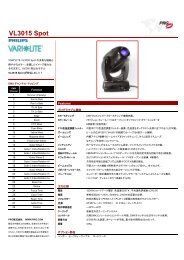
Figure 1: Series 400 Disconnect Front Panel<br />
4 02.9680.0200 A<br />
GROUND<br />
400A MAX<br />
YØ AMPS<br />
YØ<br />
NEUTRAL<br />
120/208V<br />
3ØY/30 A<br />
ZØ AMPS<br />
ZØ<br />
OUTPUT<br />
VOLTAGES<br />
TEST POINT<br />
FUSES<br />
1A / 250V<br />
AGC1<br />
Voltmeters - measures phase voltages<br />
to ensure supply voltage is correct.<br />
Voltage input to the Cam-Loks is<br />
measured before the breakers and will<br />
show the input voltage even when the<br />
Main Breaker is off.<br />
Voltmeter Rocker Switch - allows<br />
connection of the meters between the<br />
three phases (Ø-Ø) or between each<br />
phase and neutral (Ø-N).<br />
Current Meters - measures current<br />
flowing in each phase and neutral<br />
circuit.<br />
Test Points - to meter the output<br />
voltages after the Main Breaker.<br />
Pilot Light - indicates when Main<br />
Breaker is ON. Provides a Push-To-Test<br />
function.<br />
Main Breaker - provides system<br />
protection.<br />
Convenience Outlet (2) - Edison style<br />
receptacle, which provides power for<br />
optional work lights, test equipment, etc.<br />
Neutrik® Power Outlet (2) -<br />
provides power for control consoles and<br />
support equipment.<br />
L6-20 Power Outlet - provides 208V<br />
power for a single luminaire.<br />
Inrush Limit Setting - adjustment<br />
allows Inrush Limit to be set between<br />
2000 and 4000 Amps.<br />
L21-30R Power Outlet (2) - provides<br />
120/208V 30 Amp, 3-phase power.
S-400<br />
400 AMP<br />
DISCONNECT<br />
INPUT CONNECTIONS<br />
MUST BE MADE<br />
IN THE FOLLOWING<br />
ORDER:<br />
1) CONNECT GROUND<br />
2) CONNECT NEUTRAL<br />
3) CONNECT PHASES<br />
DISCONNECT IN<br />
REVERSE ORDER<br />
GND<br />
GND<br />
GND<br />
120/208V 3Ø OUTPUTS 400A PER Ø MAX<br />
NEUT<br />
NEUT<br />
NEUT XØ<br />
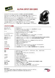
Figure 2: Series 400 Disconnect Rear Panel<br />
OVERVIEW : CONTROLS AND INDICATORS<br />
02.9680.0200 A 5<br />
YØ<br />
YØ<br />
120/208V 3Ø INPUTS 400A PER Ø MAX<br />
XØ YØ<br />
NEUT<br />
NEUT<br />
NEUT<br />
XØ<br />
XØ<br />
YØ<br />
ZØ<br />
ZØ<br />
ZØ<br />
ZØ<br />
Power Output Connectors -<br />
Two sets of six Cam-Lok<br />
connectors for power output<br />
to power distribution systems.<br />
Neon Phase Lamps -<br />
Indicate presence of AC<br />
voltage for each of three<br />
phases.<br />
Power Input Connectors -<br />
Six 400 Amp Cam-Lok<br />
connectors for house power<br />
feed.
<strong>PRG</strong> SERIES 400 400 AMP DISCONNECT USER MANUAL<br />
Proper Use and Operation<br />
Please observe the following safety, use and operational guidelines:<br />
• The Disconnect is intended for dry locations only and must be protected from rain and other<br />
moisture if used outdoors.<br />
• Two Disconnect racks may be stacked on top of each other. The upper rack’s casters will nest on<br />
top of the lower rack. When stacking racks, use a strap to tie them together for stability.<br />
• The Disconnect may be operated with the front cover in place for security or weather protection.<br />
The fans draw and exhaust to the rear of the rack.<br />
• The cooling fans turn on automatically when the internal bus bar temperatures exceed 135°F. This<br />
only happens when the rack is in the sun on a hot day or when it is loaded to its maximum. The fan<br />
may cycle on and off during normal operation.<br />
6 02.9680.0200 A
Installation<br />
Installing Series 400 Disconnect<br />
INSTALLATION : INSTALLING SERIES 400 DISCONNECT<br />
The Series 400 Disconnect is installed between the house service and a portable power distribution<br />
system, such as the Series 400 Power and Data Distribution System. It may also be used to protect a<br />
dimmer installation.<br />
CAUTION: Before installing, refer to "Proper Use and Operation" on page 6.<br />
WARNING: Ensure house service main breaker and Series 400 Disconnect breaker are OFF before<br />
connecting mains power cables. Ground should always be connected first.<br />
To install:<br />
Step 1. At house service main breaker, turn power OFF.<br />
Step 2. Meter voltage at the input of the house disconnect to ensure that all voltages are correct.<br />
Phase-to-phase voltages should be 208 Volts +/- 8 Volts. The voltage between Neutral and<br />
Ground should be less than 5 Volts.<br />
CAUTION: If the house breaker has a capacity greater than 400 Amps per phase, the pigtails<br />
connecting the S400 Disconnect cannot be longer than 10 feet.<br />
Step 3. Connect Cam-Lok 5-wire pigtails to house breaker output terminals. Ensure connections are<br />
tight to avoid heating of the connections.<br />
Step 4. Place Disconnect in desired location and remove front and back covers (Figure 3).<br />
NOTE: Two racks may be stacked on top of<br />
each other. The upper rack’s casters will nest<br />
on top of the lower rack. When stacking racks,<br />
use a strap to tie them together for stability.<br />
Figure 3: Removing Disconnect Rack Covers<br />
02.9680.0200 A 7
<strong>PRG</strong> SERIES 400 400 AMP DISCONNECT USER MANUAL<br />
Step 5. Ensure that Main Breaker is switched OFF (Figure 4).<br />
Step 6. At INPUTS, connect input power cable Cam-Loks in the following order:<br />
1) Ground, 2) Neutral 3) X Phase, 4) Y Phase, and 5) Z Phase.<br />
Pilot<br />
Light<br />
Main<br />
Breaker<br />
MAIN<br />
BREAKER<br />
ON<br />
PUSH<br />
TO<br />
TEST<br />
SWITCH TO OFF<br />
POSITION TO<br />
RESET BREAKER<br />
INPUT VOLTAGES<br />
XØ VOLTS YØ VOLTS ZØ VOLTS<br />
400 AMP<br />
MAIN BREAKER<br />
ON<br />
OFF<br />
2000A 3000A 4000A<br />
INRUSH LIMIT<br />
SETTING<br />
ARC MIXED TUNGSTEN<br />
LOADS LOADS LOADS<br />
Type 1 Enclosure<br />
For use in Dry Locations<br />
50 C Max Ambient<br />
For Use in Areas Not Readily Accessible by the General Public<br />
FOR USE BY QUALIFIED PERSONNEL ONLY<br />
WARNING - Risk of Electric Shock.<br />
Conforms to:<br />
Production Resource Group<br />
UL STD 1640<br />
8617 Ambassador Row<br />
Suite 120<br />
Certified to:<br />
Dallas, TX 75247<br />
CAN/CSA STD C22.2<br />
Made in USA<br />
No. 29<br />
XXXXX<br />
S-400<br />
400 AMP DISCONNECT<br />
MODEL 23-9680-0200<br />
Ø -Ø<br />
Ø -N<br />
600A MAX<br />
NEUT AMPS<br />
120/208V<br />
3ØY/30 A<br />
FRONT VIEW<br />
XØ AMPS<br />
XØ<br />
GROUND<br />
FOR BRANCH CIRCUIT USE ONLY<br />
120V / 15A 208V / 15A 208V / 20A<br />
120/208V<br />
3ØY/30 A<br />
400A MAX<br />
YØ AMPS<br />
YØ<br />
NEUTRAL<br />
120/208V<br />
3ØY/30 A<br />
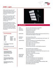
Figure 4: Turning Off Main Breaker and Connecting Cam-Loks<br />
Step 7. At OUTPUTS, connect output power cable Cam-Loks from power distribution equipment in<br />
the following order: 1) Ground, 2) Neutral 3) X Phase, 4) Y Phase, and 5) Z Phase.<br />
Note: Two complete sets of OUTPUT Cam-Lok connectors are provided in order to connect two<br />
separate power distribution systems.<br />
Note: A double set of Neutral connections are provided in the INPUT and OUTPUT Cam-Lok sets for<br />
use with low power factor loads, such as dimmers. Since low power factor loads cause large neutral<br />
currents, the Disconnect is designed to handle up to 600 Amps of Neutral current if the input and<br />
Output cable sets have two Neutral conductors each. The double set of Neutral cables must be 4/0.<br />
8 02.9680.0200 A<br />
ZØ AMPS<br />
ZØ<br />
OUTPUT<br />
VOLTAGES<br />
TEST POINT<br />
FUSES<br />
1A / 250V<br />
AGC1<br />
CONNECTION<br />
ORDER:<br />
1) Ground<br />
2) Neutral<br />
3) X Phase<br />
4) Y Phase<br />
5) Z Phase<br />
Cam-Lok Input<br />
Connectors<br />
WARNING: RISK OF ELECTRICAL SHOCK!<br />
Ensure house service main breaker and Disconnect<br />
breaker are OFF before connecting mains power<br />
cables. Ground should always be connected first.<br />
Cam-Lok Output Connectors (Two Sets)<br />
S-400<br />
400 AMP<br />
DISCONNECT<br />
INPUT CONNECTIONS<br />
MUST BE MADE<br />
IN THE FOLLOWING<br />
ORDER:<br />
1) CONNECT GROUND<br />
2) CONNECT NEUTRAL<br />
3) CONNECT PHASES<br />
DISCONNECT IN<br />
REVERSE ORDER<br />
GND<br />
GND<br />
GND<br />
120/208V 3Ø OUTPUTS 400A PER Ø MAX<br />
NEUT<br />
NEUT<br />
NEUT XØ<br />
REAR VIEW<br />
YØ<br />
YØ<br />
120/208V 3Ø INPUTS 400A PER Ø MAX<br />
XØ YØ<br />
NEUT<br />
NEUT<br />
NEUT<br />
XØ<br />
XØ<br />
YØ<br />
ZØ<br />
ZØ<br />
ZØ<br />
ZØ
INSTALLATION : INSTALLING SERIES 400 DISCONNECT<br />
Set the Inrush Current Limit:<br />
Some loads, such as incandescent lamps or electric motors, can draw a large surge of current through<br />
the Main Breaker when they are quickly energized with voltage. When the Inrush Current Limit of the<br />
Main Breaker is exceeded, the Breaker will trip within a half cycle of the AC line. It is important that<br />
the Inrush Current Limit be properly adjusted so that these normal, but large surges do not cause<br />
nuisance tripping of the Main Breaker.<br />
CAUTION: 1) If the Inrush Current Limit is set too high, the Main Breaker may not respond quickly<br />
enough to a hard fault in the output cables feeding the load resulting in excessive damage to the cables.<br />
2) DO NOT adjust the Inrush Setting while the unit is under load.<br />
Recommended Settings...<br />
• For loads consisting mainly of arc lamp power supplies, set the Inrush Limit to its minimum of<br />
2000 Amps.<br />
• For loads consisting mainly of high wattage incandescent lamps, set the Inrush Limit to 4000<br />
Amps.<br />
• For mixed loads, try an intermediate setting near 3000 Amps.<br />
Note: It is important to note that this setting applies to INRUSH and not OVERALL amperage. For<br />
example, setting the inrush to 2000 amps does not mean that the switch will now trip at a normal load<br />
of 200 amps-per-leg instead of 400 amps-per-leg.<br />
Once the load system is installed, connected and ready to test, "bump" the entire cold load to make<br />
sure the Main Breaker does not trip. If it trips, increase the Inrush setting moderately, then wait 5<br />
minutes for the lamps to cool and "bump the system again.<br />
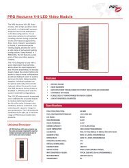
Step 1. Set Inrush Current Limit considering the type of load that the Disconnect will be protecting<br />
(refer to guidelines above). The Inrush Current Limit adjustment is located directly below<br />
the Main Breaker handle (Figure 5) and is adjusted by inserting a flat blade screwdriver into<br />
the vertical slot of the curved, recessed control. Moving the control to the left reduces the<br />
Main Breaker's tolerance of inrush current and moving it to the right increases the Main<br />
Breaker's tolerance.<br />
XØ VOLTS<br />
MAIN<br />
BREAKER<br />
ON<br />
PUSH<br />
TO<br />
TEST<br />
MAIN CIRCUIT BREAKER IS SUITABLE<br />
FOR CONTINUOUS OPERATION AT<br />
400 AMPERES.<br />
DISJONCTEUR DU CIRCUIT PRINCIPAL<br />
A MOINS QU'IL NE CONVIENNE POUR<br />
SERVICE CONTINU A 400 AMPERES.<br />
SWITCH TO OFF<br />
POSITION TO<br />
RESET BREAKER<br />
INPUT VOLTAGES<br />
YØ VOLTS ZØ VOLTS<br />
400 AMP<br />
MAIN BREAKER<br />
ON<br />
INRUSH LIMIT<br />
SETTING<br />
ARC MIXED TUNGSTEN<br />
LOADS LOADS LOADS<br />
S-400<br />
400 AMP DISCONNECT<br />
MODEL 23-9680-0200<br />
OFF<br />
2000A 3000A 4000A<br />
Ø -Ø<br />
Ø -N<br />
600A MAX<br />
NEUT AMPS<br />
120V / 15A 208V / 15A 208V / 20A<br />
120/208V<br />
Y/30 A<br />
X Ø AMPS<br />
XØ<br />
GROUND<br />
FOR BRANCH CIRCUIT USE ONLY<br />
120/208V<br />
3ØY/30 A<br />
400A MAX<br />
YØ AMPS<br />
YØ<br />
NEUTRAL<br />
ZØ<br />
120/208V<br />
3ØY/30 A<br />
ZØ AMPS<br />
OUTPUT<br />
VOLTAGES<br />
TEST POINT<br />
FUSES<br />
1A / 250V<br />
AGC1<br />
INRUSH LIMIT<br />
SETTING<br />
2000A 3000A<br />
ARC<br />
LOADS<br />
Figure 5: Inrush Limit Setting Switch<br />
02.9680.0200 A 9<br />
4000A<br />
MIXED TUNGSTEN<br />
LOADS LOADS
<strong>PRG</strong> SERIES 400 400 AMP DISCONNECT USER MANUAL<br />
Power Up Sequence<br />
Use the following procedure to power up unit:<br />
Step 1. At house service main breaker, turn power ON.<br />
Step 2. At rear of Disconnect, verify all phase indicators are lit (Figure 6).<br />
DISCONNECT<br />
INPUT CONNECTIONS<br />
MUST BE MADE<br />
IN THE FOLLOWING<br />
ORDER:<br />
1) CONNECT GROUND<br />
2) CONNECT NEUTRAL<br />
3) CONNECT PHASES<br />
DISCONNECT IN<br />
REVERSE ORDER<br />
GND<br />
NEUT XØ<br />
120/208V 3Ø INPUTS 400A PER Ø MAX<br />
NEUT<br />
NEUT<br />
XØ YØ<br />
XØ<br />
Figure 6: Phase Indicators Location<br />
Step 3. At front of Disconnect, check AC voltmeters. Voltages should read as follows:<br />
Voltmeter Connection Voltage<br />
Neutral to X 120V ± 5V<br />
Neutral to Y 120V ± 5V<br />
Neutral to Z 120V ± 5V<br />
X to Y 208V ± 8V<br />
Y to Z 208V ± 8V<br />
Z to X 208V ± 8V<br />
Step 4. If meter readings are nominal, switch Main Breaker to the ON position (Figure 4).<br />
Step 5. Verify that test point readings match LED meter readings for proper voltage. Note: Since the<br />
test points are after the Main Breaker, their voltages may be slightly lower than those<br />
indicated by the digital meters when the Disconnect is under load. This is due to the internal<br />
resistance of the breaker causing a slight voltage drop when current flows through it.<br />
Note: The Pilot Light indicates when Main Breaker is energized (Figure 4). Press to test LED before<br />
Main Breaker is "ON."<br />
10 02.9680.0200 A<br />
YØ<br />
ZØ<br />
ZØ<br />
ZØ<br />
Phase Indicators
Maintenance<br />
Cleaning/Replacing Rack Air Filters<br />
MAINTENANCE : CLEANING/REPLACING RACK AIR FILTERS<br />
The air filters, located in the interior rack assembly, will require periodic cleaning. The frequency will<br />
depend on the amount of use and/or exposure to dusty environments.<br />
Parts:<br />
40.7155.0120.0 FILTER, FAN 120MM, MESH ALUMINUM<br />
Tools:<br />
#2 slotted screwdriver<br />
WARNING: Remove power from rack before performing any maintenance procedures.<br />
To clean/replace rack air filters:<br />
Step 1. Disconnect power to rack.<br />
Step 2. Remove rack assembly from rolling rack case by removing ten 10-32 x 1/2" PTB black zinc<br />
screws.<br />
Step 3. Using screwdriver, free filter from enclosure.<br />
Step 4. Clean filter with soap and water. Dry thoroughly.<br />
Step 5. Re-install filter.<br />
Step 6. Re-install rack assembly into rolling rack case.<br />
10-32 x 1/2" PTB<br />
Black Zinc Screw (10)<br />
Rack Assembly<br />
Rolling Rack Case<br />
Rack Assembly<br />
Figure 7: Removing Rack Air Filters<br />
Fan Filter<br />
02.9680.0200 A 11
<strong>PRG</strong> SERIES 400 400 AMP DISCONNECT USER MANUAL<br />
Specifications<br />
Technical Specifications<br />
RATINGS and AMPACITY<br />
Voltage Rating: 120/208V 3-phase wye with Neutral and Ground<br />
Line Frequency: 50 - 60 Hz<br />
Current Rating, Phases: 400 Amps per phase continuous<br />
Current Rating, Neutral: 600 Amps continuous<br />
Current Rating, Ground: 400 Amps<br />
Fault Current Interrupting Capacity: 42,000 Amps<br />
Fault Current Interrupt Time: Circuit clears in less than one line cycle<br />
MAIN BREAKER<br />
Type: Thermal-Magnetic, Square D Model LAL36400<br />
Number of Poles: 3<br />
Voltage Rating: 600V AC<br />
Current Rating: 400 Amps<br />
Inrush Overload Limit: Adjustable from 2000A to 4000A<br />
DIGITAL LED METERS (7)<br />
Update Rate: 2.5 samples/sec.<br />
Display: 3-digit reading<br />
INPUT VOLTMETERS (3)<br />
Accuracy: ± 1 Volt<br />
Input Range: 85 - 264 Volts AC<br />
Overload Protection: 300V AC<br />
OUTPUT AMMETERS (4)<br />
Phase Current Meters full scale reading: 400 Amps<br />
Neutral Current Meter full scale reading: 600 Amps<br />
Overcurrent Rating: 1.5X rated full scale reading<br />
Accuracy (sine wave): ±0.15% of full scale or ±6 counts<br />
ENVIRONMENTAL<br />
Operational Temperature Range: -20° C to +50° C<br />
Cooling: Two thermostatically controlled fans<br />
For Dry Locations Only<br />
12 02.9680.0200 A
DIMENSIONS and WEIGHT<br />
Unit in Rolling Rack: 22.5"(L) x 22.5"(W) x 30.5"(H)<br />
Stand-Alone Panel Without Rack: 8.5"(D) x 19"(W) x 23.5"(H)<br />
Weight: 153 lbs. with Rack / 79 lbs. without Rack<br />
COMPLIANCE<br />
UL Standard 1640<br />
Canadian Standard CAN/CSA STD C22.2 No.29<br />
Intertek ETL Safety Mark<br />
SPECIFICATIONS : TECHNICAL SPECIFICATIONS<br />
02.9680.0200 A 13
<strong>PRG</strong> SERIES 400 400 AMP DISCONNECT USER MANUAL<br />
Notes<br />
14 02.9680.0200 A