
You also want an ePaper? Increase the reach of your titles
YUMPU automatically turns print PDFs into web optimized ePapers that Google loves.
Step 4<br />
Decide how you want your FX Loop to function<br />
with respect to input/output level control using<br />
trim or chassis mount pots or a basic install by<br />
jumping the trim S and trim R pads.<br />
or increase the 470k Ohm resistors before and<br />
after the return gain.<br />
For a basic install, solder a wire jumper from<br />
one of the trim S pads to the other. Do the<br />
same for the trim R pads. This will complete the<br />
FX Loop circuit.<br />
For input/output level control, solder the wiper<br />
of a 1M Ohm audio taper trimpot or an<br />
equivalent panel mount potentiometer to the<br />
trim S pad furthest away from the switch, and<br />
solder any of the outside pins of the<br />
potentiometer to the other trim S pad. Solder<br />
the final pin of the potentiometer to ground.<br />
This will complete the FX Loop circuit. Do the<br />
same for trim R.<br />
Resistors can also be soldered into the trim S<br />
and trim R pads if a fixed control of the send or<br />
return is desired.<br />
With stock components, installing the FX Loop<br />
in active mode will reduce your signal 10dB<br />
after the buffer stage of the circuit. On return,<br />
the signal will go through a gain stage that<br />
brings it back up 16dB. Therefore, the FX Loop<br />
will deliver a signal that is 6dB hotter. This can<br />
be trimmed by using the trim R output control,<br />
with the output potentiometer on your effects<br />
rack if you have one, or with your master<br />
volume. A signal flow is shown below. The FX<br />
Loop board can be re-configured for other level<br />
considerations by adjusting the voltage dividers<br />
shown. To permanently adjust the send to a<br />
higher level, simply increase the 470 Ohm<br />
resistor after the send buffer. To permanently<br />
adjust the return gain up or down, just reduce<br />
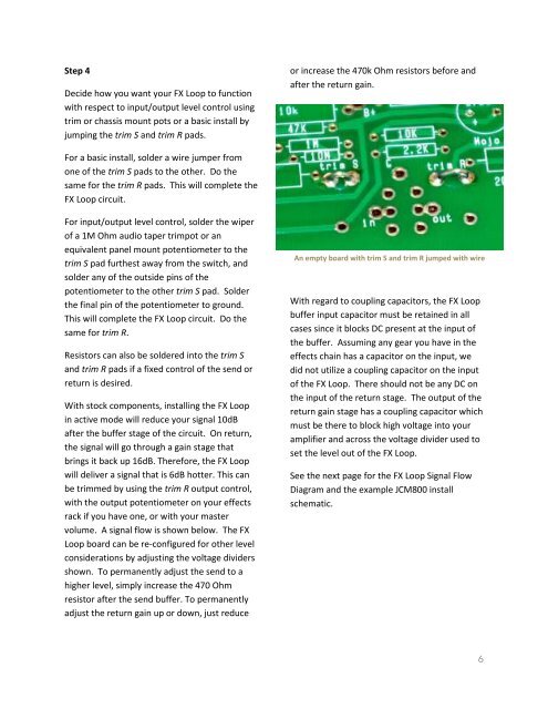
An empty board with trim S and trim R jumped with wire<br />
With regard to coupling capacitors, the FX Loop<br />
buffer input capacitor must be retained in all<br />
cases since it blocks DC present at the input of<br />
the buffer. Assuming any gear you have in the<br />
effects chain has a capacitor on the input, we<br />
did not utilize a coupling capacitor on the input<br />
of the FX Loop. There should not be any DC on<br />
the input of the return stage. The output of the<br />
return gain stage has a coupling capacitor which<br />
must be there to block high voltage into your<br />
amplifier and across the voltage divider used to<br />
set the level out of the FX Loop.<br />
See the next page for the FX Loop Signal Flow<br />
Diagram and the example JCM800 install<br />
schematic.<br />
6