
You also want an ePaper? Increase the reach of your titles
YUMPU automatically turns print PDFs into web optimized ePapers that Google loves.
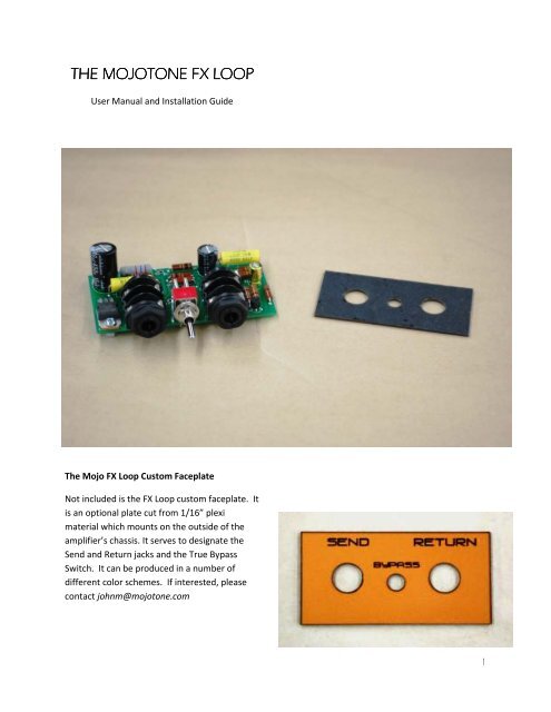
THE MOJOTONE FX LOOP<br />
User Manual and Installation Guide<br />
The Mojo FX Loop Custom Faceplate<br />
Not included is the FX Loop custom faceplate. It<br />
is an optional plate cut from 1/16” plexi<br />
material which mounts on the outside of the<br />
amplifier’s chassis. It serves to designate the<br />
Send and Return jacks and the True Bypass<br />
Switch. It can be produced in a number of<br />
different color schemes. If interested, please<br />
contact johnm@mojotone.com<br />
1
How to Install the Mojo Fx Loop to Your<br />
Amplifier’s Chassis<br />
Note: The following steps should be performed<br />
with the amplifier’s power cable unplugged.<br />
Follow all electrical safety guidelines including<br />
discharging the amplifier’s capacitors. If you<br />
do not feel confident to perform the following<br />
installation steps, let a qualified technician<br />
complete the work.<br />
Step 1<br />
Start by placing the template or faceplate on<br />
the amplifier chassis where the FX Loop will<br />
mount. Ideally, since the signal will be sent<br />
through it, the FX Loop should be placed as far<br />
away from the output as possible. As a test,<br />
place the FX Loop in the location where it will<br />
be installed, and make sure it does not interfere<br />
with any other part of the amplifier.<br />
Trace the insides of the holes on the template<br />
or faceplate onto the amplifier’s chassis using a<br />
marker, pen, or pencil.<br />
Step 2<br />
Drill the holes with either a step bit or a regular<br />
metal cutting bit. Holes for the Send and<br />
Return should be 7/16” in diameter. The hole<br />
for the Bypass should be 3/16“ in diameter.<br />
Step 3<br />
Depending on the thickness of the amplifier<br />
chassis and use of the FX Loop faceplate, you<br />
may not be able to use these parts to mount<br />
the FX Loop. In any case, they are not<br />
necessary for installation.<br />
2
Insure that the FX Loop fits into the holes and<br />
sits flush against the amplifier chassis. Again,<br />
make sure the FX Loop’s components are clear<br />
of obstruction from any other part of the<br />
amplifier.<br />
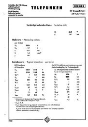
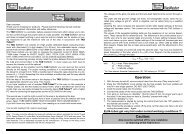
Use the supplied nuts to secure the FX Loop to<br />
the amplifier chassis. Here is an example of<br />
mounting the FX Loop without the optional<br />
faceplate. In this case, there is enough room to<br />
use the nut for the Bypass switch.<br />
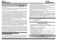
Here is an example utilizing the optional<br />
faceplate. Note that mounting the FX Loop<br />
component side up will position the Send jack<br />
on the left and the Return jack on the right. The<br />
opposite will result if the FX Loop is mounted<br />
component side down.<br />
3
Wiring the Mojo FX Loop into Your Amplifier<br />
Step 1<br />
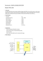
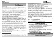
Locate on the FX Loop component board the<br />
pads for the:<br />
• Power Supply (B+)<br />
• Ground (G)<br />
• Signal In (in)<br />
• Signal Out (out)<br />
• Send Trimpot (trim S)<br />
• Return Trimpot (trim R)<br />
Notice that there are two pads each for the<br />
Send and Return trimpots. These will be used<br />
to wire a trimpot, panel mount pot, resistor, or<br />
a wire jumper in line with the signal path.<br />
B+ and Ground Terminals<br />
In and Out Terminals<br />
Trim S and Trim R Terminals<br />
4
Step 2<br />
Solder a jumper wire from the low-power side<br />
of the amplifier’s power supply line, which is<br />
usually after the final filtering capacitor and<br />
drop resistor, to the B+ pad on the FX Loop<br />
component board. This voltage should not be<br />
under 150V or over 350V.<br />
Solder a wire from the Ground (G) pad on the<br />
FX Loop component board to a ground that<br />
produces the least amount of hum noise. This<br />
will usually be the cathode ground for the stage<br />
before or after the insertion location of the FX<br />
Loop.<br />
Choose a point in the signal path to break and<br />
insert the FX Loop. The circuit is optimized for a<br />
point just before the driver or phase inverter<br />
stage. In our JCM800 test circuit, the FX Loop<br />
either goes between the treble and the master<br />
potentiometers, or just before the coupling<br />
capacitor into the driver or phase inverter stage<br />
(see the schematic on Page 7).<br />
Solder wires to the Signal In (in) and Signal Out<br />
(out) pads on the FX Loop board, and run them<br />
to the area of the preamp where signal path will<br />
be broken. If this is on a PCB of which you do<br />
not want to cut traces, pull the coupling<br />
capacitor from the board, and use the<br />
remaining holes for the installation.<br />
Remember, however, to place the capacitor in<br />
line with the return lead of the FX Loop.<br />
If there are no DC considerations where you are<br />
adding the FX Loop in the board, then it can be<br />
added without capacitors. If you experience<br />
any sort of failure on install with the board, it is<br />
likely there was a bias consideration that is<br />
being changed by the installation, and the<br />
circuit will need to be isolated with capacitors.<br />
5
Step 4<br />
Decide how you want your FX Loop to function<br />
with respect to input/output level control using<br />
trim or chassis mount pots or a basic install by<br />
jumping the trim S and trim R pads.<br />
or increase the 470k Ohm resistors before and<br />
after the return gain.<br />
For a basic install, solder a wire jumper from<br />
one of the trim S pads to the other. Do the<br />
same for the trim R pads. This will complete the<br />
FX Loop circuit.<br />
For input/output level control, solder the wiper<br />
of a 1M Ohm audio taper trimpot or an<br />
equivalent panel mount potentiometer to the<br />
trim S pad furthest away from the switch, and<br />
solder any of the outside pins of the<br />
potentiometer to the other trim S pad. Solder<br />
the final pin of the potentiometer to ground.<br />
This will complete the FX Loop circuit. Do the<br />
same for trim R.<br />
Resistors can also be soldered into the trim S<br />
and trim R pads if a fixed control of the send or<br />
return is desired.<br />
With stock components, installing the FX Loop<br />
in active mode will reduce your signal 10dB<br />
after the buffer stage of the circuit. On return,<br />
the signal will go through a gain stage that<br />
brings it back up 16dB. Therefore, the FX Loop<br />
will deliver a signal that is 6dB hotter. This can<br />
be trimmed by using the trim R output control,<br />
with the output potentiometer on your effects<br />
rack if you have one, or with your master<br />
volume. A signal flow is shown below. The FX<br />
Loop board can be re-configured for other level<br />
considerations by adjusting the voltage dividers<br />
shown. To permanently adjust the send to a<br />
higher level, simply increase the 470 Ohm<br />
resistor after the send buffer. To permanently<br />
adjust the return gain up or down, just reduce<br />
An empty board with trim S and trim R jumped with wire<br />
With regard to coupling capacitors, the FX Loop<br />
buffer input capacitor must be retained in all<br />
cases since it blocks DC present at the input of<br />
the buffer. Assuming any gear you have in the<br />
effects chain has a capacitor on the input, we<br />
did not utilize a coupling capacitor on the input<br />
of the FX Loop. There should not be any DC on<br />
the input of the return stage. The output of the<br />
return gain stage has a coupling capacitor which<br />
must be there to block high voltage into your<br />
amplifier and across the voltage divider used to<br />
set the level out of the FX Loop.<br />
See the next page for the FX Loop Signal Flow<br />
Diagram and the example JCM800 install<br />
schematic.<br />
6
Signal Flow Diagram of the Mojo FX Loop<br />
Schematic of the Example Install using the JCM800<br />
7
Schematic of an Example Install in a JTM-45 without a Master Volume<br />
Dimensions in Inches<br />
8
Template Dimensions in Inches<br />
9