Switch mode power supply DC 1000 CAN
Switch mode power supply DC 1000 CAN
Switch mode power supply DC 1000 CAN
You also want an ePaper? Increase the reach of your titles
YUMPU automatically turns print PDFs into web optimized ePapers that Google loves.
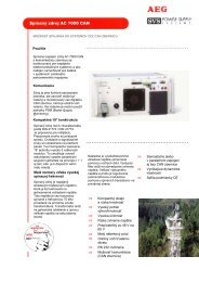
<strong>Switch</strong> <strong>mode</strong> <strong>power</strong> <strong>supply</strong><br />
<strong>DC</strong> <strong>1000</strong> <strong>CAN</strong><br />
FOR A MULTITUDE<br />
OF INDUSTRIAL APPLICATIONS<br />
Applications<br />
The switch <strong>mode</strong> <strong>power</strong> <strong>supply</strong> <strong>DC</strong> <strong>1000</strong><br />
<strong>CAN</strong> with communications capability<br />
from AEG SVS is manufactured for the<br />
connection voltages 220 V <strong>DC</strong> and<br />
110 V <strong>DC</strong>. It is designed for a wide<br />
variety of applications such as <strong>supply</strong>ing<br />
<strong>power</strong> to the control room in<br />
conventional <strong>power</strong> stations and in<br />
nuclear <strong>power</strong> stations, as well as<br />
<strong>supply</strong>ing <strong>power</strong> on board rail vehicles<br />
and ships. It is used to <strong>power</strong> the <strong>DC</strong><br />
loads from a secured 220 V (110 V) <strong>DC</strong><br />
busbar with high operating reliability. The<br />
<strong>DC</strong> <strong>1000</strong> makes it possible to set up<br />
redundant <strong>power</strong> <strong>supply</strong> units, either with<br />
or without batteries connected in parallel<br />
in the device output. The <strong>DC</strong> <strong>1000</strong> is<br />
used to <strong>supply</strong> <strong>power</strong> to all kinds of <strong>DC</strong><br />
loads and implement constant voltage<br />
and current sources.<br />
............................................<br />
...<br />
............................................<br />
Communication<br />
This device is fully functional in individual<br />
operation and can furthermore be<br />
controlled and monitored via the<br />
interference-free, digital <strong>CAN</strong> BUS. The<br />
additionally available control and<br />
monitoring unit PSC 100 makes it<br />
possible to implement complex <strong>DC</strong><br />
systems with very little effort. Therefore,<br />
in addition to the cabling of the <strong>power</strong><br />
section, only a simple and clear bus<br />
wiring between the <strong>DC</strong> <strong>1000</strong> and the<br />
PSC 100 components is necessary.<br />
Ease of operation<br />
The connections are provided on the<br />
front of the unit for easy access.<br />
Compact design<br />
The compact design as a<br />
19“ panel mounting unit with only two<br />
height units allows redundant systems to<br />
be constructed even in very small<br />
spaces through parallel connection<br />
according to the n+1 principle.<br />
⇐ Input voltage range<br />
-23 % to +30 % Uin<br />
⇐ Future-oriented<br />
microprocessor technology<br />
⇐ Capable of communication<br />
(<strong>CAN</strong> BUS)<br />
⇐ When operated with PSC 100:<br />
- active current sharing<br />
- 4 charge characteristics,<br />
1 of which is temperaturecontrolled<br />
⇐ Low start current<br />
through intelligent switch-on<br />
management, especially<br />
when devices are connected<br />
in parallel<br />
⇐ Permanently proof against<br />
short circuit<br />
⇐ CE-compliant<br />
⇐ ISO 9001 certified
<strong>Switch</strong> <strong>mode</strong> <strong>power</strong> <strong>supply</strong> <strong>DC</strong> <strong>1000</strong> <strong>CAN</strong><br />
Technical Data<br />
TYPE DESIGNATION G110 G 24/30<br />
Wrg-Cpü<br />
G220 G 24/30<br />
Wrg-Cpü<br />
G110 G 48/15<br />
Wrg-Cpü<br />
G220 G 48/15<br />
Wrg-Cpü<br />
G110 G 60/15<br />
Wrg-Cpü<br />
G220 G 60/15<br />
Wrg-Cpü<br />
Order-Number 3 000 000 754 3 000 000 755 3 000 000 756 3 000 000 757 3 000 000 812 3 000 000 813<br />
Rated connected voltage 110 V <strong>DC</strong> 220 V <strong>DC</strong> 110 V <strong>DC</strong> 220 V <strong>DC</strong> 110 V <strong>DC</strong> 220 V <strong>DC</strong><br />
Voltage tolerance -23% to +30%<br />
Inrush current<br />
≤ Nominal input current<br />
Current consumption 8.3 A <strong>DC</strong> 4 A <strong>DC</strong> 8.5 A <strong>DC</strong> 4.0 A <strong>DC</strong> 9.8 A <strong>DC</strong> 5.0 A <strong>DC</strong><br />
(approx. values)<br />
Required input fuse 12 A 6 A 12 A 6 A 15 A 10 A<br />
Efficiency 91% 92% 92% 93% 92% 93%<br />
Set output voltage 26.76 V <strong>DC</strong> ± 1 % 53.5 V <strong>DC</strong> ± 1 % 66.9 V <strong>DC</strong> ±1 %<br />
Setting range 20 ... 30 V 40 ... 60 V 50 ... 75 V<br />
Set output current 30 A <strong>DC</strong> ± 2% 15 A <strong>DC</strong> ± 2% 15 A <strong>DC</strong> ± 2%<br />
Setting range 1.5 ... 30 A <strong>DC</strong> 0.75 ... 15 A <strong>DC</strong> 0.75 ... 15 A <strong>DC</strong><br />
Short circuit response<br />
Permanently short circuit proof<br />
Voltage ripple < 50 mV pp < 50 mV pp < 2 mV acc. to CCITT<br />
Interference emission /<br />
In acc. to EN 6<strong>1000</strong>-6-3 / in acc. to EN 6<strong>1000</strong>-6-2<br />
Interference immunity<br />
Low voltage funktion with save disc. In acc. to EN 50178<br />
Characteristic line CVCC curve in acc. to DIN 41772 / DIN 41773<br />
Input-side<br />
Undervoltage / overvoltage with switch-off, self-acknowledging<br />
monitoring systems With 110 V input With 220 V input<br />
Undervoltage<br />
OFF<br />
ON<br />
≤ 80 V <strong>DC</strong><br />
> 85 V <strong>DC</strong><br />
≤ 159 V <strong>DC</strong><br />
> 169 V <strong>DC</strong><br />
Setting range OFF 80 V ... 110 V 159 V ... 220 V<br />
Overvoltage<br />
OFF<br />
ON<br />
> 148 V <strong>DC</strong><br />
≤ 143 V <strong>DC</strong><br />
> 296 V <strong>DC</strong><br />
≤ 286 V <strong>DC</strong><br />
Setting range OFF 110 V ... 148 V 220 V ... 296 V<br />
Output-side<br />
Output voltage / heat sink temperature with derating and switch-off<br />
Monitoring systems With 24 V output With 48 V output With 60 V output<br />
Undervoltage<br />
Only message<br />
OFF<br />
ON<br />
≤ 24 V <strong>DC</strong><br />
> 25 V <strong>DC</strong><br />
≤ 48 V <strong>DC</strong><br />
> 50 V <strong>DC</strong><br />
≤ 60 V <strong>DC</strong><br />
> 62.5 V <strong>DC</strong><br />
Setting range OFF 20 V ... 28 V 40 V ... 56 V 49 V ... 68 V<br />
Overvoltage<br />
with switch-off<br />
OFF<br />
ON<br />
> 28 V <strong>DC</strong><br />
≤ 27.2 V <strong>DC</strong><br />
> 56 V <strong>DC</strong><br />
≤ 54.4 V <strong>DC</strong><br />
> 70 V <strong>DC</strong><br />
≤ 68 V <strong>DC</strong><br />
Setting range OFF 25 V ... 36 V 50 V ... 72 V 62 V ... 90 V<br />
Messages and displays Load: Green LED; fault: Red LED; Uo>: Red LED; Uo


