2400A and 2400THA Direct Wire Photoelectronic Smoke Detectors
2400A and 2400THA Direct Wire Photoelectronic Smoke Detectors
2400A and 2400THA Direct Wire Photoelectronic Smoke Detectors

Create successful ePaper yourself
Turn your PDF publications into a flip-book with our unique Google optimized e-Paper software.
INSTALLATION AND MAINTENANCE INSTRUCTIONS<br />
<strong>2400A</strong> <strong>and</strong> <strong>2400THA</strong> <strong>Direct</strong> <strong>Wire</strong><br />
<strong>Photoelectronic</strong> <strong>Smoke</strong> <strong>Detectors</strong><br />
6581 Kitimat Rd., Unit #6, Mississauga, Ontario, L5N 3T5<br />
1-800-SENSOR2, FAX: 905-812-0771<br />
www.systemsensor.ca<br />
Specifications<br />
Diameter:<br />
Height:<br />
Weight:<br />
Operating Temperature Range:<br />
Operating Humidity Range:<br />
Maximum Air Velocity:<br />
Locking Alarm:<br />
Electrical Ratings<br />
System Voltage:<br />
Maximum Ripple Voltage:<br />
Start-up Capacitance:<br />
St<strong>and</strong>by Ratings:<br />
Alarm Ratings:<br />
Reset Voltage:<br />
Reset Time:<br />
Start-up Time:<br />
5.5 inches (140 mm)<br />
3.14 inches (80 mm)<br />
Add 0.5 inches (13 mm) for <strong>2400THA</strong><br />
0.7 lb. (310 gm)<br />
Model <strong>2400A</strong> — 0° to +49°C (32° to 120°F)<br />
Model <strong>2400THA</strong> — 0° to 38°C (32° to 100°F)<br />
10% to 93% Relative Humidity Non-condensing<br />
3000 ft/min (15m/s)<br />
Reset by momentary power interruption<br />
2/24 VDC<br />
4 Volts peak-to-peak<br />
0.02 µF Maximum<br />
8.5 VDC Minimum; 35 VDC Maximum<br />
20 µA Maximum<br />
4.2 VDC Minimum at 10 mA<br />
6.6 VDC Maximum at 100 mA<br />
Alarm current must be limited to 100mA maximum by the control panel. If<br />
used, the RA400ZA Remote Annunciator operates within the specified<br />
detector alarm currents.<br />
2.5 VDC Minimum<br />
0.3 S Maximum<br />
34 S Maximum<br />
Before Installing<br />
Please thoroughly read the System Sensor manual I56-<br />
407-XX, Guide for Proper Use of System <strong>Smoke</strong> <strong>Detectors</strong>.<br />
This manual provides detailed information on detector<br />
spacing, placement, zoning, wiring, <strong>and</strong> special applications.<br />
Copies of this manual are available at no charge<br />
from System Sensor. Please also refer to CAN4-S524,<br />
St<strong>and</strong>ard for the Installation of Fire Alarm Systems <strong>and</strong><br />
CEC Part 1, Sec. 32..<br />
NOTICE: This manual should be left with the owner/user<br />
of this equipment.<br />
IMPORTANT: This sensor must be tested <strong>and</strong> maintained<br />
regularly following CAN/ULC-S536 requirements. This<br />
sensor should be cleaned at least once a year.<br />
General Description<br />
System Sensor <strong>2400A</strong> photoelectronic detectors use stateof-the-art,<br />
optical sensing chambers. These detectors are<br />
designed to provide open area protection, <strong>and</strong> are intended<br />
for use with compatible ULC-listed 2-wire control panels<br />
only. The detector’s operation <strong>and</strong> sensitivity can be tested<br />
in place. Model <strong>2400THA</strong> has the same specifications as<br />
model <strong>2400A</strong>, but also features a restorable, built-in, fixed<br />
temperature (135°F) thermal detection unit.<br />
These detectors are latching type system detectors. When<br />
latched in alarm, the detectors must be reset by a momentary<br />
power interruption.<br />
An LED on the detector provides a local indication of the<br />
detector’s status. This LED blinks every 10 seconds when<br />
the detector is receiving power <strong>and</strong> ready in st<strong>and</strong>by <strong>and</strong><br />
is latched on continuously in alarm until the detector is<br />
reset. The detector provides an output for connection to<br />
an optional Remote Annunciator (Model RA400ZA). The<br />
Remote Annunciator mounts to a single gang box <strong>and</strong> provides<br />
a supplementary alarm indication.<br />
Spacing<br />
CAN/ULC-S524 defines the spacing requirements for<br />
smoke detectors, typically 30 feet when detectors are<br />
installed on a smooth ceiling. However, ALL installations<br />
must comply with CAN/ULC-S524 <strong>and</strong>/or special requirements<br />
of the authority having jurisdiction.<br />
D400-05-00 REV#-002 I56-1017-000
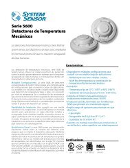
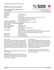
Figure 1. Flush mounting of <strong>2400THA</strong> smoke detector<br />
on 3 1 / 2<br />
-inch <strong>and</strong> 4-inch octagonal box:<br />
Figure 2. <strong>2400A</strong> <strong>Smoke</strong> detector mounting bracket:<br />
TAMPER<br />
RESISTANT<br />
TAB<br />
A78-1411-00<br />
Mounting<br />
Each <strong>2400A</strong> detector is supplied with a mounting bracket<br />
kit that permits the detector to be mounted:<br />
1. <strong>Direct</strong>ly to a 3 1 / 2<br />
-inch or 4-inch octagonal, 1 1 / 2<br />
-inch deep<br />
electrical box, (See Figure 1) or:<br />
2. To a 4-inch square electrical box by using the plaster<br />
ring with the supplied mounting bracket kit.<br />
Installation Wiring Guidelines<br />
All wiring must be installed in compliance with the Canadian<br />
Electrical Code <strong>and</strong> all applicable local codes,<br />
<strong>and</strong> any special requirements of the local authority having<br />
jurisdiction. Proper wire gauges should be used. The conductors<br />
used to connect smoke detectors to control panels<br />
<strong>and</strong> accessory devices should be color-coded to reduce<br />
the likelihood of wiring errors. Improper connections can<br />
prevent a system from responding properly in the event of<br />
a fire.<br />
For signal wiring (wiring between interconnected detectors),<br />
wire be no smaller than AWG 18 is recommended.<br />
However, the screws <strong>and</strong> clamping plate, in the base can,<br />
accommodate wire sizes up to AWG 12. The use of twisted<br />
pair wiring for the power (+ <strong>and</strong> -) loop is recommended to<br />
minimize the effects of electrical interference.<br />
TO MAKE DETECTOR TAMPER RESISTANT,<br />
BREAK OFF TAB EXTENSION<br />
AT SCRIBED LINE<br />
A78-534-00<br />
lation from the end of the wire <strong>and</strong> sliding the bare end<br />
of the wire under the clamping plate, <strong>and</strong> tightening the<br />
clamping plate screw. A wiring diagram for a typical 2-wire<br />
detector system is shown in Figure 3.<br />
NOTE: For system supervision — do not loop wire under<br />
terminals 1 <strong>and</strong> 2.<br />
NOTE: If remote annunciator is not used, polarity to detector<br />
may be reversed.<br />
Tamper-resistant Feature<br />
This detector includes a tamper-resistant feature that prevents<br />
removal of the detector without the use of a tool. To<br />
make the detector tamper-resistant, break off the smaller<br />
tab at the scribed line on the tamper resistant tab, on the<br />
detector mounting bracket (see Figure 2), then install the<br />
detector. To remove the detector from the bracket once it<br />
has been made tamper resistant, use a small screwdriver<br />
to depress the tamper-resistant tab located in the slot<br />
on the mounting bracket <strong>and</strong> turn the detector counterclockwise<br />
for removal.<br />
<strong>Smoke</strong> detectors <strong>and</strong> alarm system control panels have<br />
specifications for allowable loop resistance. Consult the<br />
control panel manufacturer’s specifications for the total<br />
loop resistance allowed for the control panel being used<br />
before wiring the detector loops.<br />
Make wire connections by stripping about 3 / 8<br />
inch of insu-<br />
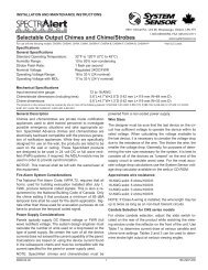
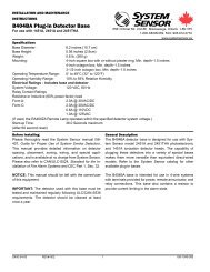
Figure 3. Wiring diagram for <strong>2400A</strong> smoke detector used with two-wire control panel:<br />
INITIATING<br />
LOOP<br />
+<br />
-<br />
+ -<br />
+<br />
-<br />
EOL<br />
RESISTOR<br />
LISTED<br />
COMPATIBLE<br />
CONTROL<br />
PANEL<br />
REMOTE<br />
ANNUNCIATOR<br />
+<br />
-<br />
3<br />
2 +<br />
1<br />
3<br />
REMOTE<br />
ANNUNCIATOR<br />
-<br />
2 1<br />
A78-1554-00<br />
OPTIONAL CLASS A WIRING<br />
NOTE: IF REMOTE ANNUNCIATOR IS NOT USED, POLARITY TO DETECTOR MAY BE REVERSED.<br />
D400-05-00 REV#-002 2 I56-1017-000
Installation<br />
Disable the power from initiating device circuits before installing<br />
detectors.<br />
1. <strong>Wire</strong> each detector following installation guidelines.<br />
2. Line up arrows on the detector with arrows on the<br />
mounting bracket.<br />
3. Turn the detector clockwise until it clicks into place.<br />
4. After all detectors have been installed, apply power to<br />
the control unit.<br />
5. Test the detector as described under TESTING.<br />
6. Reset the detector at the system control panel.<br />
7. Notify the proper authorities the system is in operation.<br />
Dust covers can be used to help limit dust entry to the detector.<br />
However, these covers are not a substitute for removing<br />
the detector during building construction. Remove<br />
any dust covers before placing the system in service.<br />
Testing<br />
Before testing, notify the proper authorities that the smoke<br />
detector system is undergoing maintenance, <strong>and</strong> the system<br />
will be temporarily out of service. Disable the zone<br />
or system undergoing maintenance to prevent unwanted<br />
alarms.<br />
Before testing the detector, look for the presence of the<br />
flashing LED. If it does not flash, power has been lost to<br />
the detector (check the wiring), or it is defective (return for<br />
repair – refer to Warranty information).<br />
<strong>Detectors</strong> must be tested after installation <strong>and</strong> following<br />
periodic maintenance. The <strong>2400A</strong>/<strong>2400THA</strong> may be tested<br />
as follows:<br />
A. Functional Tests<br />
Recessed Test Switch<br />
1. A test switch is located on the detector housing (See<br />
Figure 4).<br />
2. Press <strong>and</strong> hold the recessed test switch with a 0.1<br />
inch maximum diameter tool.<br />
3. The detector’s LED should light within 5 seconds.<br />
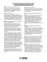
Figure 4. Top <strong>and</strong> side views showing position of test switch:<br />
B. Calibrated Test Card (R59-18-00)<br />
1. Remove the detector cover by placing a small bladed<br />
screwdriver in the side slot of the detector cover,<br />
twisting it slightly until the cover can be turned counterclockwise<br />
for removal.<br />
2. Insert the NO ALARM end of the test card fully into the<br />
test slot (See Figure 5) then slide it counterclockwise<br />
until it stops.<br />
3. The detector should not alarm after 20 seconds.<br />
4. Remove the test card by sliding it clockwise before<br />
removing, then insert the ALARM end.<br />
5. The LED should latch on within 20 seconds. An alarm<br />
should also be initiated at the panel.6. Put the cover<br />
back by gently rotating it clockwise until it locks in<br />
place.<br />
C. Test Module (System Sensor No. MOD400R/MOD400).<br />
The MOD400R or MOD400Test Module is used with an<br />
analog or digital voltmeter to check the detector sensitivity<br />
as described in the test module’s manual.<br />
D. Aerosol Generator (Gemini 501).<br />
Set the aerosol generator to represent 4%/Ft to 5%/Ft<br />
obscuration as described in the Gemini 501 manual.<br />
Using the bowl shaped applicator, apply aerosol until<br />
unit alarms.<br />
E. <strong>Direct</strong> Heat Test (<strong>2400THA</strong> only).<br />
To test the bi-metallic thermal collector on the <strong>2400THA</strong>,<br />
use a low powered heat gun or blow dryer, aiming the<br />
heat source across the detector. Hold the heat source<br />
about 12 inches (30 cm) from the detector to avoid damaging<br />
the plastic.When the heat rises to greater than<br />
135°F, the detector will latch in alarm. After the test, the<br />
bi-metallic collector will self-restore.<br />
Notify the proper authorities that the system is back on<br />
line. <strong>Detectors</strong> that fail these tests should be cleaned as<br />
described under MAINTENANCE <strong>and</strong> retested. If the detectors<br />
still fail these tests, they should be returned for repair.<br />
Notify the proper authorities the system is back on line.<br />
Maintenance<br />
NOTE: Before removing the detector, notify the proper authorities<br />
the smoke detector system is undergoing<br />
maintenance <strong>and</strong>, therefore, will be temporarily out<br />
of service. Disable the zone or system undergoing<br />
maintenance to prevent unwanted alarms.<br />
A78-1393-00<br />
D400-05-00 REV#-002 3 I56-1017-000
1. Remove the detector cover by placing a small bladed<br />
screwdriver in the side slot of the detector cover, twisting<br />
it slightly until the cover can be turned counterclockwise<br />
for removal.<br />
2. Vacuum the screen carefully without removing it. If further<br />
cleaning is required continue with step 3, otherwise<br />
skip to step 6.<br />
3. See Figure 5. Remove the screen by pulling it straight<br />
out. Vacuum the inside.<br />
4. Clean the vaned chamber piece by vacuuming or blowing<br />
out dust <strong>and</strong> particles.<br />
5. To replace the screen, orient it so that the arrow on top<br />
aligns with the test module socket of the detector. Carefully<br />
push the screen onto the base, making sure it fits<br />
tightly to the chamber.<br />
6. Replace the cover by gently rotating it clockwise until it<br />
locks in place.<br />
7. Notify the proper authorities the system is back on line.<br />
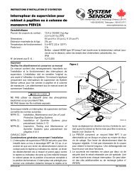
Figure 5. Removal of cover <strong>and</strong> screen for cleaning:<br />
TEST SLOT<br />
HEAD COVER<br />
REMOVAL SLOT<br />
REMOVABLE HEAD COVER<br />
CLEANABLE SCREEN<br />
P/N RS24 (W/O THERMAL)<br />
VANED CHAMBER<br />
A78-1213-01<br />
Please refer to insert for the Limitations of Fire Alarm Systems<br />
System Sensor warrants its enclosed smoke detector to be free from defects in materials<br />
<strong>and</strong> workmanship under normal use <strong>and</strong> service for a period of three years<br />
from date of manufacture. System Sensor makes no other express warranty for this<br />
smoke detector. No agent, representative, dealer, or employee of the Company has<br />
the authority to increase or alter the obligations or limitations of this Warranty. The<br />
Company’s obligation of this Warranty shall be limited to the repair or replacement<br />
of any part of the smoke detector which is found to be defective in materials or workmanship<br />
under normal use <strong>and</strong> service during the three year period commencing<br />
with the date of manufacture. After phoning System Sensor’s toll free number 1-<br />
800-SENSOR2 (736-7672) for a Return Authorization number, send defective units<br />
postage prepaid to: System Sensor, Repair Department,<br />
RA #__________, 6581 Kitimat Rd., Unit #6, Mississauga, Ontario, L5N 3T5.<br />
Three-Year Limited Warranty<br />
Please include a note describing the malfunction <strong>and</strong> suspected cause of failure.<br />
The Company shall not be obligated to repair or replace units which are found to<br />
be defective because of damage, unreasonable use, modifications, or alterations<br />
occurring after the date of manufacture. In no case shall the Company be liable for<br />
any consequential or incidental damages for breach of this or any other Warranty,<br />
expressed or implied whatsoever, even if the loss or damage is caused by the<br />
Company’s negligence or fault. Some states do not allow the exclusion or limitation<br />
of incidental or consequential damages, so the above limitation or exclusion may<br />
not apply to you. This Warranty gives you specific legal rights, <strong>and</strong> you may also<br />
have other rights under common law.<br />
D400-05-00 REV#-002 4 I56-1017-000<br />
© System Sensor Canada 2004