2400A and 2400THA Direct Wire Photoelectronic Smoke Detectors
2400A and 2400THA Direct Wire Photoelectronic Smoke Detectors
2400A and 2400THA Direct Wire Photoelectronic Smoke Detectors

Create successful ePaper yourself
Turn your PDF publications into a flip-book with our unique Google optimized e-Paper software.
Installation<br />
Disable the power from initiating device circuits before installing<br />
detectors.<br />
1. <strong>Wire</strong> each detector following installation guidelines.<br />
2. Line up arrows on the detector with arrows on the<br />
mounting bracket.<br />
3. Turn the detector clockwise until it clicks into place.<br />
4. After all detectors have been installed, apply power to<br />
the control unit.<br />
5. Test the detector as described under TESTING.<br />
6. Reset the detector at the system control panel.<br />
7. Notify the proper authorities the system is in operation.<br />
Dust covers can be used to help limit dust entry to the detector.<br />
However, these covers are not a substitute for removing<br />
the detector during building construction. Remove<br />
any dust covers before placing the system in service.<br />
Testing<br />
Before testing, notify the proper authorities that the smoke<br />
detector system is undergoing maintenance, <strong>and</strong> the system<br />
will be temporarily out of service. Disable the zone<br />
or system undergoing maintenance to prevent unwanted<br />
alarms.<br />
Before testing the detector, look for the presence of the<br />
flashing LED. If it does not flash, power has been lost to<br />
the detector (check the wiring), or it is defective (return for<br />
repair – refer to Warranty information).<br />
<strong>Detectors</strong> must be tested after installation <strong>and</strong> following<br />
periodic maintenance. The <strong>2400A</strong>/<strong>2400THA</strong> may be tested<br />
as follows:<br />
A. Functional Tests<br />
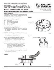
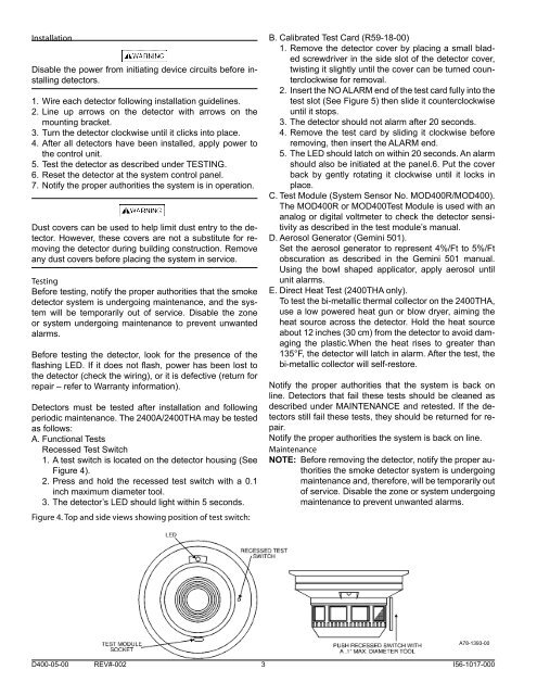
Recessed Test Switch<br />
1. A test switch is located on the detector housing (See<br />
Figure 4).<br />
2. Press <strong>and</strong> hold the recessed test switch with a 0.1<br />
inch maximum diameter tool.<br />
3. The detector’s LED should light within 5 seconds.<br />
Figure 4. Top <strong>and</strong> side views showing position of test switch:<br />
B. Calibrated Test Card (R59-18-00)<br />
1. Remove the detector cover by placing a small bladed<br />
screwdriver in the side slot of the detector cover,<br />
twisting it slightly until the cover can be turned counterclockwise<br />
for removal.<br />
2. Insert the NO ALARM end of the test card fully into the<br />
test slot (See Figure 5) then slide it counterclockwise<br />
until it stops.<br />
3. The detector should not alarm after 20 seconds.<br />
4. Remove the test card by sliding it clockwise before<br />
removing, then insert the ALARM end.<br />
5. The LED should latch on within 20 seconds. An alarm<br />
should also be initiated at the panel.6. Put the cover<br />
back by gently rotating it clockwise until it locks in<br />
place.<br />
C. Test Module (System Sensor No. MOD400R/MOD400).<br />
The MOD400R or MOD400Test Module is used with an<br />
analog or digital voltmeter to check the detector sensitivity<br />
as described in the test module’s manual.<br />
D. Aerosol Generator (Gemini 501).<br />
Set the aerosol generator to represent 4%/Ft to 5%/Ft<br />
obscuration as described in the Gemini 501 manual.<br />
Using the bowl shaped applicator, apply aerosol until<br />
unit alarms.<br />
E. <strong>Direct</strong> Heat Test (<strong>2400THA</strong> only).<br />
To test the bi-metallic thermal collector on the <strong>2400THA</strong>,<br />
use a low powered heat gun or blow dryer, aiming the<br />
heat source across the detector. Hold the heat source<br />
about 12 inches (30 cm) from the detector to avoid damaging<br />
the plastic.When the heat rises to greater than<br />
135°F, the detector will latch in alarm. After the test, the<br />
bi-metallic collector will self-restore.<br />
Notify the proper authorities that the system is back on<br />
line. <strong>Detectors</strong> that fail these tests should be cleaned as<br />
described under MAINTENANCE <strong>and</strong> retested. If the detectors<br />
still fail these tests, they should be returned for repair.<br />
Notify the proper authorities the system is back on line.<br />
Maintenance<br />
NOTE: Before removing the detector, notify the proper authorities<br />
the smoke detector system is undergoing<br />
maintenance <strong>and</strong>, therefore, will be temporarily out<br />
of service. Disable the zone or system undergoing<br />
maintenance to prevent unwanted alarms.<br />
A78-1393-00<br />
D400-05-00 REV#-002 3 I56-1017-000