DH100ACDCI Ionization Air Duct Smoke Detector - System Sensor ...
DH100ACDCI Ionization Air Duct Smoke Detector - System Sensor ...
DH100ACDCI Ionization Air Duct Smoke Detector - System Sensor ...

Create successful ePaper yourself
Turn your PDF publications into a flip-book with our unique Google optimized e-Paper software.
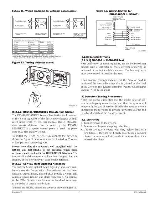
Figure 11. Wiring diagrams for optional accessories:<br />
ALARM SIGNAL (+)<br />
AUX POWER (–)<br />
DUCT DETECTOR<br />
<strong>DH100ACDCI</strong><br />
15<br />
20<br />
Figure 13. Testing detector alarm:<br />
(+)<br />
(–)<br />
PA400 (OPTIONAL)<br />
AUDIBLE ALERT<br />
ALARM SIGNAL (+)<br />
AUX POWER (–)<br />
DUCT DETECTOR<br />
<strong>DH100ACDCI</strong><br />
ACCESSORY CURRENT LOADS AT 24 VDC<br />
DEVICE<br />
APA451<br />
PA400<br />
RA400Z<br />
RTS451/RTS451KEY<br />
SSK451<br />
STANDBY<br />
12.5mA Max.<br />
0mA<br />
0mA<br />
12mA*<br />
5mA Max.<br />
TROUBLE<br />
n/a<br />
n/a<br />
n/a<br />
n/a<br />
9mA Max.<br />
ALARM<br />
30mA Max.<br />
15mA Max.<br />
10mA Max.<br />
7.5mA Max.<br />
30mA Max.<br />
*NOTE: When a unit is powered at the 120VAC or 220/240VAC input, any<br />
combination of accessories may be used such that the given accessory loads are:<br />
60 mA or less in the standby state; 110 mA or less in the alarm state.<br />
15<br />
20<br />
(+)<br />
(–)<br />
RED<br />
RA400Z (OPTIONAL)<br />
REMOTE (LED)<br />
ANNUNCIATOR<br />
A78-2692-00<br />
Figure 12. Wiring diagram for<br />
<strong>DH100ACDCI</strong> to SSK451<br />
COMMON 3<br />
TEMPORAL SELECT 2<br />
ALARM SIGNAL 1<br />
SUPERVISORY SIGNAL 4<br />
SSK451<br />
RESET 7<br />
TEST 8<br />
POWER (-) 6<br />
POWER (+) 5<br />
FIELD INSTALLED<br />
JUMPER FOR<br />
TEMPORAL PATTERN<br />
15 ALARM SIGNAL<br />
3<br />
NO<br />
14<br />
2 RESET<br />
11 TEST<br />
20 AUX. POWER (-)<br />
19 AUX. POWER (+)<br />
FIELD INSTALLED<br />
JUMPER<br />
SUPERVISORY<br />
CONTACT<br />
<strong>DH100ACDCI</strong><br />
A78-2693-00<br />
[6.2.3] Sensitivity Tests<br />
[6.2.3.1] MOD400 or MOD400R Test<br />
After verification of alarm capability, use the MOD400R test<br />
module with a voltmeter to check detector sensitivity as<br />
indicated in the test module’s manual. The housing cover<br />
must be removed to perform this test.<br />
If test module readings indicate that the detector head is<br />
outside of the acceptable range that is printed on the label<br />
of the detector, the detector chamber requires cleaning per<br />
Section [7] of this manual.<br />
A78-2694-00<br />
[6.2.2.2] RTS451/RTS451KEY Remote Test Station<br />
The RTS451/RTS451KEY Remote Test Station facilitates test<br />
of the alarm capability of the duct smoke detector as indicated<br />
in the RTS451/RTS451KEY manual. The <strong>DH100ACDCI</strong><br />
duct smoke detector can be reset by the RTS451/<br />
RTS451KEY. If a system control panel is used, the panel<br />
itself may also require testing.<br />
To install the RTS451/RTS451KEY, connect the device as<br />
shown in Figure 9; wire runs must be limited to 25 ohms<br />
or less per interconnecting wire.<br />
Please note that the magnetic coil supplied with the<br />
RTS451 and RTS451KEY is not required when these<br />
accessories are used with the <strong>DH100ACDCI</strong> detectors. The<br />
functionality of the magnetic coil has been designed into the<br />
circuitry of the new Innovair duct smoke detectors.<br />
[6.2.2.3] SSK451 Multi-Signaling Accessory<br />
The <strong>System</strong> <strong>Sensor</strong> SSK451 Multi-Signaling accessory combines<br />
a sounder feature with a key activated test and reset<br />
function. Green, amber, and red LEDs provide a visual indication<br />
of power, trouble, and alarm respectively. An optional<br />
strobe (PS24LO) with a smoke lens can be added to conform<br />
to the codes of certain jurisdictions.<br />
To install the SSK451, connect the device as shown in figure 12.<br />
[7] <strong>Detector</strong> Cleaning Procedures<br />
Notify the proper authorities that the smoke detector system<br />
is undergoing maintenance, and that the system will<br />
temporarily be out of service. Disable the zone or system<br />
undergoing maintenance to prevent unwanted alarms and<br />
possible dispatch of the fire department.<br />
[7.1] <strong>Air</strong> Filters<br />
1. Turn off power to the system.<br />
2. Remove and inspect sampling tube filters.<br />
3. If filters are heavily coated with dirt, replace them with<br />
new filters. If they are not heavily coated, use a vacuum<br />
cleaner or compressed air nozzle to remove dust, then<br />
reinstall the filters.<br />
D100-68-00 7 I56-1684-06R