FP 400E-1M - Bermad
FP 400E-1M - Bermad
FP 400E-1M - Bermad

Create successful ePaper yourself
Turn your PDF publications into a flip-book with our unique Google optimized e-Paper software.
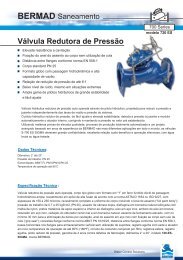
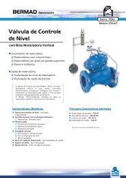
BERMAD Fire Protection<br />
400 Series<br />
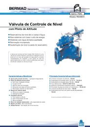
Hydraulically Controlled<br />
Deluge Valve<br />
with EasyLock Manual Reset<br />
Model: <strong>FP</strong> <strong>400E</strong>-<strong>1M</strong><br />
Typical Applications<br />
Features and Benefits<br />
■ Latch open – Closes upon local reset only<br />
Automatic spray or foam systems<br />
Petrochemical facilities<br />
■ One-piece molded elastomeric moving part –<br />
No maintenance required<br />
■ Simple design – Cost effective<br />
■ Obstacle-free full-bore – Uncompromising reliability<br />
■ Factory pre-assembled trim – Out-of-box quality<br />
■ In-line serviceable – Minimal down time<br />
Flammable materials storage<br />
Gas storage tanks<br />
Optional Features<br />
■ Water motor alarm<br />
■ Alarm pressure-switch (code: P or P7)<br />
■ Seawater service (add FS as prefix to model)<br />
■ Valve Position Single/Double Limit Switches<br />
Hydraulic remote controlled systems
BERMAD Fire Protection<br />
Model: <strong>FP</strong> <strong>400E</strong>-<strong>1M</strong><br />
400 Series<br />
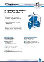
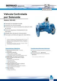
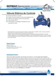
Operation<br />
The BERMAD Model <strong>FP</strong> <strong>400E</strong>-<strong>1M</strong> is suitable for systems that include wet pilot lines with closed fusible plugs (thermal<br />
releases), and piping systems with a wide variety of open nozzles. The typical wet pilot line is installed in a covered<br />
area and connected to the valve trim.<br />
In the SET position, the line-pressure supplied to the main valve’s control chamber [1] via the priming<br />
line [2] and through an EasyLock Manual Reset [3], is trapped by the EasyLock internal check valve, by the closed wet<br />
pilot line [4], and by a closed Manual Emergency Release [5]. The trapped pressure holds the main valve’s diaphragm<br />
and plug against the valve seat [6], sealing it drip-tight and keeping the system piping dry.<br />
Under FIRE or TEST conditions, water is released from the control chamber through the opened thermal release [F]<br />
of the wet pilot line, or the Manual Emergency Release. The EasyLock prevents line-pressure from entering the control<br />
chamber, allowing the main valve to latch open and water to flow into the system piping and to the alarm device.<br />
[F]<br />
[4]<br />
[3]<br />
[6]<br />
[5]<br />
[2]<br />
[1]<br />
15B<br />
Valve Closed (set position)<br />
Valve Open (operating condition)<br />
Engineer Specifications<br />
■ The deluge valve shall be a UL-Listed, hydraulically controlled, elastomeric type globe valve with a rolling-diaphragm.<br />
■ The valve shall have an unobstructed flow path with no stem guide or supporting ribs.<br />
■ Valve actuation shall be accomplished by a fully peripherally supported, one-piece balanced rolling-diaphragm,<br />
vulcanized with a rugged radial seal disk. The diaphragm assembly shall be the only moving part.<br />
■ The valve shall have a removable cover for quick in-line service enabling all necessary inspection and servicing.<br />
■ The control trim materials shall consist of S.S.316 tubing and fittings, and plated brass accessories including local<br />
EasyLock Manual Reset, Y Strainer and Manual Emergency Release.<br />
■ The control trim shall be supplied as an assembly, pre-assembled and hydraulically tested at an ISO 9000 and 9001<br />
certified factory.<br />
■ The Hydraulically Controlled Deluge Valve shall latch open in response to activation of a releasing device.<br />
The valve shall reset to the closed position, only upon local manual activation of the reset device.
BERMAD Fire Protection<br />
Model: <strong>FP</strong> <strong>400E</strong>-<strong>1M</strong><br />
400 Series<br />
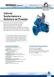
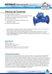
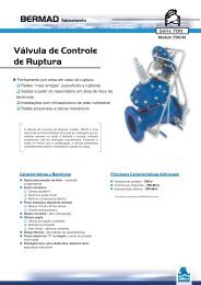
System Components<br />
1 - Main Valve, <strong>FP</strong> <strong>400E</strong> Series<br />
2A - Gauge Valve<br />
3A - Pressure Gauge<br />
4B - Priming Strainer<br />
5A - Drain Valve<br />
11A - Alarm Shutoff Valve<br />
14A - Check Valve<br />
15B - Manual Emergency Release<br />
18B - Priming Ball Valve<br />
19B - Drip Check<br />
M - EasyLock Manual Reset<br />
Optional<br />
P - Pressure Switch<br />
W - Water Motor Assembly<br />
S - Valve Position Limit Switch / Switches<br />
11A<br />
3A<br />
1<br />
19B<br />
14A<br />
2A<br />
M<br />
3A<br />
5A<br />
15B<br />
2A<br />
18B<br />
4B<br />
UL Listed<br />
The BERMAD Model <strong>FP</strong> <strong>400E</strong>-<strong>1M</strong> is<br />
UL-Listed when installed<br />
with specific components and accessories.<br />
Hydraulic<br />
Atmosphere
BERMAD Fire Protection<br />
Model: <strong>FP</strong> <strong>400E</strong>-<strong>1M</strong><br />
400 Series<br />
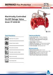
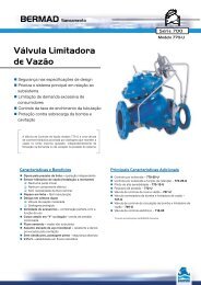
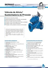
Technical Data<br />
TI<br />
Dv<br />
L 1<br />
L 4<br />
Th<br />
Tb<br />
Ts<br />
Tw<br />
Size<br />
1½”, 2” 2½” 3” 4” 6” 8” 10” 12”<br />
mm inch mm inch mm inch mm inch mm inch mm inch mm inch mm inch<br />
Dimensions<br />
(1)<br />
L 1<br />
205 8 1 /16 205 8 1 /16 257 10 1 /8 320 12 5 /8 415 16 5 /16 500 19 11 /16 605 23 13 /16 725 28 9 /16<br />
(2)<br />
L 4<br />
205 8 1 /16 N/A N/A 250 9 13 /16 320 12 5 /8 415 16 5 /16 500 19 11 /16 N/A N/A N/A N/A<br />
TI 142 5 5 /8 142 5 5 /8 119 4 11 /16 84 3 5 /16 57 2 1 /4 - - - - - -<br />
Tw 228 9 220 8 11 /16 243 9 9 /16 253 10 312 12 5 /16 326 12 13 /16 346 13 5 /8 391 15 3 /8<br />
Ts 228 9 220 8 11 /16 243 9 9 /16 253 10 318 12 1 /2 326 12 13 /16 326 12 13 /16 391 15 3 /8<br />
Th 226 8 7 /8 242 9½ 262 10 5 /16 261 10 5 /16 356 14 407 16 407 16 546 21 1 /2<br />
Tb 278 10 1 /16 289 11 3 /8 300 11 13 /16 337 13 1 /4 378 14 7 /8 405 15 15 /16 413 16 1 /4 473 18 5 /8<br />
Dv Ø ¾” 1½” 1½” 2” 2” 2” 2” 2”<br />
Notes:<br />
1. L 1<br />
is for flanged ANSI #150 and ISO PN16.<br />
2. L 4<br />
is for grooved end connections (Ductile Iron Only).<br />
3. Provide adequate space around valve for maintenance.<br />
4. Data is for envelope dimensions, specific component<br />
positioning may vary.<br />
250 (75)<br />
Wet Pilot line Maximum Elevation Above Valve<br />
<strong>Bermad</strong> <strong>400E</strong> with EasyLock Manual Reset<br />
Connection Standard<br />
• Flanged: ANSI B16.42 (Ductile Iron),<br />
B16.5 (Steel & Stainless Steel),<br />
B16.24 (Bronze) or ISO PN16<br />
• Grooved: ANSI/AWWA C606 for 2, 3, 4, 6 & 8"<br />
Water Temperature<br />
• 0.5 – 50°C (33 – 122°F)<br />
Available Sizes<br />
• 1½, 2, 2½, 3, 4, 6, 8, 10 & 12"<br />
• UL-Listed for sizes 1½, 2, 2½, 3, 4, 6, 8 & 10"<br />
Pressure Rating<br />
• Max. working pressure: 250 psi (17 bar)<br />
Height ft (m)<br />
200 (60)<br />
150 (45)<br />
100 (30)<br />
50 (15)<br />
0 (0)<br />
psi 20<br />
(bar) (1.3)<br />
40<br />
(2.7)<br />
60<br />
(4.1)<br />
80<br />
(5.5)<br />
100<br />
(6.8)<br />
11/2-2”<br />
120<br />
(8.2)<br />
6”<br />
140<br />
(9.6)<br />
160<br />
(11)<br />
21/2”<br />
175<br />
(12)<br />
200<br />
(13.8)<br />
3”<br />
8-12”<br />
225<br />
(15.5)<br />
4”<br />
250<br />
(17.2)<br />
Manufacturers Standard Materials<br />
Main valve body and cover<br />
• Ductile Iron ASTM A-536<br />
Main valve internals<br />
• Stainless Steel 304 & Cast Iron<br />
Control Trim System<br />
• Brass control components/accessories<br />
• Stainless Steel 316 tubing & fittings<br />
Elastomers<br />
• Nylon fabric reinforced polyisoprene NR<br />
Coating<br />
• Electrostatic Powder Coating Polyester,<br />
Red (RAL 3002)<br />
Optional Materials<br />
Main valve body<br />
• Carbon Steel ASTM A-216 WCB<br />
• Stainless Steel 316<br />
• Ni-Al-Bronze ASTM B-148<br />
Control Trim<br />
• Stainless Steel 316<br />
• Monel® and Ni-Al-Bronze<br />
• Hastalloy C-276<br />
Elastomers<br />
• NBR<br />
• EPDM<br />
Coating<br />
• High Build Epoxy Fusion-Bonded<br />
with UV Protection, Anti-Corrosion<br />
Inlet Pressure<br />
bermadfire@bermad.com • www.bermad.com<br />
The information herein is subject to change without notice. BERMAD shall not be held<br />
liable for any errors. All rights reserved. © Copyright by BERMAD. PE4PE-<strong>1M</strong> 11