Hesterberg GmbH - Chapter pipe drop hangers

You also want an ePaper? Increase the reach of your titles
YUMPU automatically turns print PDFs into web optimized ePapers that Google loves.
HESTERBERG<br />
Beschreibung der Rohrabhängungen<br />
Rohrabhängungen<br />
Pipe <strong>drop</strong> <strong>hangers</strong><br />
Description <strong>pipe</strong> <strong>drop</strong> <strong>hangers</strong><br />
1. Systematik<br />
1.1 Befestigungsart/Funktion<br />
1.1.1 Befestigungsart<br />
Als mögliche Befestigungsformen für Rohrabhängungen<br />
kommen grundsätzlich drei<br />
Varianten in Frage:<br />
1) Geklemmt, Form A und B<br />
Diese Ausführung erfordert bauseits<br />
den geringsten Montageaufwand, ist<br />
jedoch aufgrund der konstruktiven<br />
Auslegung an das mit der Bestellung<br />
zugeordnete Trägerprofil gebunden.<br />
Wegen der eingeschränkten Pendelmöglichkeit<br />
der Gewindeanschlußteile<br />
bzw. wegen der Axialverschiebungsrichtung<br />
sind die beiden Ausführungen<br />
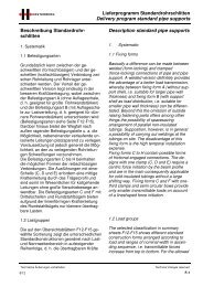
„Rohr senkrecht zum vorh. Trägerprofil“<br />
(Standardausführung) sowie<br />
„Rohr parallel zum vorh. Trägerprofil“<br />
(Bestellnummer um den Zusatz<br />
„X“ ergänzt) möglich (s. Abb. 1).<br />
1. Systematic<br />
1.1 Fixing form/function<br />
1.1.1 Fixing form<br />
Basically three variants of <strong>pipe</strong> <strong>drop</strong> <strong>hangers</strong><br />
come into consideration as possible fixing<br />
forms:<br />
1) Clamped, form A and B<br />
This version requires the least installa<br />
tion expense on the part of the<br />
construction, but is, however, by the<br />
reason of the constructive set up tied to<br />
the coordinated beam profile. Both versions<br />
„<strong>pipe</strong> vertical to the present beam<br />
profile“ (standard version) as well as<br />
„<strong>pipe</strong> parallel to the beam profile“<br />
(order number extended with index<br />
„X“ ) are possible (see figure 1), due to<br />
the limited possibility of reciprocating<br />
movement of the threaded joining parts<br />
and due to the axial shifting direction,<br />
respectively.<br />
Abb. 1: a) Rohrleitung quer zum Trägerprofil b) Rohrleitung parallel zum Trägerprofil<br />
Figure 1: a) <strong>pipe</strong> cross to the beam<br />
b) <strong>pipe</strong> parallel to the beam<br />
Technische Änderungen vorbehalten.<br />
8/12<br />
Technical changes reserved.<br />
K-1
Rohrabhängungen<br />
Pipe <strong>drop</strong> <strong>hangers</strong><br />
2) Geschweißt, Form C und D<br />
Diese Hängerausführungen sind mit<br />
Anschweißlaschen ausgerüstet. Die<br />
höhere Flexibilität in der Anwendung<br />
ist allerdings mit einem nicht unerheblichen<br />
Montageaufwand (Schweißnahtvorbereitung,<br />
Schweißen, Erneuerung<br />
der Korrosionsschutzschichten)<br />
verbunden.<br />
3) Nur Gewindeanschluß, Form E<br />
Durch den Wegfall entsprechender<br />
Befestigungsteile ist diese Ausführung<br />
für die Befestigung mit einer<br />
Durchgangsbohrung vorgesehen. Axiale<br />
Bewegungen der Rohrleitung sind<br />
bei dieser Bauform nicht zulässig.<br />
Durch den Einsatz von Kugelscheiben/Kugelpfannen<br />
kann erforderlichenfalls<br />
eine beschränkte Pendelbewegung<br />
ohne zusätzliche Momentenbelastung<br />
der Gewindestange ermöglicht<br />
werden (s. Abb. 2).<br />
HESTERBERG<br />
2) Welded , form C and D<br />
These <strong>drop</strong> hanger designs are<br />
equipped with welding straps. This<br />
higher flexibility in the application,<br />
however, is connected with a considerrable<br />
installation expense (preparation<br />
weld, welding, renewal of the protective<br />
corrosion coating).<br />
3)Threaded joint only, form E<br />
Due to the omission of the appropriate<br />
fixing parts, this version is provided for<br />
a fastening by means of a through bore<br />
hole. Axial movements of the <strong>pipe</strong> are<br />
not allowed when using this version.<br />
The use of spherical disc /ball socket<br />
renders, if necessary, a limited reciprocating<br />
movement without additional<br />
load of moments on the threaded rod<br />
(see figure 2).<br />
Spherical disc<br />
Ball socket<br />
Beam profile<br />
Abb. 2 :<br />
Pendelbewegung ohne Momentenbelastung<br />
der Gewindestange unter Einsatz<br />
von Kugelscheibe und Kugelschale<br />
Figure 2 :<br />
reciprocating movement without load of<br />
moments on the threaded rod by using<br />
spherical disc / ball socket<br />
Technische Änderungen vorbehalten.<br />
K-2<br />
Technical changes reserved.<br />
8/12
HESTERBERG<br />
Rohrabhängungen<br />
Pipe <strong>drop</strong> <strong>hangers</strong><br />
1.1.2 Funktion<br />
Bedingt durch den Einsatz einer Gewindestange<br />
und entsprechenden Anschlußteilen<br />
(Gewindebügel, Gewindeöse) zur Kraftübertragung<br />
ist eine Belastung der Rohrabhängungen<br />
nur in positiver z-Richtung möglich.<br />
In den Anwendungsfällen, in denen eine axiale<br />
Bewegung der Rohrleitung (z. B. bedingt<br />
durch Temperaturschwankungen) gewährleistet<br />
werden muss, ist die Form B oder D zu<br />
wählen (s. Abb. 3).<br />
1.1.2 Function<br />
Conditional on the use of a threaded rod and<br />
its appropriate joint parts (threaded bow,<br />
threaded eye) for the force transmission a<br />
load of the tube <strong>drop</strong> hanger is only possible<br />
in positive z-direction. In the applications in<br />
which an axial movement of the tubing<br />
(e.g. conditional on temperature oscillations)<br />
has to be guaranteed, the form B or D has to<br />
be selected (see figure 3).<br />
Abb. 3 : Axialer Verschiebeweg bei Form B und D<br />
Figure 3 : Axial shifting way for form B and D<br />
1.2 Bauform/Lastgruppe<br />
Die Unterscheidung der in den Zeilen des<br />
Übersichtsblattes wiedergegebenen Bauformen<br />
ergibt sich aus der Bauart der rohrumschließenden<br />
Teile sowie der möglichen Belastungen<br />
in aufsteigender Reihenfolge. Die<br />
Bauformen H10 und H20 bieten durch die<br />
Verwendung von Rohrschellen nach DIN<br />
3567, Form A in Verbindung mit Befestigungslaschen<br />
ein universelles Lösungskonzept<br />
für alle Anwendungsfälle bei isolierten<br />
und unisolierten Rohrleitungen und Standardbelastungen.<br />
Die Halterung kann durch<br />
Verlängerung der Befestigungslasche an die<br />
1.2 Construction form /load group<br />
The differenciation of the construction forms<br />
interpreted in the particular summary sheet<br />
lines results from the mounting form of the<br />
<strong>pipe</strong> enclosing parts as well as the possible<br />
loads in ascending sequence. The construction<br />
forms H10 and H20 provide a universal<br />
solution concept for all applications with insulated<br />
and non-insulated tubings and standard<br />
loads by use of <strong>pipe</strong> clamps in compliance<br />
with DIN 3567, form A in connection<br />
with fixing straps. The retaining can be adjusted<br />
to required insulating power through<br />
extension of the fixing strap. When using in-<br />
Technische Änderungen vorbehalten.<br />
8/12<br />
Technical changes reserved.<br />
K-3
Rohrabhängungen<br />
Pipe <strong>drop</strong> <strong>hangers</strong><br />
erforderliche Isolierstärke angepasst werden.<br />
Bei isolierten Rohrleitungen im Außenbereich<br />
kann bei Bedarf eine Schutzhaube<br />
das Eindringen von Wasser in die Isolierung<br />
verhindern (s. Abb. 4).<br />
HESTERBERG<br />
sulated <strong>pipe</strong>s in outside areas, a protection<br />
cap avoids the penetration of water into the<br />
isolation (see figure 4).<br />
Insulation<br />
thickness<br />
Protection cap<br />
Fixing strap<br />
Insulation<br />
Abb. 4 :<br />
Montagebeispiel Bauform H10/H20<br />
Figure 4 :<br />
Mounting example construction form<br />
H10/H20<br />
1.3 Zulässige Belastungen<br />
Alle Lastangaben beziehen sich auf einen<br />
Einsatztemperaturbereich bis 100°C ausgehend<br />
von Rohrlagern der Werkstoffgruppe 1.<br />
Die sich aus den Werkstoffgruppen 2-7 speziell<br />
im Zusammenhang mit abweichenden<br />
Einsatztemperaturen ergebenden von den<br />
Tabellenwerten abweichenden Belastbarkeiten<br />
sind im Einzelfall zu erfragen.<br />
1.3 Allowed loads<br />
All load statements refer to an operable temperature<br />
range until 100°C starting from <strong>pipe</strong><br />
supports of material group 1. The varying<br />
loading capacities especially in connection<br />
with differing temperatures of application, if<br />
not stated in the table for the material groups<br />
2-7, are to be found out in particular cases.<br />
Technische Änderungen vorbehalten.<br />
K-4<br />
Technical changes reserved.<br />
8/12
HESTERBERG<br />
Rohrabhängungen<br />
Pipe <strong>drop</strong> <strong>hangers</strong><br />
2. Einsatzbereiche<br />
2. Range of application<br />
2.1 Konstruktive Parameter<br />
Sowohl die geschweißten (Befestigungsformen<br />
C+D) als auch die geklemmten<br />
(Befestigungsformen A, B+E) Rohrabhängungen<br />
eignen sich zur Anbringung an alle<br />
handelsüblichen Profile. Die im Falle einer<br />
Klemmbefestigung zusätzlich benötigten<br />
Maße sind auf der Abb. 5 im Einzelnen dargestellt.<br />
2.1 Constructive parameters<br />
The welded (fixing forms C+D) as well as the<br />
clamped (fixing forms A,B+E) tube <strong>drop</strong><br />
<strong>hangers</strong> are suitable for mounting on all<br />
standard profiles. The additional required<br />
dimensions in case of a clamp fixing are<br />
shown in particular, in figure 5.<br />
Beam flange thickness<br />
Beam clamping<br />
Location plate<br />
Shim for adjusting the beam<br />
flange<br />
Beam width<br />
Abb. 5 :<br />
Trägerklemmbefestigung mit erforderlichen<br />
Abmessungen und Bauteilen<br />
Figure 5 :<br />
Beam clamp fixing with required dimensions<br />
and mounting parts<br />
Bei der Form E sind je nach vorhandenem<br />
Stahlbauprofil unterschiedliche Zubehörteile<br />
erforderlich (Beispiele s. Abb. 6).<br />
Depending on the present structural steel<br />
profile for form E different accessories are<br />
required (example see figure 6).<br />
Abb. 6 :<br />
Zuberhörteile<br />
Figure 6 :<br />
accessories<br />
Square washer<br />
DIN 435<br />
Spherical disc<br />
Ball socket<br />
Square washer<br />
DIN 434<br />
a) b) c)<br />
a) Einspannmomentenfreie Hängerbefestigung Form<br />
E an Parallelflanschträger<br />
b) Hängerbefestigung Form E an U-Profil<br />
c) Hängerbefestigung Form E an I-Profil<br />
a) restraining moment free <strong>drop</strong> hanger fastening<br />
form E on parallel flange girder<br />
b) <strong>drop</strong> hanger fastening form E on U-profile<br />
c) <strong>drop</strong> hanger fastening form E on I-profile<br />
Technische Änderungen vorbehalten.<br />
8/12<br />
Technical changes reserved.<br />
K-5
Rohrabhängungen<br />
Pipe <strong>drop</strong> <strong>hangers</strong><br />
HESTERBERG<br />
2.2 Einsatztemperaturen<br />
Die möglichen Einsatztemperaturen für die<br />
zur Verfügung stehenden Werkstoffkombinationen<br />
können dem Werkstoffgruppenblatt<br />
entnommen werden. Bei den angegebenen<br />
Maximalwerten handelt es sich um die Temperaturen<br />
im Rohrschellenbereich. Der<br />
Einsatztemperaturbereich (in der Regel<br />
außerhalb der Isolierung liegenden) der Gewindeteile<br />
und Anschlußplatten liegt zwischen<br />
-15°C und 300°C. Eine Erweiterung<br />
nach Oben oder Unten ist im Bedarfsfall<br />
durch den Einsatz anderer Werkstoffe möglich.<br />
2.2 Temperatures of application<br />
The possible temperatures of application for<br />
the available material combination can be<br />
taken from the material group sheet. The<br />
stated maximum values are identical with<br />
the temperatures in the <strong>pipe</strong> clamp range.<br />
The operable temperature range (in general<br />
being outside the isolation) of the threaded<br />
parts and joining plate ranges between -15°<br />
C and 300°C. By using other materials an<br />
extension towards the top or the bottom is<br />
possible on demand.<br />
3. Werkstoffe<br />
3.1 Rohrschellen<br />
Auf der Seite 4 sind die gängigsten Werkstoffkombinationen<br />
mit Ihren jeweiligen Temperatureinsatzbereichen<br />
zusammengefasst.<br />
Darüber hinaus besteht die Möglichkeit, z. B.<br />
bei Edelstahlrohren zur Vermeidung von<br />
Kontaktkorrosion oder bei beschichteten<br />
Rohrleitungen zum Schutz der Lackierung<br />
elastische Schelleneinlagen (s. Kap. Zubehör)<br />
vorzusehen. Die sich aus den Werkstoffgruppen<br />
2-7 speziell im Zusammenhang<br />
mit abweichenden Einsatztemperaturen ergebenden<br />
von den Tabellenwerten abweichenden<br />
Belastbarkeiten sind im Einzelfall<br />
zu erfragen.<br />
3. Materials<br />
3.1 Pipe clamps<br />
The most current material combinations with<br />
their corresponding operable temperature<br />
ranges are summarised on page 5<br />
Beyond this there is the possibility to provide<br />
elastical clamp insertions, e.g. for high quality<br />
steel <strong>pipe</strong>s in order to avoid contact corrosion<br />
or for coated tubing in order to protect<br />
the varnish (see chapter accessories). The<br />
values for material groups 2-7 resulting from<br />
deviating load capacities especially in coherence<br />
with deviating temperatures of application<br />
are to ask for in particular.<br />
3.2 Gewindeteile<br />
Gewindestangen, Zugstangen und alle außerhalb<br />
der Rohrschelle angeordneten<br />
Schrauben werden standardmäßig in der<br />
Qualität 4.6 ausgeführt (Schrauben und Muttern<br />
feuerverzinkt, Gewindestangen galvanisch<br />
verzinkt). Alle übrigen Gewindenormteile<br />
wie Gewindeösen, Gewindebügel,<br />
Spannschlösser etc. sind aus C-Stahl, galvanisch<br />
verzinkt, gefertigt.<br />
3.2 Threaded parts<br />
Threaded rods, towing bar and all exterior<br />
from the <strong>pipe</strong> clamp arranged screws will be<br />
designed according to the standard in<br />
strength classification 4.6 (screws and nuts<br />
hotgalvanized, threaded rods coldgalvanized).<br />
All remaining threaded standard<br />
parts like threaded eyes, threaded bows,<br />
tension locks etc. are made of C-steel, coldgalvanized.<br />
Technische Änderungen vorbehalten.<br />
K-6<br />
Technical changes reserved.<br />
8/12
HESTERBERG<br />
Rohrabhängungen<br />
Pipe <strong>drop</strong> <strong>hangers</strong><br />
3.3 Anschlußplatten<br />
Standardwerkstoff für Anschlußplatten in geschweißter<br />
oder geklemmter Ausführung ist<br />
S235 JR. Als Beschichtung kommen grundsätzlich<br />
alle Varianten gemäß Tabellenblatt<br />
„Beschichtungssystem“ (Seite 6) in Frage.<br />
Für alle Anschweißlaschen empfiehlt sich jedoch<br />
der besseren Montierbarkeit wegen die<br />
Ausführung „roh“ oder „grundiert“.<br />
4. Zubehör<br />
Für unterschiedliche Anwendungsfälle (s.<br />
Abb. 7) stehen spezielle Schelleneinlagen<br />
zur Verfügung.<br />
3.3 Locating plate<br />
The locating plates in welded and clamped<br />
version are made of S235 JR in accordance<br />
to standard. Basically all variants according<br />
to table sheet „coating system“ (page 7) can<br />
be considered as coating. For the welding<br />
straps it is recommended, however, to use<br />
version „raw“ or „primed“ due to the better<br />
ability of mounting.<br />
4. Accessories<br />
For different applications (see figure 7) special<br />
clamp insertions are available.<br />
Werkstoff<br />
Dicke<br />
Einsatztemperatur<br />
bevorzugter<br />
Anwendungsfall<br />
Montage/Lieferform<br />
Material Thickness Temperature of Preferable application<br />
application<br />
EPDM 1 mm -50° - 120°C Vermeidung von<br />
Kontaktkorrosion<br />
Avoidance of contact<br />
corrosion<br />
EPDM 2 mm - 6 mm -50° - 120°C Geräuschdämmung,<br />
Körperschallentkopplung<br />
Silencing, impact sound<br />
neutralisation<br />
SGC 2 mm -90°- 250°C Vermeidung von<br />
Kontaktkorrosion,<br />
Geräuschdämmung<br />
Avoidance of contact<br />
corrosion. silencing<br />
It 2 mm - 5 mm -40° - 400°C Thermische Trennung<br />
Thermal separation<br />
Installation / delivery form<br />
½-Rohrumfang<br />
geklebt; lose Meterware<br />
o. Fixlänge<br />
½-tube periphery<br />
adhered, loose (cut goods<br />
or fixed length)<br />
½-Rohrumfang<br />
geklebt; lose Meterware<br />
o. Fixlänge<br />
½-tube periphery<br />
adhered, loose (cut goods<br />
or fixed length)<br />
lose Meterware o.<br />
Fixlänge<br />
loose (cut goods or fixed<br />
length)<br />
lose Meterware<br />
loose (cut goods)<br />
Glasfaserband<br />
Glas fibre strap<br />
5 mm -15° - 550°C Thermische Trennung<br />
Thermal separation<br />
lose Meterware<br />
loose (cut goods)<br />
Abb. 7 :<br />
Gängige Rohrschelleneinlage mit ihren<br />
Einsatzbereichen<br />
Figure 7 :<br />
Current tube clamp inlay with its range of<br />
applications<br />
Technische Änderungen vorbehalten.<br />
8/12<br />
Technical changes reserved.<br />
K-7
Rohrabhängungen<br />
Pipe <strong>drop</strong> <strong>hangers</strong><br />
HESTERBERG<br />
Da je nach Rohraußendurchmesser und Dicke<br />
der Einlage eine Anpassung des Rohrschellendurchmessers<br />
erforderlich ist, sollte<br />
auch hier die Zuordnung schon bei der<br />
Bestellung getroffen werden. Je nach Art der<br />
Einlage kann diese vormontiert (geklebt)<br />
oder lose mitgeliefert werden. Alle Standardrohrabhängungen<br />
verstehen sich inkl. dem<br />
notwendigen Befestigungsmaterial, d. h. inkl.<br />
Schrauben, Muttern, Bolzen sowie sonstigen<br />
Befestigungselementen. Darüber hinaus benötigte<br />
Bauteile wie Unterlegscheiben,<br />
Schrägscheiben, Kugelschalen etc. können<br />
gesondert (s. Kap. Zubehör) bestellt werden.<br />
Since an adjustment of the <strong>pipe</strong> clamp diameter<br />
is necessary depending on <strong>pipe</strong> outside<br />
diameter and thickness of insertion,<br />
decision should already be made with the<br />
order. Depending on the kind of insertion, it<br />
can be delivered pre-mounted (adhered) or<br />
lose. All standard <strong>pipe</strong> <strong>drop</strong> <strong>hangers</strong> are to<br />
be considered incl. the required fastening<br />
elements, i.e. incl. screws, nuts, bolts as well<br />
as all other fastening elements. Beyond this,<br />
all required mounting parts like washers,<br />
swash plate, sperical discs etc. can be ordered<br />
particularly (see chapter accessories).<br />
5. Systematische Vorgehensweise zur Auswahl<br />
einer Rohrabhängung<br />
5.1 Checkliste „Rohrabhängung“<br />
5. Systematically proceeding for the selection<br />
of a <strong>pipe</strong> <strong>drop</strong> hanger<br />
5.1 Check list „<strong>pipe</strong> <strong>drop</strong> hanger“<br />
Nennweite/Rohraußendurchmesser :<br />
Nominal width/<strong>pipe</strong> outside diameter : ..................../.......................<br />
Abstand Trägerunterkante-Rohrmitte H :<br />
Distance bottom of steel to tube center H :<br />
Isolierstärke :<br />
Insulation thickness :<br />
Belastungen:<br />
Loads :<br />
....................... mm<br />
....................... mm<br />
Fz = ............... kN<br />
Axial verschiebbar: Ja Nein <br />
Axial shiftable : Yes No <br />
Rohrleitung parallel zum Trägerprofil : Ja Nein <br />
Tubing parallel to beam profile : Yes No <br />
Maximale Einsatztemperatur:<br />
Maximum temperature of application :<br />
.................°C<br />
Ausführung :<br />
geschweißt geklemmt <br />
Type : welded clamped <br />
Nur bei geklemmter Ausführung:<br />
Trägerprofil: .<br />
Only for clamped version :<br />
Beam profile : ..................................<br />
Technische Änderungen vorbehalten.<br />
K-8<br />
Technical changes reserved.<br />
8/12
HESTERBERG<br />
Rohrabhängungen<br />
Pipe <strong>drop</strong> <strong>hangers</strong><br />
Technische Änderungen vorbehalten.<br />
8/12<br />
Technical changes reserved.<br />
K-9
Rohrabhängungen<br />
Pipe <strong>drop</strong> <strong>hangers</strong><br />
HESTERBERG<br />
Zum Anklemmen<br />
For clamping on<br />
Zum Anklemmen,<br />
Axial verschiebbar<br />
For clamping on,<br />
axial shiftable<br />
Zum Anschweißen<br />
For welding on<br />
Lastgruppe 3<br />
Load group 3<br />
H50<br />
Lastgruppe 2<br />
Load group 2<br />
Lastgruppe 1<br />
Load group 1<br />
H40 H30<br />
H20<br />
H10<br />
Technische Änderungen vorbehalten.<br />
K-10<br />
Technical changes reserved.<br />
8/12
HESTERBERG<br />
Rohrabhängungen<br />
Pipe <strong>drop</strong> <strong>hangers</strong><br />
Zum Anschweißen,<br />
Axial verschiebbar<br />
For welding on,<br />
axial shiftable<br />
Zum Anschrauben<br />
For screwing down<br />
Ab Seite K24<br />
DN 15 bis 600<br />
Starting page K24<br />
DN 15 to 600<br />
Ab Seite K21<br />
DN 15 bis 600<br />
Starting page K21<br />
DN 15 to 600<br />
Ab Seite K18<br />
DN 15 bis 600<br />
Starting page K18<br />
DN 15 to 600<br />
Ab Seite K15<br />
DN 200 bis 600<br />
Starting page K15<br />
DN 200 to 600<br />
Ab Seite K12<br />
DN 15 bis 150<br />
Starting page K12<br />
DN 15 to 150<br />
Technische Änderungen vorbehalten.<br />
8/12<br />
Technical changes reserved.<br />
K-11
H10A<br />
H10B<br />
Rohrabhängung, geklemmt<br />
Pipe <strong>drop</strong> hanger, clamped<br />
Rohrabhängung, geklemmt, axial verschiebbar<br />
Pipe <strong>drop</strong> hanger, clamped, axial shiftable<br />
HESTERBERG<br />
H10A / H10B<br />
V<br />
H<br />
H10A<br />
S<br />
H10A<br />
H10B<br />
C<br />
B<br />
Hinweis:<br />
Die Darstellung entspricht der Standardausführung „Rohrleitung quer zur Trägerprofilachse“.<br />
Für den Anwendungsfall „Rohrleitung parallel zur Profilachse“ die Bestellnummer<br />
um den Buchstaben X erweitern.<br />
Notice:<br />
Projection corresponds to standard version „tubing cross to beam profile axle“. For<br />
application „tubing parallel to profile axle“, extension of order number by letter „X“.<br />
H10B<br />
Bestellnummer / order no.: H10A 89 P=? H=? S=? W=? O=? H10B 89 P=? H=? S=? V=? W=? O=?<br />
H10A<br />
H10B<br />
Nennweite ä. Rohr- Einbau- Isolier- Klemmplatte Klemm- Gewinde- Belastung Gewicht Verschiebe- Gewicht<br />
mm Zoll durchm. höhe stärke verbinder stange kN kg weg kg<br />
Nominal diam. Pipe Fitting Insulation Clamping plate Clamping Threaded Load Weight Shifting Weight<br />
mm Inch o.d. height thickness joint rod kN kg way kg<br />
NW NB D H S B C Fx Fy Fz V<br />
15 1/2“ 22 1576 100 90 P+56 4 x M12 M12 - - 5,5 4,2 80 4,4<br />
20 3/4“ 27 1579 100 90 P+56 4 x M12 M12 - - 5,5 4,2 80 4,4<br />
25 1“ 34 1582 100 90 P+56 4 x M12 M12 - - 5,5 4,2 80 4,4<br />
32 1 1/4“ 43 1587 100 90 P+56 4 x M12 M12 - - 5,5 4,3 80 4,4<br />
40 1 1/2“ 49 1590 100 90 P+56 4 x M12 M12 - - 5,5 4,3 80 4,5<br />
50 2“ 61 1599 100 100 P+56 4 x M12 M12 - - 6,9 4,8 80 4,9<br />
65 77 1607 100 100 P+56 4 x M12 M12 - - 6,9 4,9 80 5,0<br />
80 3“ 89 1613 100 100 P+56 4 x M12 M12 - - 6,9 5,0 80 5,1<br />
100 4“ 115 1670 100 100 P+56 4 x M12 M16 - - 10,0 8,6 80 8,9<br />
150 6“ 169 1697 100 100 P+56 4 x M12 M16 - - 8,5 9,1 80 9,3<br />
Bestehend aus: 2 x Gewindebügel, 1 x Spannschloß, 1 x Zugstange L=250 mm, 1 x Gewindestange (L = 1000 mm),<br />
1 x Rohrschelle mit Lasche, 1 x Befestigungsplatte inkl. Klemmverbinder.<br />
Description:<br />
2 x threaded bow, 1 x turnbuckle, 1 x tie rod L=250 mm, 1 x threaded rod (L = 1000 mm),<br />
1 x <strong>pipe</strong> clamp with lug, 1 x fixing strap incl. clamping joints.<br />
Technische Änderungen vorbehalten.<br />
K-12<br />
Technical changes reserved.<br />
8/12
HESTERBERG<br />
H10C / H10D<br />
Rohrabhängung, geschweißt<br />
Pipe <strong>drop</strong> hanger, welded<br />
Rohrabhängung, geschweißt, axial verschiebbar<br />
Pipe <strong>drop</strong> hanger, welded, axial shiftable<br />
H10C<br />
H10D<br />
C<br />
B<br />
C<br />
B<br />
V<br />
H<br />
H10C<br />
S<br />
H10C<br />
H10D<br />
H10D<br />
Bestellnummer / order no.: H10C 89 P=? H=? S=? W=? O=? H10D 89 P=? H=? S=? V=? W=? O=?<br />
H10C<br />
H10D<br />
Nennweite ä. Rohr- Isolier- Gewinde- Belastung Einbau- Anschweiß- Gewicht Einbau- Anschweiß- Gewicht<br />
mm Zoll durchm. stärke stange kN höhe ende kg höhe ende kg<br />
Nominal diam. Pipe Insulation Threaded Load Fitting Structural Weight Fitting Structural Weight<br />
mm Inch o.d. thickness rod kN height Welding lug kg height Welding lug kg<br />
NW NB D S Fx Fy Fz H B x t C H B x t C<br />
15 1/2“ 22 100 M12 - - 5,5 1566 64 x 10 76 3,1 1576 (64+V) x 76 3,3<br />
20 3/4“ 27 100 M12 - - 5,5 1569 64 x 10 76 3,1 1579 (64+V) x 76 3,3<br />
25 1“ 34 100 M12 - - 5,5 1572 64 x 10 76 3,2 1582 (64+V) x 76 3,3<br />
32 1 1/4“ 43 100 M12 - - 5,5 1577 64 x 10 76 3,2 1587 (64+V) x 76 3,4<br />
40 1 1/2“ 49 100 M12 - - 5,5 1580 64 x 10 76 3,2 1590 (64+V) x 76 3,4<br />
50 2“ 61 100 M12 - - 6,9 1589 64 x 10 76 3,7 1599 (64+V) x 76 3,8<br />
65 77 100 M12 - - 6,9 1597 64 x 10 76 3,7 1607 (64+V) x 76 3,9<br />
80 3“ 89 100 M12 - - 6,5 1603 64 x 10 76 3,8 1613 (64+V) x 76 4,0<br />
100 4“ 115 100 M16 - - 10,0 1658 64 x 12 76 6,7 1670 (64+V) x 76 6,9<br />
150 6“ 169 100 M16 - - 8,5 1685 64 x 12 76 7,1 1697 (64+V) x 76 7,4<br />
Bestehend aus: 1 x Anschweißlasche, 2 x Gewindebügel, 1 x Spannschloß, 1 x Zugstange L=250 mm,<br />
1 x Gewindestange (L = 1000 mm), 1 x Rohrschelle mit Lasche.<br />
Description:<br />
1 x welding lug, 2 x threaded bow, 1 x turnbuckle, 1 x tie rod L=250 mm,<br />
1 x threaded rod (L = 1000 mm), 1 x <strong>pipe</strong> clamp with lug.<br />
Technische Änderungen vorbehalten.<br />
8/12<br />
Technical changes reserved.<br />
K-13
H10E<br />
Rohrabhängung, geschraubt<br />
Pipe <strong>drop</strong> hanger, screwed<br />
HESTERBERG<br />
H10E<br />
H<br />
S<br />
Bestellnummer / order no.:<br />
H10E 89 P=? H=? S=? W=? O=?<br />
Nennweite ä. Rohr- Einbau- Isolier- Gewinde- Belastung Gewicht<br />
mm Zoll durchm. höhe stärke stange kN kg<br />
Nominal diam. Pipe Fitting Insulation Threaded Load Weight<br />
mm Inch o.d. height thickness rod kN kg<br />
NW NB D H S Fx Fy Fz<br />
15 1/2“ 22 1076 100 M12 - - 5,5 2,3<br />
20 3/4“ 27 1079 100 M12 - - 5,5 2,3<br />
25 1“ 34 1082 100 M12 - - 5,5 2,3<br />
32 1 1/4“ 43 1087 100 M12 - - 5,5 2,3<br />
40 1 1/2“ 49 1093 100 M12 - - 5,5 2,4<br />
50 2“ 61 1099 100 M12 - - 6,9 2,7<br />
65 77 1107 100 M12 - - 6,9 2,8<br />
80 3“ 89 1119 100 M12 - - 6,5 3,0<br />
100 4“ 115 1132 100 M16 - - 10,0 4,9<br />
150 6“ 169 1159 100 M16 - - 8,5 5,3<br />
Bestehend aus:<br />
Description:<br />
1 x Gewindebügel, 1 x Gewindestange (L = 1000 mm),<br />
1 x Rohrschelle mit Lasche.<br />
1 x threaded bow, 1 x threaded rod (L = 1000 mm),<br />
1 x <strong>pipe</strong> clamp with lug.<br />
Technische Änderungen vorbehalten.<br />
K-14<br />
Technical changes reserved.<br />
8/12
HESTERBERG<br />
H20A / H20B<br />
Rohrabhängung, geklemmt<br />
Pipe <strong>drop</strong> hanger, clamped<br />
Rohrabhängung, geklemmt, axial verschiebbar<br />
Pipe <strong>drop</strong> hanger, clamped, axial shiftable<br />
H20A<br />
H20B<br />
V<br />
H<br />
S<br />
H20A<br />
C<br />
L<br />
H20A<br />
L<br />
H20B<br />
B<br />
Hinweis:<br />
Die Darstellung entspricht der Standardausführung „Rohrleitung quer zur Trägerprofilachse“.<br />
Für den Anwendungsfall „Rohrleitung parallel zur Profilachse“ die Bestellnummer<br />
um den Buchstaben X erweitern.<br />
Notice:<br />
Projection corresponds to standard version „tubing cross to beam profile axle“. For<br />
application „tubing parallel to profile axle“, extension of order number by letter „X“.<br />
H20B<br />
Bestellnummer / order no.: H20A 508 P=? H=? S=? W=? O=? H20B 508 P=? H=? S=? V=? W=? O=?<br />
H20A H20B<br />
Nennweite ä. Rohr- Einbau- Isolier- Länge Klemm- Klemm- Gewinde- Belastung Gewicht Verschie- Gewicht<br />
mm Zoll durchm. höhe stärke platte verbinder stange kN kg beweg kg<br />
Nominal diam. Pipe Fitting Insulation Length Clamping Clamping Threaded Load Weight Shifting Weight<br />
mm Inch o.d. height thickness plate joint rod kN kg way kg<br />
NW NB D H S L B C Fx Fy Fz V<br />
200 8“ 220 1722 100 150 100 P + 72 4 x M16 M16 - - 13,0 13,7 80 13,9<br />
250 10“ 273 1793 100 150 100 P + 72 4 x M16 M16 - - 12,8 20,9 80 21,2<br />
300 12“ 324 1818 100 150 100 P + 72 4 x M16 M16 - - 11,4 22,1 80 22,4<br />
350 14“ 356 1834 100 150 120 P + 72 4 x M16 M16 - - 10,6 23,3 80 23,6<br />
400 16“ 407 2020 100 150 120 P + 72 4 x M16 M20 - - 16,0 36,7 80 36,9<br />
500 20“ 508 2070 100 150 120 P + 72 4 x M16 M20 - - 14,4 39,7 80 39,9<br />
600 24“ 610 2121 100 150 120 P + 88 4 x M20 M24 - - 26,0 66,2 80 68,5<br />
Bestehend aus: 2 x Gewindebügel, 1 x Spannschloß, 1 x Zugstange L=250 mm, 1 x Gewindestange (L = 1000 mm),<br />
2 x Rohrschelle mit Lasche, 1 x Befestigungsplatte inkl. Klemmverbinder.<br />
Description:<br />
2 x threaded bow, 1 x turnbuckle, 1 x tie rod L=250 mm, 1 x threaded rod (L = 1000 mm),<br />
2 x <strong>pipe</strong> clamp with lug, 1 x fixing strap incl. clamping joints.<br />
Technische Änderungen vorbehalten.<br />
8/12<br />
Technical changes reserved.<br />
K-15
H20C<br />
H20D<br />
Rohrabhängung, geschweißt<br />
Pipe <strong>drop</strong> hanger, welded<br />
Rohrabhängung, geschweißt, axial verschiebbar<br />
Pipe <strong>drop</strong> hanger, welded, axial shiftable<br />
HESTERBERG<br />
H20C / H20D<br />
B<br />
C<br />
C<br />
B<br />
V<br />
H<br />
S<br />
H20C<br />
L<br />
L<br />
H20C<br />
H20D<br />
H20D<br />
Bestellnummer / order no.: H20C 508 P=? H=? S=? W=? O=? H20D 508 P=? H=? S=? V=? W=? O=?<br />
H20C<br />
H20D<br />
Nennweite ä. Rohr- Einbau- Isolier- Länge Gewinde- Belastung Anschweiß- Gewicht Anschweiß- Gewicht<br />
mm Zoll durchm. höhe stärke stange kN ende kg ende kg<br />
Nominal diam. Pipe Fitting Insulation Length Threaded Load Structural Weight Structural Weight<br />
mm Inch o.d. height thickness rod kN welding lug kg welding lug kg<br />
NW NB D H S L Fx Fy Fz B x t C B x t C<br />
200 8“ 220 1710 100 150 M16 - - 13,0 64 x 12 76 11,5 (64+V) 76 11,7<br />
250 10“ 273 1778 100 150 M16 - - 12,8 64 x 15 76 17,7 (64+V) 76 18,0<br />
300 12“ 324 1803 100 150 M16 - - 11,4 64 x 15 76 18,9 (64+V) 76 19,2<br />
350 14“ 356 1819 100 150 M16 - - 10,6 64 x 15 76 20,1 (64+V) 76 20,4<br />
400 16“ 407 2005 100 150 M20 - - 16,0 64 x 15 76 31,8 (64+V) 76 32,1<br />
500 20“ 508 2055 100 150 M20 - - 14,4 64 x 15 76 34,8 (64+V) 76 35,1<br />
600 24“ 610 2106 100 150 M24 - - 26,0 64 x 15 76 63,3 (64+V) 76 65,5<br />
Bestehend aus: 1 x Anschweißlasche, 2 x Gewindebügel, 1 x Spannschloß, 1 x Zugstange L=250 mm,<br />
1 x Gewindestange (L = 1000 mm), 2 x Rohrschelle mit Lasche.<br />
Description:<br />
1 x welding lug, 2 x threaded bow, 1 x turnbuckle, 1 x tie rod L=250 mm,<br />
1 x threaded rod (L = 1000 mm), 2 x <strong>pipe</strong> clamp with lug.<br />
Technische Änderungen vorbehalten.<br />
K-16<br />
Technical changes reserved.<br />
8/12
HESTERBERG<br />
Rohrabhängung, geschraubt<br />
Pipe <strong>drop</strong> hanger, screwed<br />
H20E<br />
H20E<br />
H<br />
S<br />
L<br />
Bestellnummer / order no.:<br />
H20E 508 P=? H=? S=? W=? O=?<br />
Nennweite ä. Rohr- Einbau- Isolier- Gewinde- Belastung Gewicht<br />
mm Zoll durchm. höhe stärke stange kN kg<br />
Nominal diam. Pipe Fitting Insulation Threaded Load Weight<br />
mm Inch o.d. height thickness rod kN kg<br />
NW NB D H S Fx Fy Fz<br />
200 8“ 220 1284 100 M16 - - 13,0 10,1<br />
250 10“ 273 1322 100 M16 - - 12,8 14,5<br />
300 12“ 324 1347 100 M16 - - 11,4 15,7<br />
350 14“ 356 1363 100 M16 - - 10,6 16,9<br />
400 16“ 407 1405 100 M20 - - 16,0 26,3<br />
500 20“ 508 1455 100 M20 - - 14,4 29,3<br />
600 24“ 610 1506 100 M24 - - 26,0 56,5<br />
Bestehend aus:<br />
Description:<br />
1 x Gewindebügel, 1 x Gewindestange (L = 1000 mm),<br />
2 x Rohrschelle mit Lasche.<br />
1 x threaded bow, 1 x threaded rod (L = 1000 mm),<br />
2 x <strong>pipe</strong> clamp with lug.<br />
Technische Änderungen vorbehalten.<br />
8/12<br />
Technical changes reserved.<br />
K-17
H30A<br />
H30B<br />
Rohrabhängung, geklemmt<br />
Pipe <strong>drop</strong> hanger, clamped<br />
Rohrabhängung, geklemmt, axial verschiebbar<br />
Pipe <strong>drop</strong> hanger, clamped, axial shiftable<br />
HESTERBERG<br />
H30A / H30B<br />
H<br />
V<br />
Hinweis:<br />
Die Darstellung entspricht<br />
der Standardausführung<br />
„Rohrleitung quer zur Trägerprofilachse“.<br />
Für den<br />
Anwendungsfall „Rohrleitung<br />
parallel zur Profilachse“ die<br />
Bestellnummer um den<br />
Buchstaben X erweitern.<br />
H30A<br />
B<br />
S<br />
C<br />
Notice:<br />
Projection corresponds to<br />
standard version „tubing<br />
cross to beam profile axle“.<br />
For application „tubing parallel<br />
to profile axle“, extension<br />
of order number by letter „<br />
X“.<br />
Bestellnummer / order no.: H30A 89 P=? H=? S=? W=? O=? H30B 324 P=? H=? S=? V=? W=? O=?<br />
H30A<br />
H30B<br />
Nennweite ä. Rohr- Isolier- Klemm- Klemm- Gewinde- Belastung Einbau- Gewicht Einbau- Verschie- Gewicht<br />
mm Zoll durchm. stärke platte verbinder stange kN höhe kg höhe beweg kg<br />
Nominal diam. Pipe Insulation Clamping Clamping Threaded Load Fitting Weight Fitting Shifting Weight<br />
mm Inch o.d. thickness plate joint rod kN height kg height way kg<br />
NW NB D S B C Fx Fy Fz H H V<br />
15 1/2“ 22 65 100 P + 56 4 x M12 M12 - - 6,9 1497 4,2 1497 80 4,2<br />
20 3/4“ 27 66 100 P + 56 4 x M12 M12 - - 6,9 1500 4,2 1500 80 4,2<br />
25 1“ 34 65 100 P + 56 4 x M12 M12 - - 6,9 1503 4,2 1503 80 4,2<br />
32 1 1/4“ 43 66 100 P + 56 4 x M12 M12 - - 6,9 1508 4,3 1508 80 4,3<br />
40 1 1/2“ 49 66 100 P + 56 4 x M12 M12 - - 6,9 1511 4,3 1511 80 4,3<br />
50 2“ 61 78 100 P + 56 4 x M12 M12 - - 6,9 1525 4,9 1525 80 4,9<br />
65 77 77 100 P + 56 4 x M12 M12 - - 6,9 1533 5,0 1533 80 5,0<br />
80 3“ 89 77 100 P + 56 4 x M12 M12 - - 6,9 1539 5,1 1539 80 5,1<br />
100 108 99 120 P + 56 4 x M12 M16 - - 13,0 1604 8,9 1604 80 8,9<br />
100 4“ 115 101 120 P + 56 4 x M12 M16 - - 13,0 1611 9,0 1611 80 9,0<br />
125 5“ 140 102 120 P + 56 4 x M12 M16 - - 11,3 1623 9,7 1623 80 9,7<br />
150 6“ 169 101 120 P + 56 4 x M12 M16 - - 9,9 1656 10,8 1656 80 10,8<br />
200 8“ 220 101 120 P + 72 4 x M16 M16 - - 8,2 1681 11,4 1681 80 11,4<br />
250 10“ 273 122 120 P + 72 4 x M16 M20 - - 8,0 1749 16,3 1749 80 16,3<br />
300 12“ 324 121 120 P + 72 4 x M16 M20 - - 7,1 1791 17,8 1794 80 17,8<br />
350 14“ 356 122 140 P + 72 4 x M16 M20 - - 6,7 1810 18,2 1810 80 18,2<br />
400 16“ 407 148 140 P + 72 4 x M16 M24 - - 10,6 1988 27,6 1988 80 27,6<br />
400 419 147 140 P + 72 4 x M16 M24 - - 9,8 2013 28,5 2013 80 28,5<br />
500 20“ 508 148 140 P + 88 4 x M20 M24 - - 9,2 2038 29,3 1978 80 29,3<br />
500 521 168 140 P + 88 4 x M20 M30 - - 22,2 2099 34,5 2039 80 36,8<br />
600 24“ 610 144 140 P + 88 4 x M20 M30 - - 22,2 2099 45,1 2061 80 47,4<br />
700 28“ 712 133 140 P + 88 4 x M20 M30 - - 20,4 2139 48,4 2101 80 50,7<br />
800 32“ 813 183 140 P + 88 4 x M20 M30 - - 17,9 2236 51,5 2216 80 53,8<br />
Bestehend aus: 1 x Gewindebügel, 1 x Spannschloß, 1 x Zugstange L=250 mm, 1 x Gewindestange (L = 1000 mm), 1 x Gewindeöse,<br />
1 x Rohrschelle, 1 x Befestigungsplatte inkl. Klemmverbinder.<br />
Description:<br />
H30A<br />
H30B<br />
H30B<br />
1 x threaded bow, 1 x turnbuckle, 1 x tie rod L=250 mm, 1 x threaded rod (L = 1000 mm), 1 x threaded eye,<br />
1 x <strong>pipe</strong> clamp, 1 x fixing strap incl. clamping joints.<br />
Technische Änderungen vorbehalten.<br />
K-18<br />
Technical changes reserved.<br />
8/12
HESTERBERG<br />
H30C / H30D<br />
Rohrabhängung, geschweißt<br />
Pipe <strong>drop</strong> hanger, welded<br />
Rohrabhängung, geschweißt, axial verschiebbar<br />
Pipe <strong>drop</strong> hanger, welded, axial shiftable<br />
H30C<br />
H30D<br />
B<br />
C<br />
C<br />
B<br />
V<br />
H<br />
H30C<br />
S<br />
H30C<br />
H30D<br />
H30D<br />
Bestellnummer / order no.: H30C 89 P=? H=? S=? W=? O=? H30D 324 P=? H=? S=? V=? W=? O=?<br />
H30C<br />
H30D<br />
Nennweite ä. Rohr- Einbau- Isolier- Gewinde- Belastung Anschweiß- Gewicht Verschiebe- Anschweiß- Gewicht<br />
mm Zoll durchm. höhe stärke stange kN ende kg weg ende kg<br />
Nominal diam. Pipe Fitting Insulation Threaded Load Structural Weight Shifting Structural Weight<br />
mm Inch o.d. height thickness rod kN welding lug kg way welding lug kg<br />
NW NB D H S Fx Fy Fz B x t C V B x t C<br />
15 1/2“ 22 1487 65 M12 - - 6,9 64 x 10 76 3,1 80 (64+V) x 76 3,1<br />
20 3/4“ 27 1490 66 M12 - - 6,9 64 x 10 76 3,2 80 (64+V) x 76 3,2<br />
25 1“ 34 1493 65 M12 - - 6,9 64 x 10 76 3,2 80 (64+V) x 76 3,2<br />
32 1 1/4“ 43 1498 66 M12 - - 6,9 64 x 10 76 3,2 80 (64+V) x 76 3,2<br />
40 1 1/2“ 49 1501 66 M12 - - 6,9 64 x 10 76 3,2 80 (64+V) x 76 3,2<br />
50 2“ 61 1515 78 M12 - - 6,9 64 x 10 76 3,8 80 (64+V) x 76 3,8<br />
65 77 1523 77 M12 - - 6,9 64 x 10 76 3,9 80 (64+V) x 76 3,9<br />
80 3“ 89 1529 77 M12 - - 6,9 64 x 10 76 4,0 80 (64+V) x 76 4,0<br />
100 108 1592 99 M16 - - 13,0 64 x 12 76 6,9 80 (64+V) x 76 6,9<br />
100 4“ 115 1599 101 M16 - - 13,0 64 x 12 76 7,0 80 (64+V) x 76 7,0<br />
125 5“ 140 1611 102 M16 - - 11,3 64 x 12 76 7,7 80 (64+V) x 76 7,7<br />
150 6“ 169 1641 101 M16 - - 9,9 64 x 12 76 8,2 80 (64+V) x 76 8,2<br />
200 8“ 220 1666 101 M16 - - 8,2 64 x 12 76 8,8 80 (64+V) x 76 8,8<br />
250 10“ 273 1734 122 M20 - - 8,0 64 x 15 76 13,2 80 (64+V) x 76 13,2<br />
300 12“ 324 1779 121 M20 - - 7,1 64 x 15 76 14,3 80 (64+V) x 76 14,3<br />
350 14“ 356 1795 122 M20 - - 6,7 64 x 15 76 14,7 80 (64+V) x 76 14,7<br />
400 16“ 407 1973 148 M24 - - 10,6 64 x 15 76 22,7 80 (64+V) x 76 22,7<br />
400 419 1998 147 M24 - - 9,8 64 x 15 76 23,6 80 (64+V) x 76 23,6<br />
500 20“ 508 2023 148 M24 - - 9,2 64 x 15 76 24,4 80 (64+V) x 76 24,4<br />
500 521 2084 168 M30 - - 22,2 76 x 20 102 29,7 80 (76+V) x 102 33,6<br />
600 24“ 610 2084 144 M30 - - 22,2 76 x 20 102 41,0 80 (76+V) x 102 44,2<br />
700 28“ 712 2124 133 M30 - - 20,4 76 x 20 102 44,2 80 (76+V) x 102 47,5<br />
800 32“ 813 2221 183 M30 - - 17,9 76 x 20 102 48,3 80 (76+V) x 102 50,6<br />
Bestehend aus: 1 x Anschweißlasche, 1 x Gewindebügel, 1 x Spannschloß, 1 x Zugstange L=250 mm,<br />
1 x Gewindestange (L = 1000 mm), 1 x Gewindeöse, 1 x Rohrschelle.<br />
Description:<br />
1 x welding lug, 1 x threaded bow, 1 x turnbuckle, 1 x tie rod L=250 mm,<br />
1 x threaded rod (L = 1000 mm), 1 x threaded eye, 1 x <strong>pipe</strong> clamp.<br />
Technische Änderungen vorbehalten.<br />
8/12<br />
Technical changes reserved.<br />
K-19
H30E<br />
Rohrabhängung, geschraubt<br />
Pipe <strong>drop</strong> hanger, screwed<br />
HESTERBERG<br />
H30E<br />
H<br />
S<br />
Bestellnummer / order no.:<br />
H30E 89 P=? H=? S=? W=? O=?<br />
Nennweite ä. Rohr- Einbau- Isolier- Gewinde- Belastung Gewicht<br />
mm Zoll durchm. höhe stärke stange kN kg<br />
Nominal diam. Pipe Fitting Insulation Threaded Load Weight<br />
mm Inch o.d. height thickness rod kN kg<br />
NW NB D H S Fx Fy Fz<br />
15 1/2“ 22 1097 65 M12 - - 6,9 2,3<br />
20 3/4“ 27 1100 66 M12 - - 6,9 2,4<br />
25 1“ 34 1103 65 M12 - - 6,9 2,4<br />
32 1 1/4“ 43 1108 66 M12 - - 6,9 2,4<br />
40 1 1/2“ 49 1111 66 M12 - - 6,9 2,4<br />
50 2“ 61 1125 78 M12 - - 6,9 2,9<br />
65 77 1133 77 M12 - - 6,9 3,0<br />
80 3“ 89 1139 77 M12 - - 6,9 3,1<br />
100 108 1166 99 M16 - - 13,0 5,3<br />
100 4“ 115 1173 101 M16 - - 13,0 5,4<br />
125 5“ 140 1185 102 M16 - - 11,3 6,1<br />
150 6“ 169 1200 101 M16 - - 9,9 6,3<br />
200 8“ 220 1225 101 M16 - - 8,2 6,9<br />
250 10“ 273 1278 122 M20 - - 8,0 10,0<br />
300 12“ 324 1303 121 M20 - - 7,1 10,6<br />
350 14“ 356 1319 122 M20 - - 6,7 11,0<br />
400 16“ 407 1373 148 M24 - - 10,6 17,2<br />
400 419 1398 147 M24 - - 9,8 18,1<br />
500 20“ 508 1423 148 M24 - - 9,2 18,9<br />
500 521 1463 168 M30 - - 22,2 21,4<br />
600 24“ 610 1463 144 M30 - - 22,2 32,0<br />
700 28“ 712 1503 133 M30 - - 20,4 35,2<br />
800 32“ 813 1600 183 M30 - - 17,9 38,4<br />
Bestehend aus:<br />
Description:<br />
1 x Gewindestange (L = 1000 mm), 1 x Gewindeöse,<br />
1 x Rohrschelle.<br />
1 x threaded rod (L = 1000 mm), 1 x threaded eye,<br />
1 x <strong>pipe</strong> clamp.<br />
Technische Änderungen vorbehalten.<br />
K-20<br />
Technical changes reserved.<br />
8/12
HESTERBERG<br />
H40A / H40B<br />
Rohrabhängung, geklemmt<br />
Pipe <strong>drop</strong> hanger, clamped<br />
Rohrabhängung, geklemmt, axial verschiebbar<br />
Pipe <strong>drop</strong> hanger, clamped, axial shiftable<br />
H40A<br />
H40B<br />
V<br />
H<br />
S<br />
H40A<br />
C<br />
B<br />
H40A<br />
H40B<br />
Hinweis:<br />
Die Darstellung entspricht der Standardausführung „Rohrleitung quer zur Trägerprofilachse“.<br />
Für den Anwendungsfall „Rohrleitung parallel zur Profilachse“ die Bestellnummer<br />
um den Buchstaben X erweitern.<br />
Notice:<br />
Projection corresponds to standard version „tubing cross to beam profile axle“. For<br />
application „tubing parallel to profile axle“, extension of order number by letter „X“.<br />
H40B<br />
Bestellnummer / order no.: H40A 324 P=? H=? S=? W=? O=? H40B 89 P=? H=? S=? V=? W=? O=?<br />
H40A<br />
H40B<br />
Nennweite ä. Rohr- Einbau- Isolier- Klemm- Klemm- Gewinde- Belastung Gewicht Verschiebe- Gewicht<br />
mm Zoll durchm. höhe stärke platte verbinder stange kN kg weg kg<br />
Nominal diam. Pipe Fitting Insulation Clamping Clamping Threaded Load Weight Shifting Weight<br />
mm Inch o.d. height thickness plate joint rod kN kg way kg<br />
NW NB D H S B C Fx Fy Fz V<br />
50 2“ 61 1574 115 140 P + 56 4 x M12 M16 - - 13,0 7,8 80 7,8<br />
65 77 1583 117 140 P + 56 4 x M12 M16 - - 13,0 8,0 80 8,0<br />
80 3“ 89 1588 116 140 P + 56 4 x M12 M16 - - 13,0 8,1 80 8,1<br />
100 108 1621 124 140 P + 72 4 x M16 M20 - - 18,0 13,1 80 13,1<br />
100 4“ 115 1626 123 140 P + 72 4 x M16 M20 - - 18,0 13,2 80 13,2<br />
125 5“ 140 1639 125 140 P + 72 4 x M16 M20 - - 18,0 14,2 80 14,2<br />
150 6“ 169 1669 141 140 P + 72 4 x M16 M20 - - 18,0 15,6 80 15,6<br />
200 8“ 220 1832 164 160 P + 88 4 x M20 M24 - - 26,0 27,5 80 27,5<br />
250 10“ 273 1884 164 160 P + 88 4 x M20 M24 - - 26,0 29,7 80 29,7<br />
300 12“ 324 1908 163 160 P + 88 4 x M20 M24 - - 26,0 31,2 80 31,2<br />
350 14“ 356 1927 167 160 P + 88 4 x M20 M24 - - 26,0 32,6 80 32,6<br />
400 16“ 407 2003 182 180 P + 108 4 x M24 M30 - - 40,0 56,0 80 56,0<br />
400 419 2027 182 180 P + 108 4 x M24 M30 - - 40,0 58,5 80 58,5<br />
500 20“ 508 2051 181 180 P + 108 4 x M24 M30 - - 40,0 65,0 80 67,3<br />
500 521 2112 188 180 P + 108 4 x M24 M36 - - 60,0 98,2 80 99,8<br />
600 24“ 610 2136 187 180 P + 108 4 x M24 M36 - - 58,6 111,0 80 112,6<br />
700 28“ 712 2190 191 180 P + 108 4 x M24 M36 - - 52,6 109,8 80 111,4<br />
800 32“ 813 2270 220 180 P + 108 4 x M24 M36 - - 48,1 114,5 80 116,1<br />
Bestehend<br />
aus:<br />
Description:<br />
1 x Gewindebügel, 1 x Spannschloß, 1 x Zugstange L=250 mm, 1 x Gewindestange (L = 1000 mm), 1 x Gewindeöse,<br />
1 x Rohrschelle, 1 x Befestigungsplatte inkl. Klemmverbinder.<br />
1 x threaded bow, 1 x turnbuckle, 1 x tie rod L=250 mm, 1 x threaded rod (L = 1000 mm), 1 x threaded eye,<br />
1 x <strong>pipe</strong> clamp, 1 x fixing strap incl. clamping joints.<br />
Technische Änderungen vorbehalten.<br />
8/12<br />
Technical changes reserved.<br />
K-21
H40C<br />
H40D<br />
Rohrabhängung, geschweißt<br />
Pipe <strong>drop</strong> hanger, welded<br />
Rohrabhängung, geschweißt, axial verschiebbar<br />
Pipe <strong>drop</strong> hanger, welded, axial shiftable<br />
HESTERBERG<br />
H40C / H40D<br />
B<br />
C<br />
C<br />
B<br />
V<br />
H<br />
H40C<br />
S<br />
H40C<br />
H40D<br />
H40D<br />
Bestellnummer / order no.: H40C 324 P=? H=? S=? W=? O=? H40D 89 P=? H=? S=? V=? W=? O=?<br />
H40C<br />
H40D<br />
Nennweite ä. Rohr- Isolier- Gewinde- Belastung Einbau- Anschweiß- Gew. Einbau- Verschie- Anschweiß- Gew.<br />
mm Zoll durchm. stärke stange kN höhe ende kg höhe beweg ende kg<br />
Nominal dia. Pipe Insulation Threaded Load Fitting Structural Wt. Fitting Shifting Structural Wt.<br />
mm Inch o.d. thickness rod kN height welding lug kg height way welding lug kg<br />
NW NB D S Fx Fy Fz H B x t C H V B x t C<br />
50 2“ 61 115 M16 - - 13,0 1564 64 x 12 76 6,3 1442 80 (64+V) x 12 76 7,8<br />
65 77 117 M16 - - 13,0 1573 64 x 12 76 6,5 1450 80 (64+V) x 12 76 8,0<br />
80 3“ 89 116 M16 - - 13,0 1578 64 x 12 76 6,6 1456 80 (64+V) x 12 76 8,1<br />
100 108 124 M20 - - 18,0 1611 64 x 15 76 10,9 1482 80 (64+V) x 15 76 13,1<br />
100 4“ 115 123 M20 - - 18,0 1616 64 x 15 76 11,0 1489 80 (64+V) x 15 76 13,2<br />
125 5“ 140 125 M20 - - 18,0 1629 64 x 15 76 12,1 1501 80 (64+V) x 15 76 14,2<br />
150 6“ 169 141 M20 - - 18,0 1659 64 x 15 76 13,4 1516 80 (64+V) x 15 76 15,6<br />
200 8“ 220 164 M24 - - 26,0 1822 64 x 15 76 24,0 1665 80 (64+V) x 15 76 27,5<br />
250 10“ 273 164 M24 - - 26,0 1872 64 x 15 76 25,8 1714 80 (64+V) x 15 76 29,7<br />
300 12“ 324 163 M24 - - 26,0 1896 64 x 15 76 27,3 1739 80 (64+V) x 15 76 31,2<br />
350 14“ 356 167 M24 - - 26,0 1915 64 x 15 76 28,7 1755 80 (64+V) x 15 76 32,6<br />
400 16“ 407 182 M30 - - 40,0 1988 76 x 20 102 49,2 1815 80 (76+V) x 20 102 56,0<br />
400 419 182 M30 - - 40,0 2012 76 x 20 102 51,7 1840 80 (76+V) x 20 102 58,5<br />
500 20“ 508 181 M30 - - 40,0 2036 76 x 20 102 57,9 1865 80 (76+V) x 20 102 60,2<br />
500 521 188 M36 - - 60,0 2097 76 x 20 115 91,1 1914 80 (76+V) x 20 115 92,7<br />
600 24“ 610 187 M36 - - 58,6 2121 102 x 20 115 103,9 1939 80 (102+V) x 20 115 105,5<br />
700 28“ 712 191 M36 - - 52,6 2175 102 x 20 115 102,7 1991 80 (102+V) x 20 115 104,3<br />
800 32“ 813 220 M36 - - 48,1 2255 102 x 20 115 107,4 2042 80 (102+V) x 20 115 109,0<br />
Bestehend<br />
aus:<br />
Description:<br />
1 x Anschweißlasche, 1 x Gewindebügel, 1 x Spannschloß, 1 x Zugstange L=250 mm, 1 x Gewindestange (L = 1000 mm),<br />
1 x Gewindeöse, 1 x Rohrschelle.<br />
1 x welding lug, 1 x threaded bow, 1 x turnbuckle, 1 x tie rod L=250 mm, 1 x threaded rod (L = 1000 mm),<br />
1 x threaded eye, 1 x <strong>pipe</strong> clamp.<br />
Technische Änderungen vorbehalten.<br />
K-22<br />
Technical changes reserved.<br />
8/12
HESTERBERG<br />
Rohrabhängung, geschraubt<br />
Pipe <strong>drop</strong> hanger, screwed<br />
H40E<br />
H40E<br />
H<br />
S<br />
Bestellnummer / order no.:<br />
H40E 324 P=? H=? S=? W=? O=?<br />
Nennweite ä. Rohr- Einbau- Isolier- Gewinde- Belastung Gewicht<br />
mm Zoll durchm. höhe stärke stange kN kg<br />
Nominal diam. Pipe Fitting Insulation Threaded Load Weight<br />
mm Inch o.d. height thickness rod kN kg<br />
NW NB D H S Fx Fy Fz<br />
50 2“ 61 1076 115 M16 - - 13,0 4,9<br />
65 77 1084 117 M16 - - 13,0 5,1<br />
80 3“ 89 1090 116 M16 - - 13,0 5,2<br />
100 108 1106 124 M20 - - 18,0 8,4<br />
100 4“ 115 1113 123 M20 - - 18,0 8,5<br />
125 5“ 140 1125 125 M20 - - 18,0 9,5<br />
150 6“ 169 1140 141 M20 - - 18,0 10,8<br />
200 8“ 220 1175 164 M24 - - 26,0 19,7<br />
250 10“ 273 1202 164 M24 - - 26,0 21,1<br />
300 12“ 324 1227 163 M24 - - 26,0 22,6<br />
350 14“ 356 1243 167 M24 - - 26,0 24,0<br />
400 16“ 407 1279 182 M30 - - 40,0 41,4<br />
400 419 1304 182 M30 - - 40,0 43,9<br />
500 20“ 508 1329 181 M30 - - 40,0 44,2<br />
500 521 1358 188 M36 - - 60,0 72,7<br />
600 24“ 610 1383 187 M36 - - 58,6 85,5<br />
700 28“ 712 1435 191 M36 - - 52,6 84,3<br />
800 32“ 813 1486 220 M36 - - 48,1 89,0<br />
Bestehend aus:<br />
Description:<br />
1 x Gewindestange (L = 1000 mm), 1 x Gewindeöse,<br />
1 x Rohrschelle.<br />
1 x threaded rod (L = 1000 mm), 1 x threaded eye,<br />
1 x <strong>pipe</strong> clamp.<br />
Technische Änderungen vorbehalten.<br />
8/12<br />
Technical changes reserved.<br />
K-23
H50A<br />
H50B<br />
Rohrabhängung, geklemmt<br />
Pipe <strong>drop</strong> hanger, clamped<br />
Rohrabhängung, geklemmt, axial verschiebbar<br />
Pipe <strong>drop</strong> hanger, clamped, axial shiftable<br />
HESTERBERG<br />
H50A / H50B<br />
V<br />
H<br />
S<br />
H50A<br />
H50B<br />
C<br />
Hinweis:<br />
Die Darstellung entspricht der Standardausführung „Rohrleitung quer zur Trägerprofilachse“.<br />
Für den Anwendungsfall „Rohrleitung parallel zur Profilachse“ die Bestellnummer<br />
um den Buchstaben X erweitern.<br />
B<br />
H50A<br />
H50B<br />
Notice:<br />
Projection corresponds to standard version „tubing cross to beam profile axle“. For<br />
application „tubing parallel to profile axle“, extension of order number by letter „X“.<br />
Bestellnummer / order no.: H50A 89 P=? H=? S=? W=? O=? H50B 324 P=? H=? S=? V=? W=? O=?<br />
H50A H50B<br />
Nennweite ä. Rohr- Einbau- Isolier- Klemm- Klemm- Gewinde- Belastung Gewicht Verschie- Gewicht<br />
mm Zoll durchm. höhe stärke platte verbinder stange kN kg beweg kg<br />
Nominal diam. Pipe Fitting Insulation Clamping Clamping Threaded Load Weight Shifting Weight<br />
mm Inch o.d. height thickness plate joint rod kN kg way kg<br />
NW NB D H S B C Fx Fy Fz V<br />
15 1/2“ 22 1483 54 120 P + 56 4 x M12 M16 - - 13,0 4,4 80 4,4<br />
20 3/4“ 27 1486 53 120 P + 56 4 x M12 M16 - - 13,0 4,4 80 4,4<br />
25 1“ 34 1493 54 120 P + 56 4 x M12 M16 - - 13,0 4,4 80 4,4<br />
32 1 1/4“ 43 1509 71 120 P + 56 4 x M12 M16 - - 11,1 4,6 80 4,6<br />
40 1 1/2“ 49 1530 91 120 P + 56 4 x M12 M16 - - 11,1 4,8 80 4,8<br />
50 2“ 61 1551 105 120 P + 56 4 x M12 M16 - - 11,1 5,1 80 5,1<br />
65 77 1577 107 120 P + 72 4 x M16 M20 - - 17,1 8,4 80 8,4<br />
80 3“ 89 1582 106 120 P + 72 4 x M16 M20 - - 17,1 9,6 80 9,6<br />
100 108 1609 109 120 P + 72 4 x M16 M20 - - 17,1 11,7 80 11,7<br />
100 4“ 115 1774 111 180 P + 108 4 x M24 M30 - - 40,0 21,6 80 21,6<br />
125 5“ 140 1784 111 180 P + 108 4 x M24 M30 - - 40,0 24,5 80 24,5<br />
150 6“ 169 1818 138 180 P + 108 4 x M24 M30 - - 40,0 27,4 80 27,4<br />
200 8“ 220 1848 141 180 P + 108 4 x M24 M30 - - 40,0 34,8 80 34,8<br />
250 10“ 273 1873 137 180 P + 108 4 x M24 M30 - - 40,0 38,9 80 38,9<br />
300 12“ 324 1945 136 180 P + 108 4 x M24 M36 - - 60,0 58,0 80 58,0<br />
350 14“ 356 1968 152 180 P + 108 4 x M24 M36 - - 60,0 71,7 80 71,7<br />
400 16“ 407 2004 152 200 P + 132 4 x M30 M42 - - 90,0 106,1 80 106,1<br />
400 419 2029 151 200 P + 132 4 x M30 M42 - - 90,0 111,6 80 111,6<br />
500 20“ 508 2067 163 200 P + 132 4 x M30 M42 - - 90,0 130,0 80 131,4<br />
500 521 2078 157 200 P + 132 4 x M30 M42 - - 90,0 154,1 80 155,7<br />
600 24“ 610 2101 153 200 P + 132 4 x M30 M42 - - 90,0 160,4 80 162,0<br />
700 28“ 712 2180 195 200 P + 132 4 x M30 M42 - - 90,0 180,4 80 182,0<br />
800 32“ 813 2238 197 200 P + 132 4 x M30 M42 - - 90,0 195,4 80 197,0<br />
Bestehend aus: 1 x Gewindebügel, 1 x Spannschloß, 1 x Zugstange L=250 mm, 1 x Gewindestange (L = 1000 mm), 1 x Gewindeöse,<br />
1 x Rohrschelle, 1 x Befestigungsplatte inkl. Klemmverbinder.<br />
Description:<br />
1 x threaded bow, 1 x turnbuckle, 1 x tie rod L=250 mm, 1 x threaded rod (L = 1000 mm), 1 x threaded eye,<br />
1 x <strong>pipe</strong> clamp, 1 x fixing strap incl. clamping joints.<br />
Technische Änderungen vorbehalten.<br />
K-24<br />
Technical changes reserved.<br />
8/12
HESTERBERG<br />
H50C / H50D<br />
Rohrabhängung, geschweißt<br />
Pipe <strong>drop</strong> hanger, welded<br />
Rohrabhängung, geschweißt, axial verschiebbar<br />
Pipe <strong>drop</strong> hanger, welded, axial shiftable<br />
H50C<br />
H50D<br />
B<br />
C<br />
C<br />
B<br />
V<br />
H<br />
H50C<br />
S<br />
H50C<br />
H50D<br />
H50D<br />
Bestellnummer / order no.: H50C 89 P=? H=? S=? W=? O=? H50D 324 P=? H=? S=? V=? W=? O=?<br />
H50C<br />
H50D<br />
Nennweite ä. Rohr- Einbau- Isolier- Gewinde- Belastung Anschweiß- Gewicht Verschie- Anschweiß- Gewicht<br />
mm Zoll durchm. höhe stärke stange kN ende kg beweg ende kg<br />
Nominal dia. Pipe Fitting Insulation Threaded Load Structural Weight Shifting Structural Weight<br />
mm Inch o.d. height thickness rod kN welding lug kg way welding lug kg<br />
NW NB D H S Fx Fy Fz B x t C V B x t C<br />
15 1/2“ 22 1473 54 M16 - - 13,0 64 x 10 76 3,0 80 (64+V) x 76 3,0<br />
20 3/4“ 27 1476 53 M16 - - 13,0 64 x 10 76 3,1 80 (64+V) x 76 3,1<br />
25 1“ 34 1483 54 M16 - - 13,0 64 x 10 76 3,1 80 (64+V) x 76 3,1<br />
32 1 1/4“ 43 1499 71 M16 - - 11,1 64 x 10 76 3,3 80 (64+V) x 76 3,3<br />
40 1 1/2“ 49 1520 91 M16 - - 11,1 64 x 10 76 3,5 80 (64+V) x 76 3,5<br />
50 2“ 61 1541 105 M16 - - 11,1 64 x 10 76 3,8 80 (64+V) x 76 3,8<br />
65 77 1567 107 M20 - - 17,1 64 x 12 76 6,5 80 (64+V) x 76 6,5<br />
80 3“ 89 1572 106 M20 - - 17,1 64 x 12 76 7,7 80 (64+V) x 76 7,7<br />
100 108 1597 109 M20 - - 17,1 64 x 12 76 9,4 80 (64+V) x 76 9,4<br />
100 4“ 115 1762 111 M30 - - 40,0 76 x 15 76 16,2 80 (76+V) x 76 16,2<br />
125 5“ 140 1772 111 M30 - - 40,0 76 x 15 76 19,2 80 (76+V) x 76 19,2<br />
150 6“ 169 1803 138 M30 - - 40,0 76 x 15 76 21,4 80 (76+V) x 76 21,4<br />
200 8“ 220 1833 141 M30 - - 40,0 76 x 15 76 28,8 80 (76+V) x 76 28,8<br />
250 10“ 273 1858 137 M30 - - 40,0 76 x 15 76 32,9 80 (76+V) x 76 32,9<br />
300 12“ 324 1930 136 M36 - - 60,0 76 x 20 102 48,2 80 (76+V) x 102 48,2<br />
350 14“ 356 1953 152 M36 - - 60,0 76 x 20 102 61,9 80 (76+V) x 102 61,9<br />
400 16“ 407 1989 152 M42 - - 90,0 76 x 20 102 92,9 80 (76+V) x 102 92,9<br />
400 419 2014 151 M42 - - 90,0 76 x 20 102 98,4 80 (76+V) x 102 98,4<br />
500 20“ 508 2052 163 M42 - - 90,0 76 x 20 102 120,0 80 (76+V) x 102 121,6<br />
500 521 2063 157 M42 - - 90,0 76 x 20 102 144,2 80 (76+V) x 102 145,8<br />
600 24“ 610 2086 153 M42 - - 90,0 76 x 20 102 150,5 80 (76+V) x 102 152,1<br />
700 28“ 712 2165 195 M42 - - 90,0 76 x 20 102 170,5 80 (76+V) x 102 172,1<br />
800 32“ 813 2223 197 M42 - - 90,0 76 x 20 102 185,5 80 (76+V) x 102 187,1<br />
Bestehend<br />
aus:<br />
Description:<br />
1 x Anschweißlasche, 1 x Gewindebügel, 1 x Spannschloß, 1 x Zugstange L=250 mm,<br />
1 x Gewindestange (L = 1000 mm), 1 x Gewindeöse, 1 x Rohrschelle.<br />
1 x welding lug, 1 x threaded bow, 1 x turnbuckle, 1 x tie rod L=250 mm,<br />
1 x threaded rod (L = 1000 mm), 1 x threaded eye, 1 x <strong>pipe</strong> clamp.<br />
Technische Änderungen vorbehalten.<br />
8/12<br />
Technical changes reserved.<br />
K-25
H50E<br />
Rohrabhängung, geschraubt<br />
Pipe <strong>drop</strong> hanger, screwed<br />
HESTERBERG<br />
H50E<br />
H<br />
S<br />
Bestellnummer / order no.:<br />
H50E 89 P=? H=? S=? W=? O=?<br />
Nennweite ä. Rohr- Einbau- Isolier- Gewinde- Belastung Gewicht<br />
mm Zoll durchm. höhe stärke stange kN kg<br />
Nominal diam. Pipe Fitting Insulation Threaded Load Weight<br />
mm Inch o.d. height thickness rod kN kg<br />
NW NB D H S Fx Fy Fz<br />
15 1/2“ 22 1083 54 M16 - - 13,0 2,3<br />
20 3/4“ 27 1086 53 M16 - - 13,0 2,3<br />
25 1“ 34 1093 54 M16 - - 13,0 2,3<br />
32 1 1/4“ 43 1109 71 M16 - - 11,1 2,5<br />
40 1 1/2“ 49 1130 91 M16 - - 11,1 2,7<br />
50 2“ 61 1151 105 M16 - - 11,1 3,0<br />
65 77 1161 107 M20 - - 17,1 5,0<br />
80 3“ 89 1166 106 M20 - - 17,1 6,2<br />
100 108 1171 109 M20 - - 17,1 7,6<br />
100 4“ 115 1197 111 M30 - - 40,0 11,7<br />
125 5“ 140 1207 111 M30 - - 40,0 14,5<br />
150 6“ 169 1223 138 M30 - - 40,0 16,3<br />
200 8“ 220 1253 141 M30 - - 40,0 23,7<br />
250 10“ 273 1278 137 M30 - - 40,0 27,7<br />
300 12“ 324 1309 136 M36 - - 60,0 39,6<br />
350 14“ 356 1332 152 M36 - - 60,0 52,7<br />
400 16“ 407 1358 152 M42 - - 90,0 78,6<br />
400 419 1383 151 M42 - - 90,0 84,1<br />
500 20“ 508 1421 163 M42 - - 90,0 98,4<br />
500 521 1432 157 M42 - - 90,0 122,6<br />
600 24“ 610 1455 153 M42 - - 90,0 128,9<br />
700 28“ 712 1534 195 M42 - - 90,0 148,9<br />
800 32“ 813 1592 197 M42 - - 90,0 163,9<br />
Bestehend aus:<br />
Description:<br />
1 x Gewindestange (L = 1000 mm), 1 x Gewindeöse,<br />
1 x Rohrschelle.<br />
1 x threaded rod (L = 1000 mm), 1 x threaded eye,<br />
1 x <strong>pipe</strong> clamp<br />
Technische Änderungen vorbehalten.<br />
K-26<br />
Technical changes reserved.<br />
8/12
HESTERBERG<br />
Beschreibung der Rohrab- <br />
hängungen<br />
1. <br />
1.1<br />
1. Systematik<br />
/<br />
1.1 Befestigungsart/Funktion<br />
1.1.1 <br />
1.1.1 Befestigungsart<br />
К , -<br />
<br />
Als mögliche<br />
<br />
Befestigungsformen<br />
:<br />
für Rohrabhängungen<br />
kommen grundsätzlich drei<br />
Varianten 1) in , Frage: <br />
Э <br />
1) Geklemmt, Form A und B <br />
Diese , Ausführung erfordert bauseits -<br />
den geringsten Montageaufwand, ist<br />
jedoch aufgrund der konstruktiven<br />
-<br />
, Auslegung an das mit . der Bestellung -<br />
zugeordnete Trägerprofil gebunden.<br />
Wegen der eingeschränkten Pendelmöglichkeit<br />
der Gewindeanschlußteile<br />
-<br />
<br />
bzw. wegen der Axialverschiebungsrichtung<br />
sind die beiden Ausführun-<br />
:<br />
-<br />
<br />
« gen „Rohr senkrecht zum vorh. - Trägerprofil“<br />
» (Standardausführung) ( - so-<br />
<br />
) wie „Rohr « parallel zum vorh. Trägerprofil“<br />
-<br />
»<br />
(Bestellnummer<br />
(<br />
um den Zusatz<br />
„X“ ergänzt) möglich (s. Abb. 1).<br />
«» <br />
) (. . 1).<br />
Rohrabhängungen <br />
Pipe <strong>drop</strong> <strong>hangers</strong><br />
Description <strong>pipe</strong> <strong>drop</strong> <strong>hangers</strong><br />
1. Systematic<br />
1.1 Fixing form/function<br />
1.1.1 Fixing form<br />
Basically three variants of <strong>pipe</strong> <strong>drop</strong> <strong>hangers</strong><br />
come into consideration as possible fixing<br />
forms:<br />
1) Clamped, form A and B<br />
This version requires the least installa<br />
tion expense on the part of the<br />
construction, but is, however, by the<br />
reason of the constructive set up tied to<br />
the coordinated beam profile. Both versions<br />
„<strong>pipe</strong> vertical to the present beam<br />
profile“ (standard version) as well as<br />
„<strong>pipe</strong> parallel to the beam profile“<br />
(order number extended with index<br />
„X“ ) are possible (see figure 1), due to<br />
the limited possibility of reciprocating<br />
movement of the threaded joining parts<br />
and due to the axial shifting direction,<br />
respectively.<br />
.1: Abb. 1: ) a) Rohrleitung quer zum Trägerprofil b) Rohrleitung parallel zum Trägerprofil <br />
Figure 1: a) <strong>pipe</strong> cross to the beam<br />
b) <strong>pipe</strong> parallel to the beam<br />
Technische Änderungen . vorbehalten.<br />
Technical changes reserved.<br />
K-1
Rohrabhängungen <br />
Pipe <strong>drop</strong> <strong>hangers</strong><br />
2) Geschweißt, 2) , Form C und C D<br />
Diese Hängerausführungen sind mit -<br />
Anschweißlaschen . ausgerüstet. Die<br />
höhere Flexibilität in der , Anwendung ,<br />
ist allerdings mit einem nicht unerheblichen<br />
Montageaufwand ( (Schweiß-<br />
,<br />
nahtvorbereitung,<br />
, Schweißen, Erneuerung<br />
der Korrosionsschutzschichten)<br />
).<br />
verbunden.<br />
3) ,<br />
<br />
3) Nur Gewindeanschluß, <br />
Form E<br />
Durch<br />
<br />
den Wegfall<br />
<br />
entsprechender<br />
<br />
Befestigungsteile<br />
<br />
ist diese<br />
<br />
Ausführung<br />
für die Befestigung mit einer<br />
, <br />
Durchgangsbohrung vorgesehen. Axiale<br />
Bewegungen der Rohrleitung sind<br />
. -<br />
<br />
bei dieser Bauform nicht zulässig.<br />
Durch<br />
<br />
den Einsatz<br />
.<br />
von Kugelscheiben/Kugelpfannen<br />
-<br />
<br />
kann<br />
<br />
erforderlichenfalls<br />
, eine , beschränkte Pendelbe-<br />
<br />
wegung<br />
ohne zusätzliche Momentenbelastung<br />
der Gewindestange ermög-<br />
<br />
licht<br />
werden (s. Abb. 2). (.<br />
. 2).<br />
HESTERBERG<br />
2) Welded , form C and D<br />
These <strong>drop</strong> hanger designs are<br />
equipped with welding straps. This<br />
higher flexibility in the application,<br />
however, is connected with a considerrable<br />
installation expense (preparation<br />
weld, welding, renewal of the protective<br />
corrosion coating).<br />
3)Threaded joint only, form E<br />
Due to the omission of the appropriate<br />
fixing parts, this version is provided for<br />
a fastening by means of a through bore<br />
hole. Axial movements of the <strong>pipe</strong> are<br />
not allowed when using this version.<br />
The use of spherical disc /ball socket<br />
renders, if necessary, a limited reciprocating<br />
movement without additional<br />
load of moments on the threaded rod<br />
(see figure 2).<br />
<br />
<br />
<br />
<br />
<br />
<br />
Spherical disc<br />
Ball socket<br />
Beam profile<br />
.2: Abb. 2 : Pendelbewegung ohne Momentenbe- <br />
lastung der Gewindestange unter Ein-<br />
satz von Kugelscheibe und Kugelschale <br />
Figure 2 :<br />
reciprocating movement without load of<br />
moments on the threaded rod by using<br />
spherical disc / ball socket<br />
Technische Änderungen . vorbehalten.<br />
K-2<br />
Technical changes reserved.
HESTERBERG<br />
Rohrabhängungen <br />
Pipe <strong>drop</strong> <strong>hangers</strong><br />
1.1.2 Funktion<br />
- Bedingt durch den Einsatz einer Gewindestange<br />
und entsprechenden Anschlußteilen -<br />
<br />
(Gewindebügel, ( Gewindeöse) zur Kraftübertragung<br />
ist eine , Belastung der Rohrabhän-<br />
)<br />
<br />
gungen nur in positiver z-Richtung möglich.<br />
In den Anwendungsfällen, г. in denen eine axiale<br />
Bewegung der Rohrleitung <br />
(z. B. bedingt<br />
<br />
(, durch Temperaturschwankungen) - gewährleistet<br />
), werden muss, ist die Form - B oder D zu<br />
<br />
<br />
wählen<br />
<br />
(s. Abb.<br />
<br />
3).<br />
D (. . 3).<br />
1.1.2 Function<br />
Conditional on the use of a threaded rod and<br />
its appropriate joint parts (threaded bow,<br />
threaded eye) for the force transmission a<br />
load of the tube <strong>drop</strong> hanger is only possible<br />
in positive z-direction. In the applications in<br />
which an axial movement of the tubing<br />
(e.g. conditional on temperature oscillations)<br />
has to be guaranteed, the form B or D has to<br />
be selected (see figure 3).<br />
.3: Abb. 3 : Axialer Verschiebeweg B D bei Form B und D<br />
Figure 3 : Axial shifting way for form B and D<br />
1.2 / Bauform/Lastgruppe <br />
Die Unterscheidung , der in den - Zeilen des<br />
Übersichtsblattes wiedergegebenen , Bauformen<br />
ergibt sich aus der Bauart der , rohrum-<br />
<br />
<br />
schließenden Teile sowie der möglichen Belastungen<br />
in aufsteigender 10 Reihenfolge. 20 - Die<br />
.<br />
Bauformen H10 und H20 bieten durch die<br />
Verwendung von Rohrschellen nach DIN <br />
3567, Form DIN A in 3567. Verbindung Э mit Befestigungslaschen<br />
ein universelles Lösungskon-<br />
-<br />
<br />
<br />
<br />
zept<br />
<br />
für<br />
<br />
alle Anwendungsfälle<br />
<br />
bei isolierten<br />
<br />
und unisolierten<br />
<br />
Rohrleitungen<br />
<br />
und<br />
.<br />
Standardbelastungen.<br />
Die Halterung kann durch<br />
<br />
Verlängerung der Befestigungslasche an die<br />
1.2 Construction form /load group<br />
The differenciation of the construction forms<br />
interpreted in the particular summary sheet<br />
lines results from the mounting form of the<br />
<strong>pipe</strong> enclosing parts as well as the possible<br />
loads in ascending sequence. The construction<br />
forms H10 and H20 provide a universal<br />
solution concept for all applications with insulated<br />
and non-insulated tubings and standard<br />
loads by use of <strong>pipe</strong> clamps in compliance<br />
with DIN 3567, form A in connection<br />
with fixing straps. The retaining can be adjusted<br />
to required insulating power through<br />
extension of the fixing strap. When using in-<br />
Technische Änderungen . vorbehalten.<br />
Technical changes reserved.<br />
K-3
Rohrabhängungen <br />
Pipe <strong>drop</strong> <strong>hangers</strong><br />
erforderliche Isolierstärke angepasst werden.<br />
Bei isolierten . Rohrleitungen <br />
im Außen-<br />
-<br />
<br />
bereich kann bei Bedarf eine Schutzhaube , <br />
, das Eindringen von Wasser in die Isolierung<br />
, verhindern (s. Abb. 4). <br />
(. . 4).<br />
HESTERBERG<br />
sulated <strong>pipe</strong>s in outside areas, a protection<br />
cap avoids the penetration of water into the<br />
isolation (see figure 4).<br />
Insulation<br />
thickness<br />
<br />
<br />
<br />
К<br />
<br />
<br />
Protection cap<br />
Insulation<br />
Fixing strap<br />
.4: Abb. 4 : Montagebeispiel Bauform 10/20H10/H20<br />
Figure 4 :<br />
Mounting example construction form<br />
H10/H20<br />
1.3 Zulässige Belastungen <br />
Alle Lastangaben beziehen sich auf - einen<br />
Einsatztemperaturbereich 100 bis ° 100°C ausgehend<br />
von Rohrlagern 1. der Werkstoffgruppe 1.<br />
<br />
Die sich aus den Werkstoffgruppen 2-7 2-7 spe-ziell<br />
im Zusammenhang mit abweichenden<br />
<br />
,<br />
Einsatztemperaturen ergebenden von - den<br />
, Tabellenwerten abweichenden Belastbarkeiten<br />
sind im Einzelfall zu .<br />
erfragen.<br />
1.3 Allowed loads<br />
All load statements refer to an operable temperature<br />
range until 100°C starting from <strong>pipe</strong><br />
supports of material group 1. The varying<br />
loading capacities especially in connection<br />
with differing temperatures of application, if<br />
not stated in the table for the material groups<br />
2-7, are to be found out in particular cases.<br />
Technische Änderungen . vorbehalten.<br />
K-4<br />
Technical changes reserved.
HESTERBERG<br />
2. Einsatzbereiche <br />
Rohrabhängungen <br />
Pipe <strong>drop</strong> <strong>hangers</strong><br />
2. Range of application<br />
2.1 К Konstruktive Parameter <br />
К Sowohl die geschweißten ( (Befestigungsformen<br />
C+D) ( als auch die geklemmten , +) -<br />
C D), <br />
<br />
(Befestigungsformen A, B+E) <br />
Rohrabhängungen<br />
eignen sich . zur Anbringung - an alle<br />
<br />
handelsüblichen Profile. Die im Falle einer -<br />
Klemmbefestigung zusätzlich , benötigten -<br />
Maße sind . auf 5. der Abb. 5 im Einzelnen dargestellt.<br />
2.1 Constructive parameters<br />
The welded (fixing forms C+D) as well as the<br />
clamped (fixing forms A,B+E) tube <strong>drop</strong><br />
<strong>hangers</strong> are suitable for mounting on all<br />
standard profiles. The additional required<br />
dimensions in case of a clamp fixing are<br />
shown in particular, in figure 5.<br />
Beam flange thickness<br />
<br />
<br />
<br />
<br />
<br />
<br />
Beam clamping<br />
Location plate<br />
Shim for adjusting the beam<br />
flange<br />
<br />
Beam width<br />
.5: Abb. 5 : Trägerklemmbefestigung <br />
mit erforder-<br />
lichen Abmessungen und Bauteilen<br />
Figure 5 :<br />
Beam clamp fixing with required dimensions<br />
and mounting parts<br />
Bei der Form E sind je nach vorhandenem<br />
Stahlbauprofil unterschiedliche Zubehörteile -<br />
erforderlich (Beispiele s. Abb. 6). <br />
( . . 6).<br />
Depending on the present structural steel<br />
profile for form E different accessories are<br />
required (example see figure 6).<br />
<br />
<br />
<br />
<br />
Spherical disc<br />
Ball socket<br />
<br />
<br />
DIN 434<br />
Square washer<br />
DIN 434<br />
.6:<br />
Figure 6 a) b) c)<br />
) a) К Einspannmomentenfreie Hängerbefestigung , Form<br />
E an Parallelflanschträger<br />
, <br />
b) К Hängerbefestigung , Form E an , U-Profil U-<br />
c) Hängerbefestigung Form E an I-Profil<br />
) К , , I-<br />
<br />
<br />
<br />
DIN 435<br />
Square washer<br />
DIN 435<br />
a) restraining moment free <strong>drop</strong> hanger fastening<br />
form E on parallel flange girder<br />
b) <strong>drop</strong> hanger fastening form E on U-profile<br />
c) <strong>drop</strong> hanger fastening form E on I-profile<br />
Technische Änderungen . vorbehalten.<br />
Technical changes reserved.<br />
K-5
Rohrabhängungen <br />
Pipe <strong>drop</strong> <strong>hangers</strong><br />
2.2 Einsatztemperaturen<br />
<br />
Die möglichen Einsatztemperaturen für - die<br />
zur Verfügung stehenden Werkstoffkombinationen<br />
können dem Werkstoffgruppenblatt<br />
. -<br />
<br />
<br />
entnommen werden. Bei den angegebenen <br />
Maximalwerten handelt es sich um die . Temperaturen<br />
im Rohrschellenbereich. (, , Der -<br />
-<br />
<br />
Einsatztemperaturbereich ) (in der Regel <br />
außerhalb der Isolierung liegenden) der - Gewindeteile<br />
und Anschlußplatten -15 ° +300 liegt °. zwi-<br />
-<br />
<br />
schen -15°C und 300°C. Eine Erweiterung <br />
nach Oben oder Unten ist im Bedarfsfall <br />
durch den Einsatz anderer . Werkstoffe möglich.<br />
3. <br />
3. Werkstoffe<br />
3.1 <br />
3.1 Rohrschellen<br />
-<br />
Auf der Seite 4 sind die gängigsten Werkstoffkombinationen<br />
mit Ihren jeweiligen Tem-<br />
-<br />
<br />
. peratureinsatzbereichen К zusammengefasst. -<br />
Darüber hinaus besteht die Möglichkeit, z. B.<br />
bei Edelstahlrohren (. « zur Vermeidung von -<br />
»), Kontaktkorrosion oder bei beschichteten -<br />
Rohrleitungen zum Schutz der Lackierung <br />
elastische Schelleneinlagen (s. Kap. - Zubehör)<br />
vorzusehen. . Die sich aus den Werk-<br />
<br />
<br />
stoffgruppen 2-7 speziell 2-7 im Zusammenhang -<br />
, mit abweichenden Einsatztemperaturen - ergebenden<br />
von den Tabellenwerten , abwei-<br />
<br />
chenden Belastbarkeiten sind im . Einzelfall<br />
zu erfragen.<br />
3.2 <br />
3.2 Gewindeteile<br />
, <br />
Gewindestangen, , Zugstangen und alle außerhalb<br />
der Rohrschelle angeordneten 4.6 (-<br />
,<br />
Schrauben werden standardmäßig , in der<br />
Qualität 4.6 ausgeführt ). (Schrauben und Muttern<br />
feuerverzinkt, , Gewindestangen galva-<br />
<br />
nisch verzinkt). , Alle übrigen Gewindenormteile<br />
wie Gewindeösen, Gewindebügel,<br />
.., <br />
<br />
,<br />
Spannschlösser etc. sind aus -. C-Stahl, galvanisch<br />
verzinkt, gefertigt.<br />
2.2 Temperatures of application<br />
The possible temperatures of application for<br />
the available material combination can be<br />
taken from the material group sheet. The<br />
stated maximum values are identical with<br />
the temperatures in the <strong>pipe</strong> clamp range.<br />
The operable temperature range (in general<br />
being outside the isolation) of the threaded<br />
parts and joining plate ranges between -15°<br />
C and 300°C. By using other materials an<br />
extension towards the top or the bottom is<br />
possible on demand.<br />
3. Materials<br />
3.1 Pipe clamps<br />
The most current material combinations with<br />
their corresponding operable temperature<br />
ranges are summarised on page 5.<br />
Beyond this there is the possibility to provide<br />
elastical clamp insertions, e.g. for high quality<br />
steel <strong>pipe</strong>s in order to avoid contact corrosion<br />
or for coated tubing in order to protect<br />
the varnish (see chapter accessories). The<br />
values for material groups 2-7 resulting from<br />
deviating load capacities especially in coherence<br />
with deviating temperatures of application<br />
are to ask for in particular.<br />
3.2 Threaded parts<br />
HESTERBERG<br />
Threaded rods, towing bar and all exterior<br />
from the <strong>pipe</strong> clamp arranged screws will be<br />
designed according to the standard in<br />
strength classification 4.6 (screws and nuts<br />
hotgalvanized, threaded rods coldgalvanized).<br />
All remaining threaded standard<br />
parts like threaded eyes, threaded bows,<br />
tension locks etc. are made of C-steel, coldgalvanized.<br />
Technische Änderungen . vorbehalten.<br />
K-6<br />
Technical changes reserved.
HESTERBERG<br />
Rohrabhängungen <br />
Pipe <strong>drop</strong> <strong>hangers</strong><br />
3.3 Anschlußplatten <br />
Standardwerkstoff für Anschlußplatten - in geschweißter<br />
oder geklemmter Ausführung - ist<br />
<br />
S235 JR. Als Beschichtung S235 kommen JR. grundsätzlich<br />
alle Varianten gemäß Tabellenblatt<br />
<br />
<br />
„Beschichtungssystem“<br />
, <br />
(Seite<br />
<br />
5)<br />
<br />
in Frage.<br />
« » ( 6). <br />
Für alle Anschweißlaschen empfiehlt sich jedoch<br />
der besseren Montierbarkeit wegen die<br />
-<br />
«<br />
Ausführung „roh“ oder „grundiert“.<br />
» « ».<br />
3.3 Locating plate<br />
The locating plates in welded and clamped<br />
version are made of S235 JR in accordance<br />
to standard. Basically all variants according<br />
to table sheet „coating system“ can be considered<br />
as coating. For the welding straps it is<br />
recommended, however, to use version<br />
„raw“ or „primed“ due to the better ability of<br />
mounting.<br />
4. 4. Zubehör <br />
Für unterschiedliche Anwendungsfälle (s.<br />
(. Abb. . 7) stehen 7) spezielle Schelleneinlagen <br />
zur . Verfügung.<br />
4. Accessories<br />
For different applications (see figure 7) special<br />
clamp insertions are available.<br />
Werkstoff<br />
Dicke<br />
Einsatztemperatur <br />
bevorzugter <br />
Anwendungsfall<br />
/ Montage/Lieferform <br />
Material Thickness Temperature of Preferable application<br />
application<br />
EPDM 1 mm -50° - 120°C <br />
Vermeidung von<br />
Kontaktkorrosion <br />
Avoidance of contact<br />
corrosion<br />
EPDM 2-62 mm - 6 mm -50° - 120°C , Geräuschdämmung, <br />
Körperschallent- <br />
kopplung<br />
Silencing, impact sound<br />
neutralisation<br />
SGC 2 mm -90°- 250°C <br />
Vermeidung von<br />
Kontaktkorrosion, ,<br />
<br />
Geräuschdämmung<br />
Installation / delivery form<br />
½ ½-Rohrumfang<br />
,<br />
, geklebt; lose Meterware <br />
o. Fixlänge <br />
½-tube periphery<br />
adhered, loose (cut goods<br />
or fixed length)<br />
½ ½-Rohrumfang<br />
,<br />
, geklebt; lose Meterware <br />
o. Fixlänge <br />
½-tube periphery<br />
adhered, loose (cut goods<br />
or fixed length)<br />
lose Meterware o.<br />
Fixlänge <br />
Avoidance of contact loose (cut goods or fixed<br />
corrosion. silencing length)<br />
It 2-52 mm - 5 mm -40° - 400°C Thermische Trennung lose Meterware<br />
Thermal separation<br />
loose (cut goods)<br />
Glasfaserband <br />
<br />
Glas fibre strap<br />
5 mm -15° - 550°C Thermische Trennung lose Meterware<br />
Thermal separation loose (cut goods)<br />
.7: Abb. 7 : Gängige Rohrschelleneinlage mit ihren <br />
Einsatzbereichen<br />
<br />
Figure 7 :<br />
Current tube clamp inlay with its range of<br />
applications<br />
Technische Änderungen . vorbehalten.<br />
Technical changes reserved.<br />
K-7
Rohrabhängungen <br />
Pipe <strong>drop</strong> <strong>hangers</strong><br />
Da je nach Rohraußendurchmesser und Dicke<br />
der Einlage eine Anpassung , des Rohr-<br />
<br />
<br />
schellendurchmessers erforderlich ist, sollte<br />
. auch hier die Zuordnung schon bei der <br />
Bestellung getroffen werden. () Je nach - Art der<br />
Einlage kann diese vormontiert . (geklebt) <br />
oder lose mitgeliefert werden. Alle Standardrohrabhängungen<br />
verstehen sich inkl. - dem<br />
<br />
, notwendigen .. Befestigungsmaterial, , , d. h. inkl. <br />
Schrauben, Muttern, . Bolzen sowie sonstigen -<br />
Befestigungselementen. , Darüber hinaus benötigte<br />
Bauteile , wie Unterlegscheiben,<br />
-<br />
,<br />
Schrägscheiben, .. Kugelschalen etc. können (.<br />
gesondert « (s. Kap. Zubehör) »). bestellt werden.<br />
HESTERBERG<br />
Since an adjustment of the <strong>pipe</strong> clamp diameter<br />
is necessary depending on <strong>pipe</strong> outside<br />
diameter and thickness of insertion,<br />
decision should already be made with the<br />
order. Depending on the kind of insertion, it<br />
can be delivered pre-mounted (adhered) or<br />
lose. All standard <strong>pipe</strong> <strong>drop</strong> <strong>hangers</strong> are to<br />
be considered incl. the required fastening<br />
elements, i.e. incl. screws, nuts, bolts as well<br />
as all other fastening elements. Beyond this,<br />
all required mounting parts like washers,<br />
swash plate, sperical discs etc. can be ordered<br />
particularly (see chapter accessories).<br />
5. Systematische Vorgehensweise zur Aus-<br />
wahl einer Rohrabhängung<br />
5.1 К Checkliste „Rohrabhängung“<br />
« »<br />
5. Systematically proceeding for the selection<br />
of a <strong>pipe</strong> <strong>drop</strong> hanger<br />
5.1 Check list „<strong>pipe</strong> <strong>drop</strong> hanger“<br />
Nennweite/Rohraußendurchmesser / : :<br />
Nominal width/<strong>pipe</strong> outside diameter : ..................../.......................<br />
Abstand Trägerunterkante-Rohrmitte H : ():<br />
Distance bottom of steel to tube center H : ....................... mm <br />
Isolierstärke : :<br />
Insulation thickness :<br />
: Belastungen:<br />
Loads :<br />
....................... mm <br />
Fz = ............... kN <br />
Axial verschiebbar: :<br />
Ja Nein <br />
Axial shiftable : Yes No <br />
<br />
Rohrleitung : parallel zum Trägerprofil : Ja Nein <br />
Tubing parallel to beam profile : Yes No <br />
Maximale Einsatztemperatur:<br />
:<br />
Maximum temperature of application :<br />
.................°C<br />
К: Ausführung :<br />
geschweißt geklemmt <br />
Type : welded clamped <br />
Nur bei geklemmter Ausführung: :<br />
Trägerprofil: :<br />
.<br />
Only for clamped version :<br />
Beam profile : ..................................<br />
Technische Änderungen . vorbehalten.<br />
K-8<br />
Technical changes reserved.
HESTERBERG<br />
Rohrabhängungen <br />
Pipe <strong>drop</strong> <strong>hangers</strong><br />
Technische Änderungen .<br />
vorbehalten.<br />
Technical changes reserved.<br />
K-9
Rohrabhängungen <br />
Pipe <strong>drop</strong> <strong>hangers</strong><br />
HESTERBERG<br />
Zum Anklemmen<br />
<br />
For clamping on<br />
, Zum Anklemmen, <br />
Axial verschiebbar <br />
For clamping on,<br />
axial shiftable<br />
Zum Anschweißen<br />
<br />
For welding on<br />
Lastgruppe нагрузки 3 3<br />
Load group 3<br />
Lastgruppe нагрузки 2 2<br />
Load group 2<br />
Lastgruppe нагрузки 1 1<br />
Load group 1<br />
H50<br />
H40 H30<br />
H20<br />
H10<br />
Technische Änderungen . vorbehalten.<br />
K-10<br />
Technical changes reserved.
HESTERBERG<br />
, Zum Anschweißen,<br />
<br />
Axial verschiebbar <br />
For welding on,<br />
axial shiftable<br />
Zum <br />
Anschrauben<br />
For screwing down<br />
Rohrabhängungen <br />
Pipe <strong>drop</strong> <strong>hangers</strong><br />
Ab Seite K24 К24<br />
DN DN 15 15-600 bis 600<br />
Starting page K24<br />
DN 15 to 600<br />
Ab Seite K21 К21<br />
DN DN 15 15-600 bis 600<br />
Starting page K21<br />
DN 15 to 600<br />
Ab Seite K18 К18<br />
DN DN 15 15-600 bis 600<br />
Starting page K18<br />
DN 15 to 600<br />
Ab Seite K15 К15<br />
DN DN 200 200-600 bis 600<br />
Starting page K15<br />
DN 200 to 600<br />
Ab Seite K12 К12<br />
DN DN 15 15-150 bis 150<br />
Starting page K12<br />
DN 15 to 150<br />
Technische Änderungen . vorbehalten. Technical changes reserved.<br />
K-11
H10A<br />
H10B<br />
Rohrabhängung, geklemmt <br />
HESTERBERG<br />
Pipe <strong>drop</strong> hanger, clamped<br />
Rohrabhängung, geklemmt, axial verschiebbar <br />
Pipe <strong>drop</strong> hanger, clamped, axial shiftable<br />
H10A / H10B<br />
V<br />
H<br />
H10A<br />
S<br />
H10A<br />
H10B<br />
C<br />
B<br />
Notice:<br />
Projection corresponds to standard version „tubing cross to beam profile axle“. For<br />
application „tubing parallel to profile axle“, extension of order number by letter „X“.<br />
H10B<br />
: Hinweis:<br />
Die Darstellung entspricht der Standardausführung „Rohrleitung « quer zur -<br />
Trägerprofilachse“.<br />
Für den Anwendungsfall ». „Rohrleitung « parallel zur Profilachse“ die » Bestell-<br />
<br />
nummer um den Buchstaben X erweitern. «».<br />
Bestellnummer / order / order no.: no.: H10A 89 89 P=? P=? H=? H=? S=? S=? W=? W=? O=? O=? H10B 89 P=? H=? S=? V=? W=? O=?<br />
H10A<br />
H10B<br />
Nennweite ä. Rohr- Einbau- Isolier- З Klemmplatte Klemm- Gewinde- Belastung Gewicht Verschiebe- Gewicht<br />
<br />
<br />
К<br />
<br />
<br />
<br />
mm Zoll durchm. <br />
höhe <br />
stärke<br />
verbinder stange kN <br />
kg <br />
<br />
weg kg <br />
<br />
Nominal diam. Pipe Fitting Insulation Clamping plate Clamping Threaded Load Weight Shifting Weight<br />
mm Inch o.d. height thickness joint rod kN kg way kg<br />
NW NB D H S B C Fx Fy Fz V<br />
15 1/2“ 22 1576 100 90 P+56 4 x M12 M12 - - 5,5 4,2 80 4,4<br />
20 3/4“ 27 1579 100 90 P+56 4 x M12 M12 - - 5,5 4,2 80 4,4<br />
25 1“ 34 1582 100 90 P+56 4 x M12 M12 - - 5,5 4,2 80 4,4<br />
32 1 1/4“ 43 1587 100 90 P+56 4 x M12 M12 - - 5,5 4,3 80 4,4<br />
40 1 1/2“ 49 1590 100 90 P+56 4 x M12 M12 - - 5,5 4,3 80 4,5<br />
50 2“ 61 1599 100 100 P+56 4 x M12 M12 - - 7,5 4,8 80 4,9<br />
65 77 1607 100 100 P+56 4 x M12 M12 - - 7,5 4,9 80 5,0<br />
80 3“ 89 1613 100 100 P+56 4 x M12 M12 - - 6,5 5,0 80 5,1<br />
100 4“ 115 1670 100 100 P+56 4 x M12 M16 - - 10,0 8,6 80 8,9<br />
150 6“ 169 1697 100 100 P+56 4 x M12 M16 - - 8,5 9,1 80 9,3<br />
Bestehend : aus: 2 x Gewindebügel, , 1 x Spannschloß, , 1 x Zugstange L=250 mm, 1 x L=250 Gewindestange , (L = 1000 mm), (L=1000 )<br />
1 x Rohrschelle mit Lasche, , 1 x Befestigungsplatte inkl. Klemmverbinder. <br />
Description:<br />
2 x threaded bow, 1 x turnbuckle, 1 x tie rod L=250 mm, 1 x threaded rod (L = 1000 mm),<br />
1 x <strong>pipe</strong> clamp with lug, 1 x fixing strap incl. clamping joints.<br />
Technische Änderungen . vorbehalten.<br />
K-12<br />
Technical changes reserved.
HESTERBERG<br />
Rohrabhängung, geschweißt<br />
<br />
H10C<br />
Pipe <strong>drop</strong> hanger, welded<br />
Rohrabhängung, geschweißt, axial verschiebbar H10D <br />
Pipe <strong>drop</strong> hanger, welded, axial shiftable<br />
H10C / H10D<br />
C<br />
B<br />
C<br />
B<br />
V<br />
H<br />
H10C<br />
S<br />
H10C<br />
H10D<br />
H10D<br />
Bestellnummer / order / order no.: no.: H10C 89 P=? H=? S=? W=? O=? H10D 89 P=? H=? S=? V=? W=? O=?<br />
H10C<br />
H10D<br />
Nennweite ä. Rohr- Isolier- Gewinde- Belastung Einbau- Anschweiß- Gewicht Einbau- Anschweiß- Gewicht<br />
<br />
<br />
<br />
<br />
<br />
<br />
mm Zoll durchm. stärke stange kN <br />
<br />
<br />
höhe ende kg höhe ende kg <br />
Nominal diam. Pipe Insulation Threaded Load Fitting Structural Weight Fitting Structural Weight<br />
mm Inch o.d. thickness rod kN height Welding lug kg height Welding lug kg<br />
NW NB D S Fx Fy Fz H B x t C H B x t C<br />
15 1/2“ 22 100 M12 - - 5,5 1566 64 x 10 76 3,1 1576 (64+V) x 76 3,3<br />
20 3/4“ 27 100 M12 - - 5,5 1569 64 x 10 76 3,1 1579 (64+V) x 76 3,3<br />
25 1“ 34 100 M12 - - 5,5 1572 64 x 10 76 3,2 1582 (64+V) x 76 3,3<br />
32 1 1/4“ 43 100 M12 - - 5,5 1577 64 x 10 76 3,2 1587 (64+V) x 76 3,4<br />
40 1 1/2“ 49 100 M12 - - 5,5 1580 64 x 10 76 3,2 1590 (64+V) x 76 3,4<br />
50 2“ 61 100 M12 - - 7,5 1589 64 x 10 76 3,7 1599 (64+V) x 76 3,8<br />
65 77 100 M12 - - 7,5 1597 64 x 10 76 3,7 1607 (64+V) x 76 3,9<br />
80 3“ 89 100 M12 - - 6,5 1603 64 x 10 76 3,8 1613 (64+V) x 76 4,0<br />
100 4“ 115 100 M16 - - 10,0 1658 64 x 12 76 6,7 1670 (64+V) x 76 6,9<br />
150 6“ 169 100 M16 - - 8,5 1685 64 x 12 76 7,1 1697 (64+V) x 76 7,4<br />
Bestehend : aus: 1 x Anschweißlasche, , 2 x Gewindebügel, 2 1 , x Spannschloß, 1 x , Zugstange L=250 mm, L=250 <br />
1 x Gewindestange (L = 1000 (L=1000 mm), 1 ), x Rohrschelle mit Lasche. .<br />
Description:<br />
1 x welding lug, 2 x threaded bow, 1 x turnbuckle, 1 x tie rod L=250 mm,<br />
1 x threaded rod (L = 1000 mm), 1 x <strong>pipe</strong> clamp with lug.<br />
Technische Änderungen . vorbehalten.<br />
Technical changes reserved.<br />
K-13
H10E<br />
Rohrabhängung, geschraubt <br />
Pipe <strong>drop</strong> hanger, screwed<br />
HESTERBERG<br />
H10E<br />
H<br />
S<br />
Bestellnummer / order / order no.: no.: H10E 89 P=? H=? S=? W=? O=?<br />
Nennweite ä. Rohr- Einbau- Isolier- Gewinde- Belastung Gewicht<br />
<br />
<br />
<br />
<br />
mm Zoll durchm. <br />
höhe stärke stange kN kg <br />
Nominal diam. Pipe Fitting Insulation Threaded Load Weight<br />
mm Inch o.d. height thickness rod kN kg<br />
NW NB D H S Fx Fy Fz<br />
15 1/2“ 22 1076 100 M12 - - 5,5 2,3<br />
20 3/4“ 27 1079 100 M12 - - 5,5 2,3<br />
25 1“ 34 1082 100 M12 - - 5,5 2,3<br />
32 1 1/4“ 43 1087 100 M12 - - 5,5 2,3<br />
40 1 1/2“ 49 1093 100 M12 - - 5,5 2,4<br />
50 2“ 61 1099 100 M12 - - 7,5 2,7<br />
65 77 1107 100 M12 - - 7,5 2,8<br />
80 3“ 89 1119 100 M12 - - 6,5 3,0<br />
100 4“ 115 1132 100 M16 - - 10,0 4,9<br />
150 6“ 169 1159 100 M16 - - 8,5 5,3<br />
Bestehend : aus:<br />
Description:<br />
Technische Änderungen vorbehalten.<br />
.<br />
K-14<br />
1 x Gewindebügel, , 1 x Gewindestange (L = 1000 mm), (L=1000 ),<br />
1 x Rohrschelle mit Lasche. .<br />
1 x threaded bow, 1 x threaded rod (L = 1000 mm),<br />
1 x <strong>pipe</strong> clamp with lug.<br />
Technical changes reserved.
HESTERBERG<br />
Rohrabhängung, geklemmt<br />
<br />
H20A<br />
Pipe <strong>drop</strong> hanger, clamped<br />
Rohrabhängung, geklemmt, axial verschiebbar H20B <br />
Pipe <strong>drop</strong> hanger, clamped, axial shiftable<br />
H20A / H20B<br />
V<br />
H<br />
S<br />
H20A<br />
C<br />
L<br />
H20A<br />
L<br />
H20B<br />
B<br />
Notice:<br />
Projection corresponds to standard version „tubing cross to beam profile axle“. For<br />
application „tubing parallel to profile axle“, extension of order number by letter „X“.<br />
H20B<br />
: Hinweis:<br />
Die Darstellung entspricht der Standardausführung „Rohrleitung « quer zur -<br />
Trägerprofilachse“.<br />
Für den Anwendungsfall ». „Rohrleitung « parallel zur Profilachse“ die » Bestell-<br />
<br />
nummer um den Buchstaben X erweitern. «».<br />
Bestellnummer / order / order no.: no.: H20A 508 P=? H=? S=? W=? O=? H20B 508 P=? H=? S=? V=? W=? O=?<br />
H20A H20B<br />
Nennweite ä. Rohr- Einbau- Isolier- Länge Klemm- Klemm- Gewinde- Belastung Gewicht Verschie- Gewicht<br />
<br />
З<br />
<br />
<br />
<br />
К<br />
<br />
<br />
<br />
<br />
mm Zoll durchm. <br />
höhe stärke platte <br />
verbinder<br />
stange kN kg <br />
<br />
beweg kg <br />
<br />
Nominal diam. Pipe Fitting Insulation Length Clamping Clamping Threaded Load Weight Shifting Weight<br />
mm Inch o.d. height thickness plate joint rod kN kg way kg<br />
NW NB D H S L B C Fx Fy Fz V<br />
200 8“ 220 1722 100 150 100 P + 72 4 x M16 M16 - - 13,0 13,7 80 13,9<br />
250 10“ 273 1793 100 150 100 P + 72 4 x M16 M20 - - 12,8 20,9 80 21,2<br />
300 12“ 324 1818 100 150 100 P + 72 4 x M16 M20 - - 11,4 22,1 80 22,4<br />
350 14“ 356 1834 100 150 120 P + 72 4 x M16 M20 - - 10,6 23,3 80 23,6<br />
400 16“ 407 2020 100 150 120 P + 72 4 x M16 M24 - - 16,0 36,7 80 36,9<br />
500 20“ 508 2070 100 150 120 P + 72 4 x M16 M24 - - 14,4 39,7 80 39,9<br />
600 24“ 610 2121 100 150 120 P + 88 4 x M20 M24 - - 26,0 66,2 80 68,5<br />
Bestehend : aus: 2 x Gewindebügel, , 1 x Spannschloß, , 1 x Zugstange L=250 mm, 1 x L=250 Gewindestange , (L = 1000 mm), (L=1000 )<br />
2 x Rohrschelle mit Lasche, , 1 x Befestigungsplatte inkl. Klemmverbinder.<br />
<br />
Description:<br />
2 x threaded bow, 1 x turnbuckle, 1 x tie rod L=250 mm, 1 x threaded rod (L = 1000 mm),<br />
2 x <strong>pipe</strong> clamp with lug, 1 x fixing strap incl. clamping joints.<br />
Technische Änderungen . vorbehalten.<br />
Technical changes reserved.<br />
K-15
H20C<br />
H20D<br />
Rohrabhängung, geschweißt<br />
<br />
HESTERBERG<br />
Pipe <strong>drop</strong> hanger, welded<br />
Rohrabhängung, geschweißt, axial verschiebbar <br />
Pipe <strong>drop</strong> hanger, welded, axial shiftable<br />
H20C / H20D<br />
B<br />
C<br />
C<br />
B<br />
V<br />
H<br />
S<br />
H20C<br />
L<br />
L<br />
H20C<br />
H20D<br />
H20D<br />
Bestellnummer / order / order no.: no.: H20C 508 P=? H=? S=? W=? O=? H20D 508 P=? H=? S=? V=? W=? O=?<br />
H20C<br />
H20D<br />
Nennweite ä. Rohr- Einbau- Isolier- Länge Gewinde- Belastung Anschweiß- Gewicht Anschweiß- Gewicht<br />
<br />
<br />
<br />
<br />
<br />
<br />
<br />
mm Zoll durchm. höhe stärke stange kN <br />
<br />
<br />
<br />
<br />
<br />
<br />
ende kg <br />
ende kg <br />
Nominal diam. Pipe Fitting Insulation Length Threaded Load Structural Weight Structural Weight<br />
mm Inch o.d. height thickness rod kN welding lug kg welding lug kg<br />
NW NB D H S L Fx Fy Fz B x t C B x t C<br />
200 8“ 220 1710 100 150 M16 - - 13,0 64 x 12 76 11,5 (64+V) 76 11,7<br />
250 10“ 273 1778 100 150 M20 - - 12,8 64 x 15 76 17,7 (64+V) 76 18,0<br />
300 12“ 324 1803 100 150 M20 - - 11,4 64 x 15 76 18,9 (64+V) 76 19,2<br />
350 14“ 356 1819 100 150 M20 - - 10,6 64 x 15 76 20,1 (64+V) 76 20,4<br />
400 16“ 407 2005 100 150 M24 - - 16,0 64 x 15 76 31,8 (64+V) 76 32,1<br />
500 20“ 508 2055 100 150 M24 - - 14,4 64 x 15 76 34,8 (64+V) 76 35,1<br />
600 24“ 610 2106 100 150 M24 - - 26,0 64 x 15 76 63,3 (64+V) 76 65,5<br />
Bestehend : aus: 1 x Anschweißlasche, , 2 x Gewindebügel, 2 1 , x Spannschloß, 1 x , Zugstange L=250 mm, L=250 <br />
1 x Gewindestange (L = 1000 (L=1000 mm), 2 ), x Rohrschelle mit Lasche. .<br />
Description:<br />
1 x welding lug, 2 x threaded bow, 1 x turnbuckle, 1 x tie rod L=250 mm,<br />
1 x threaded rod (L = 1000 mm), 2 x <strong>pipe</strong> clamp with lug.<br />
Technische Änderungen . vorbehalten.<br />
K-16<br />
Technical changes reserved.
HESTERBERG<br />
Rohrabhängung, geschraubt <br />
Pipe <strong>drop</strong> hanger, screwed<br />
H20E<br />
H20E<br />
H<br />
S<br />
L<br />
Bestellnummer / order / order no.: no.: H20E 508 P=? H=? S=? W=? O=?<br />
Nennweite ä. Rohr- Einbau- Isolier- Gewinde- Belastung Gewicht<br />
<br />
<br />
<br />
<br />
mm Zoll durchm. <br />
höhe stärke stange kN <br />
kg <br />
Nominal diam. Pipe Fitting Insulation Threaded Load Weight<br />
mm Inch o.d. height thickness rod kN kg<br />
NW NB D H S Fx Fy Fz<br />
200 8“ 220 1284 100 M16 - - 13,0 10,1<br />
250 10“ 273 1322 100 M20 - - 12,8 14,5<br />
300 12“ 324 1347 100 M20 - - 11,4 15,7<br />
350 14“ 356 1363 100 M20 - - 10,6 16,9<br />
400 16“ 407 1405 100 M24 - - 16,0 26,3<br />
500 20“ 508 1455 100 M24 - - 14,4 29,3<br />
600 24“ 610 1506 100 M24 - - 26,0 56,5<br />
Bestehend : aus:<br />
Description:<br />
Technische Änderungen . vorbehalten.<br />
1 x Gewindebügel, , 1 x Gewindestange (L = 1000 mm), (L=1000 ),<br />
2 x Rohrschelle mit Lasche. .<br />
1 x threaded bow, 1 x threaded rod (L = 1000 mm),<br />
2 x <strong>pipe</strong> clamp with lug.<br />
Technical changes reserved.<br />
K-17
H30A<br />
H30B<br />
Rohrabhängung, geklemmt <br />
HESTERBERG<br />
Pipe <strong>drop</strong> hanger, clamped<br />
Rohrabhängung, geklemmt, axial verschiebbar <br />
Pipe <strong>drop</strong> hanger, clamped, axial shiftable<br />
H30A / H30B<br />
H<br />
V<br />
: Hinweis:<br />
Die Darstellung entspricht -<br />
der Standardausführung<br />
<br />
« „Rohrleitung quer - zur Trägerprofilachse“.<br />
Für den ».<br />
<br />
Anwendungsfall « „Rohrleitung<br />
parallel zur Profilachse“ » die<br />
Bestellnummer um den <br />
Buchstaben X erweitern. «».<br />
H30A<br />
B<br />
S<br />
C<br />
Notice:<br />
Projection corresponds to<br />
standard version „tubing<br />
cross to beam profile axle“.<br />
For application „tubing parallel<br />
to profile axle“, extension<br />
of order number by letter „<br />
X“.<br />
Bestellnummer / order / order no.: no.:<br />
H30A 89 P=? H=? S=? W=? O=? H30B 324 P=? H=? S=? V=? W=? O=?<br />
H30A<br />
H30B<br />
Nennweite ä. Rohr- Isolier- Klemm- Klemm- Gewinde- Belastung Einbau- Gewicht Einbau- Verschie- Gewicht<br />
<br />
З К <br />
<br />
<br />
mm Zoll durchm. <br />
stärke platte verbinder stange kN <br />
höhe kg <br />
<br />
höhe beweg kg <br />
Nominal diam. Pipe Insulation Clamping Clamping Threaded Load Fitting Weight Fitting Shifting Weight<br />
mm Inch o.d. thickness plate joint rod kN height kg height way kg<br />
NW NB D S B C Fx Fy Fz H H V<br />
15 1/2“ 22 65 100 P + 56 4 x M12 M12 - - 6,9 1497 4,2 1497 80 4,2<br />
20 3/4“ 27 66 100 P + 56 4 x M12 M12 - - 6,9 1500 4,2 1500 80 4,2<br />
25 1“ 34 65 100 P + 56 4 x M12 M12 - - 6,9 1503 4,2 1503 80 4,2<br />
32 1 1/4“ 43 66 100 P + 56 4 x M12 M12 - - 6,9 1508 4,3 1508 80 4,3<br />
40 1 1/2“ 49 66 100 P + 56 4 x M12 M12 - - 6,9 1511 4,3 1511 80 4,3<br />
50 2“ 61 78 100 P + 56 4 x M12 M12 - - 6,9 1525 4,9 1525 80 4,9<br />
65 77 77 100 P + 56 4 x M12 M12 - - 6,9 1533 5,0 1533 80 5,0<br />
80 3“ 89 77 100 P + 56 4 x M12 M12 - - 6,9 1539 5,1 1539 80 5,1<br />
100 108 99 120 P + 56 4 x M12 M16 - - 14,3 1604 8,9 1604 80 8,9<br />
100 4“ 115 101 120 P + 56 4 x M12 M16 - - 13,0 1611 9,0 1611 80 9,0<br />
125 5“ 140 102 120 P + 56 4 x M12 M16 - - 11,3 1623 9,7 1623 80 9,7<br />
150 6“ 169 101 120 P + 56 4 x M12 M16 - - 9,9 1656 10,8 1656 80 10,8<br />
200 8“ 220 101 120 P + 72 4 x M16 M16 - - 8,2 1681 11,4 1681 80 11,4<br />
250 10“ 273 122 120 P + 72 4 x M16 M20 - - 8,0 1749 16,3 1749 80 16,3<br />
300 12“ 324 121 120 P + 72 4 x M16 M20 - - 7,1 1791 17,8 1794 80 17,8<br />
350 14“ 356 122 140 P + 72 4 x M16 M20 - - 6,7 1810 18,2 1810 80 18,2<br />
400 16“ 407 148 140 P + 72 4 x M16 M24 - - 10,6 1988 27,6 1988 80 27,6<br />
400 419 147 140 P + 72 4 x M16 M24 - - 9,8 2013 28,5 2013 80 28,5<br />
500 20“ 508 148 140 P + 88 4 x M20 M24 - - 9,2 2038 29,3 1978 80 29,3<br />
500 521 168 140 P + 88 4 x M20 M30 - - 22,2 2099 34,5 2039 80 36,8<br />
600 24“ 610 144 140 P + 88 4 x M20 M30 - - 22,2 2099 45,1 2061 80 47,4<br />
700 28“ 712 133 140 P + 88 4 x M20 M30 - - 20,4 2139 48,4 2101 80 50,7<br />
800 32“ 813 183 140 P + 88 4 x M20 M30 - - 17,9 2236 51,5 2216 80 53,8<br />
Bestehend : aus: 1 x Gewindebügel, , 1 x Spannschloß, , 1 x Zugstange L=250 mm, 1 x Gewindestange L=250 , (L = 1000 mm), 1 x Gewindeöse, (L=1000 ),<br />
1 x Rohrschelle, 1 x Befestigungsplatte inkl. Klemmverbinder.<br />
, <br />
Description:<br />
H30A<br />
H30B<br />
H30B<br />
1 x threaded bow, 1 x turnbuckle, 1 x tie rod L=250 mm, 1 x threaded rod (L = 1000 mm), 1 x threaded eye,<br />
1 x <strong>pipe</strong> clamp, 1 x fixing strap incl. clamping joints.<br />
Technische Änderungen . vorbehalten.<br />
K-18<br />
Technical changes reserved.
HESTERBERG<br />
Rohrabhängung, geschweißt<br />
<br />
Pipe <strong>drop</strong> hanger, welded<br />
Rohrabhängung, geschweißt, axial verschiebbar <br />
Pipe <strong>drop</strong> hanger, welded, axial shiftable<br />
H30C<br />
H30D<br />
H30C / H30D<br />
B<br />
C<br />
C<br />
B<br />
V<br />
H<br />
H30C<br />
S<br />
H30C<br />
H30D<br />
H30D<br />
Bestellnummer / order / order no.: no.:<br />
H30C 89 P=? H=? S=? W=? O=? H30D 324 P=? H=? S=? V=? W=? O=?<br />
H30C<br />
H30D<br />
Nennweite ä. Rohr- Einbau- Isolier- Gewinde- Belastung Anschweiß- Gewicht Verschiebe- Anschweiß- Gewicht<br />
<br />
<br />
<br />
<br />
mm Zoll durchm. <br />
höhe stärke stange kN <br />
ende kg <br />
<br />
weg ende kg <br />
Nominal diam. Pipe Fitting Insulation Threaded Load Structural Weight Shifting Structural Weight<br />
mm Inch o.d. height thickness rod kN welding lug kg way welding lug kg<br />
NW NB D H S Fx Fy Fz B x t C V B x t C<br />
15 1/2“ 22 1487 65 M12 - - 6,9 64 x 10 76 3,1 80 (64+V) x 76 3,1<br />
20 3/4“ 27 1490 66 M12 - - 6,9 64 x 10 76 3,2 80 (64+V) x 76 3,2<br />
25 1“ 34 1493 65 M12 - - 6,9 64 x 10 76 3,2 80 (64+V) x 76 3,2<br />
32 1 1/4“ 43 1498 66 M12 - - 6,9 64 x 10 76 3,2 80 (64+V) x 76 3,2<br />
40 1 1/2“ 49 1501 66 M12 - - 6,9 64 x 10 76 3,2 80 (64+V) x 76 3,2<br />
50 2“ 61 1515 78 M12 - - 6,9 64 x 10 76 3,8 80 (64+V) x 76 3,8<br />
65 77 1523 77 M12 - - 6,9 64 x 10 76 3,9 80 (64+V) x 76 3,9<br />
80 3“ 89 1529 77 M12 - - 6,9 64 x 10 76 4,0 80 (64+V) x 76 4,0<br />
100 108 1592 99 M16 - - 14,3 64 x 12 76 6,9 80 (64+V) x 76 6,9<br />
100 4“ 115 1599 101 M16 - - 13,0 64 x 12 76 7,0 80 (64+V) x 76 7,0<br />
125 5“ 140 1611 102 M16 - - 11,3 64 x 12 76 7,7 80 (64+V) x 76 7,7<br />
150 6“ 169 1641 101 M16 - - 9,9 64 x 12 76 8,2 80 (64+V) x 76 8,2<br />
200 8“ 220 1666 101 M16 - - 8,2 64 x 12 76 8,8 80 (64+V) x 76 8,8<br />
250 10“ 273 1734 122 M20 - - 8,0 64 x 15 76 13,2 80 (64+V) x 76 13,2<br />
300 12“ 324 1779 121 M20 - - 7,1 64 x 15 76 14,3 80 (64+V) x 76 14,3<br />
350 14“ 356 1795 122 M20 - - 6,7 64 x 15 76 14,7 80 (64+V) x 76 14,7<br />
400 16“ 407 1973 148 M24 - - 10,6 64 x 15 76 22,7 80 (64+V) x 76 22,7<br />
400 419 1998 147 M24 - - 9,8 64 x 15 76 23,6 80 (64+V) x 76 23,6<br />
500 20“ 508 2023 148 M24 - - 9,2 64 x 15 76 24,4 80 (64+V) x 76 24,4<br />
500 521 2084 168 M30 - - 22,2 76 x 20 102 29,7 80 (76+V) x 102 33,6<br />
600 24“ 610 2084 144 M30 - - 22,2 76 x 20 102 41,0 80 (76+V) x 102 44,2<br />
700 28“ 712 2124 133 M30 - - 20,4 76 x 20 102 44,2 80 (76+V) x 102 47,5<br />
800 32“ 813 2221 183 M30 - - 17,9 76 x 20 102 48,3 80 (76+V) x 102 50,6<br />
Bestehend : aus: 1 x Anschweißlasche, , 1 x Gewindebügel, 1 x , Spannschloß, 1 x Zugstange , L=250 mm, L=250 <br />
1 x Gewindestange (L = 1000 (L=1000 mm), 1 ), x Gewindeöse, 1 x Rohrschelle. , .<br />
Description:<br />
1 x welding lug, 1 x threaded bow, 1 x turnbuckle, 1 x tie rod L=250 mm,<br />
1 x threaded rod (L = 1000 mm), 1 x threaded eye, 1 x <strong>pipe</strong> clamp.<br />
Technische Änderungen . vorbehalten.<br />
Technical changes reserved.<br />
K-19
H30E<br />
Rohrabhängung, geschraubt<br />
<br />
Pipe <strong>drop</strong> hanger, screwed<br />
HESTERBERG<br />
H30E<br />
H<br />
S<br />
Bestellnummer / order / order no.: no.:<br />
H30E 89 P=? H=? S=? W=? O=?<br />
Nennweite ä. Rohr- Einbau- Isolier- Gewinde- Belastung Gewicht<br />
<br />
<br />
<br />
<br />
mm Zoll durchm. <br />
höhe stärke stange kN <br />
kg <br />
Nominal diam. Pipe Fitting Insulation Threaded Load Weight<br />
mm Inch o.d. height thickness rod kN kg<br />
NW NB D H S Fx Fy Fz<br />
15 1/2“ 22 1097 65 M12 - - 6,9 2,3<br />
20 3/4“ 27 1100 66 M12 - - 6,9 2,4<br />
25 1“ 34 1103 65 M12 - - 6,9 2,4<br />
32 1 1/4“ 43 1108 66 M12 - - 6,9 2,4<br />
40 1 1/2“ 49 1111 66 M12 - - 6,9 2,4<br />
50 2“ 61 1125 78 M12 - - 6,9 2,9<br />
65 77 1133 77 M12 - - 6,9 3,0<br />
80 3“ 89 1139 77 M12 - - 6,9 3,1<br />
100 108 1166 99 M16 - - 14,3 5,3<br />
100 4“ 115 1173 101 M16 - - 13,0 5,4<br />
125 5“ 140 1185 102 M16 - - 11,3 6,1<br />
150 6“ 169 1200 101 M16 - - 9,9 6,3<br />
200 8“ 220 1225 101 M16 - - 8,2 6,9<br />
250 10“ 273 1278 122 M20 - - 8,0 10,0<br />
300 12“ 324 1303 121 M20 - - 7,1 10,6<br />
350 14“ 356 1319 122 M20 - - 6,7 11,0<br />
400 16“ 407 1373 148 M24 - - 10,6 17,2<br />
400 419 1398 147 M24 - - 9,8 18,1<br />
500 20“ 508 1423 148 M24 - - 9,2 18,9<br />
500 521 1463 168 M30 - - 22,2 21,4<br />
600 24“ 610 1463 144 M30 - - 22,2 32,0<br />
700 28“ 712 1503 133 M30 - - 20,4 35,2<br />
800 32“ 813 1600 183 M30 - - 17,9 38,4<br />
Bestehend : aus:<br />
Description:<br />
1 x Gewindestange (L = 1000 (L=1000 mm), 1 ), x Gewindeöse, ,<br />
1 x Rohrschelle. .<br />
1 x threaded rod (L = 1000 mm), 1 x threaded eye,<br />
1 x <strong>pipe</strong> clamp.<br />
Technische Änderungen . vorbehalten.<br />
K-20<br />
Technical changes reserved.
HESTERBERG<br />
Rohrabhängung, geklemmt <br />
H40A<br />
Pipe <strong>drop</strong> hanger, clamped<br />
Rohrabhängung, geklemmt, axial verschiebbar H40B <br />
Pipe <strong>drop</strong> hanger, clamped, axial shiftable<br />
H40A / H40B<br />
V<br />
H<br />
S<br />
H40A<br />
C<br />
B<br />
H40A<br />
H40B<br />
: Hinweis:<br />
Die Darstellung entspricht der Standardausführung „Rohrleitung « quer zur -<br />
Trägerprofilachse“.<br />
Für den Anwendungsfall ». „Rohrleitung « parallel zur Profilachse“ die » Bestell-<br />
<br />
nummer um den Buchstaben X erweitern. «».<br />
Notice:<br />
Projection corresponds to standard version „tubing cross to beam profile axle“. For<br />
application „tubing parallel to profile axle“, extension of order number by letter „X“.<br />
H40B<br />
Bestellnummer / order / order no.: no.: H40A 324 P=? H=? S=? W=? O=? H40B 89 P=? H=? S=? V=? W=? O=?<br />
H40A<br />
H40B<br />
Nennweite ä. Rohr- Einbau- Isolier- Klemm- Klemm- Gewinde- Belastung Gewicht Verschiebe- Gewicht<br />
<br />
З<br />
<br />
<br />
<br />
К <br />
<br />
<br />
mm Zoll durchm. <br />
höhe stärke platte verbinder stange kN <br />
kg <br />
<br />
weg kg <br />
Nominal diam. Pipe Fitting Insulation Clamping Clamping Threaded Load Weight Shifting Weight<br />
mm Inch o.d. height thickness plate joint rod kN kg way kg<br />
NW NB D H S B C Fx Fy Fz V<br />
50 2“ 61 1574 115 140 P + 56 4 x M12 M16 - - 17,9 7,8 80 7,8<br />
65 77 1583 117 140 P + 56 4 x M12 M16 - - 14,6 8,0 80 8,0<br />
80 3“ 89 1588 116 140 P + 56 4 x M12 M16 - - 13,0 8,1 80 8,1<br />
100 108 1621 124 140 P + 72 4 x M16 M20 - - 21,8 13,1 80 13,1<br />
100 4“ 115 1626 123 140 P + 72 4 x M16 M20 - - 19,7 13,2 80 13,2<br />
125 5“ 140 1639 125 140 P + 72 4 x M16 M20 - - 20,3 14,2 80 14,2<br />
150 6“ 169 1669 141 140 P + 72 4 x M16 M20 - - 20,5 15,6 80 15,6<br />
200 8“ 220 1832 164 160 P + 88 4 x M20 M24 - - 41,7 27,5 80 27,5<br />
250 10“ 273 1884 164 160 P + 88 4 x M20 M24 - - 35,4 29,7 80 29,7<br />
300 12“ 324 1908 163 160 P + 88 4 x M20 M24 - - 31,5 31,2 80 31,2<br />
350 14“ 356 1927 167 160 P + 88 4 x M20 M24 - - 29,5 32,6 80 32,6<br />
400 16“ 407 2003 182 180 P + 108 4 x M24 M30 - - 55,8 56,0 80 56,0<br />
400 419 2027 182 180 P + 108 4 x M24 M30 - - 51,6 58,5 80 58,5<br />
500 20“ 508 2051 181 180 P + 108 4 x M24 M30 - - 48,0 65,0 80 67,3<br />
500 521 2112 188 180 P + 108 4 x M24 M36 - - 62,2 98,2 80 99,8<br />
600 24“ 610 2136 187 180 P + 108 4 x M24 M36 - - 58,6 111,0 80 112,6<br />
700 28“ 712 2190 191 180 P + 108 4 x M24 M36 - - 52,6 109,8 80 111,4<br />
800 32“ 813 2270 220 180 P + 108 4 x M24 M36 - - 48,1 114,5 80 116,1<br />
Bestehend :<br />
aus:<br />
Description:<br />
1 x Gewindebügel, , 1 x Spannschloß, , 1 x Zugstange L=250 mm, 1 x Gewindestange L=250 , (L = 1000 mm), 1 x Gewindeöse, (L=1000 ),<br />
1 x Rohrschelle, 1 x Befestigungsplatte inkl. Klemmverbinder.<br />
, <br />
1 x threaded bow, 1 x turnbuckle, 1 x tie rod L=250 mm, 1 x threaded rod (L = 1000 mm), 1 x threaded eye,<br />
1 x <strong>pipe</strong> clamp, 1 x fixing strap incl. clamping joints.<br />
Technische Änderungen . vorbehalten.<br />
Technical changes reserved.<br />
K-21
H40C<br />
H40D<br />
Rohrabhängung, geschweißt<br />
HESTERBERG<br />
Pipe <strong>drop</strong> hanger, welded<br />
Rohrabhängung, geschweißt, axial verschiebbar<br />
<br />
Pipe <strong>drop</strong> hanger, welded, axial shiftable<br />
H40C / H40D<br />
B<br />
C<br />
C<br />
B<br />
V<br />
H<br />
H40C<br />
S<br />
H40C<br />
H40D<br />
H40D<br />
Bestellnummer / order / order no.: no.: H40C 324 P=? H=? S=? W=? O=? H40D 89 P=? H=? S=? V=? W=? O=?<br />
H40C<br />
H40D<br />
Nennweite ä. Rohr- Isolier- Gewinde- Belastung Einbau- Anschweiß- Gew. Einbau- Verschie- Anschweiß- Gew.<br />
<br />
<br />
<br />
<br />
<br />
-<br />
<br />
-<br />
<br />
mm Zoll durchm. <br />
stärke stange kN höhe ende kg <br />
<br />
<br />
<br />
höhe beweg ende kg <br />
Nominal dia. Pipe Insulation Threaded Load Fitting Structural Wt. Fitting Shifting Structural Wt.<br />
mm Inch o.d. thickness rod kN height welding lug kg height way welding lug kg<br />
NW NB D S Fx Fy Fz H B x t C H V B x t C<br />
50 2“ 61 115 M16 - - 17,9 1564 64 x 12 76 6,3 1442 80 (64+V) x 12 76 7,8<br />
65 77 117 M16 - - 14,6 1573 64 x 12 76 6,5 1450 80 (64+V) x 12 76 8,0<br />
80 3“ 89 116 M16 - - 13,0 1578 64 x 12 76 6,6 1456 80 (64+V) x 12 76 8,1<br />
100 108 124 M20 - - 21,8 1611 64 x 15 76 10,9 1482 80 (64+V) x 15 76 13,1<br />
100 4“ 115 123 M20 - - 19,7 1616 64 x 15 76 11,0 1489 80 (64+V) x 15 76 13,2<br />
125 5“ 140 125 M20 - - 20,3 1629 64 x 15 76 12,1 1501 80 (64+V) x 15 76 14,2<br />
150 6“ 169 141 M20 - - 20,5 1659 64 x 15 76 13,4 1516 80 (64+V) x 15 76 15,6<br />
200 8“ 220 164 M24 - - 41,7 1822 64 x 15 76 24,0 1665 80 (64+V) x 15 76 27,5<br />
250 10“ 273 164 M24 - - 35,4 1872 64 x 15 76 25,8 1714 80 (64+V) x 15 76 29,7<br />
300 12“ 324 163 M24 - - 31,5 1896 64 x 15 76 27,3 1739 80 (64+V) x 15 76 31,2<br />
350 14“ 356 167 M24 - - 29,5 1915 64 x 15 76 28,7 1755 80 (64+V) x 15 76 32,6<br />
400 16“ 407 182 M30 - - 55,8 1988 76 x 20 102 49,2 1815 80 (76+V) x 20 102 56,0<br />
400 419 182 M30 - - 51,6 2012 76 x 20 102 51,7 1840 80 (76+V) x 20 102 58,5<br />
500 20“ 508 181 M30 - - 48,0 2036 76 x 20 102 57,9 1865 80 (76+V) x 20 102 60,2<br />
500 521 188 M36 - - 62,2 2097 76 x 20 115 91,1 1914 80 (76+V) x 20 115 92,7<br />
600 24“ 610 187 M36 - - 58,6 2121 102 x 20 115 103,9 1939 80 (102+V) x 20 115 105,5<br />
700 28“ 712 191 M36 - - 52,6 2175 102 x 20 115 102,7 1991 80 (102+V) x 20 115 104,3<br />
800 32“ 813 220 M36 - - 48,1 2255 102 x 20 115 107,4 2042 80 (102+V) x 20 115 109,0<br />
Bestehend :<br />
aus:<br />
Description:<br />
1 x Anschweißlasche, , 1 x Gewindebügel, 1 x , Spannschloß, 1 x Zugstange , L=250 mm, 1 x Gewindestange L=250 , (L = 1000 mm),<br />
1 x Gewindeöse, 1 x Rohrschelle.<br />
(L=1000 ), , .<br />
1 x welding lug, 1 x threaded bow, 1 x turnbuckle, 1 x tie rod L=250 mm, 1 x threaded rod (L = 1000 mm),<br />
1 x threaded eye, 1 x <strong>pipe</strong> clamp.<br />
Technische Änderungen . vorbehalten.<br />
K-22<br />
Technical changes reserved.
HESTERBERG<br />
Rohrabhängung, geschraubt <br />
Pipe <strong>drop</strong> hanger, screwed<br />
H40E<br />
H40E<br />
H<br />
S<br />
Bestellnummer / order / order no.: no.: H40E 324 P=? H=? S=? W=? O=?<br />
Nennweite ä. Rohr- Einbau- Isolier- Gewinde- Belastung Gewicht<br />
<br />
<br />
<br />
<br />
mm Zoll durchm. <br />
höhe stärke stange kN <br />
kg <br />
Nominal diam. Pipe Fitting Insulation Threaded Load Weight<br />
mm Inch o.d. height thickness rod kN kg<br />
NW NB D H S Fx Fy Fz<br />
50 2“ 61 1076 115 M16 - - 17,9 4,9<br />
65 77 1084 117 M16 - - 14,6 5,1<br />
80 3“ 89 1090 116 M16 - - 13,0 5,2<br />
100 108 1106 124 M20 - - 21,8 8,4<br />
100 4“ 115 1113 123 M20 - - 19,7 8,5<br />
125 5“ 140 1125 125 M20 - - 20,3 9,5<br />
150 6“ 169 1140 141 M20 - - 20,5 10,8<br />
200 8“ 220 1175 164 M24 - - 41,7 19,7<br />
250 10“ 273 1202 164 M24 - - 35,4 21,1<br />
300 12“ 324 1227 163 M24 - - 31,5 22,6<br />
350 14“ 356 1243 167 M24 - - 29,5 24,0<br />
400 16“ 407 1279 182 M30 - - 55,8 41,4<br />
400 419 1304 182 M30 - - 51,6 43,9<br />
500 20“ 508 1329 181 M30 - - 48,0 44,2<br />
500 521 1358 188 M36 - - 62,2 72,7<br />
600 24“ 610 1383 187 M36 - - 58,6 85,5<br />
700 28“ 712 1435 191 M36 - - 52,6 84,3<br />
800 32“ 813 1486 220 M36 - - 48,1 89,0<br />
Bestehend : aus:<br />
Description:<br />
Technische Änderungen . vorbehalten.<br />
1 x Gewindestange (L = 1000 (L=1000 mm), 1 ), x Gewindeöse, ,<br />
1 x Rohrschelle. .<br />
1 x threaded rod (L = 1000 mm), 1 x threaded eye,<br />
1 x <strong>pipe</strong> clamp.<br />
Technical changes reserved.<br />
K-23
H50A<br />
H50B<br />
Rohrabhängung, geklemmt <br />
HESTERBERG<br />
Pipe <strong>drop</strong> hanger, clamped<br />
Rohrabhängung, geklemmt, axial verschiebbar <br />
Pipe <strong>drop</strong> hanger, clamped, axial shiftable<br />
H50A / H50B<br />
V<br />
H<br />
S<br />
H50A<br />
H50B<br />
C<br />
: Hinweis:<br />
Die Darstellung entspricht der Standardausführung „Rohrleitung « quer zur -<br />
Trägerprofilachse“.<br />
Für den Anwendungsfall ». „Rohrleitung « parallel zur Profilachse“ die » Bestell-<br />
<br />
nummer um den Buchstaben X erweitern. «».<br />
B<br />
H50A<br />
H50B<br />
Notice:<br />
Projection corresponds to standard version „tubing cross to beam profile axle“. For<br />
application „tubing parallel to profile axle“, extension of order number by letter „X“.<br />
Bestellnummer / order / order no.: no.:<br />
H50A 89 P=? H=? S=? W=? O=? H50B 324 P=? H=? S=? V=? W=? O=?<br />
H50A H50B<br />
Nennweite ä. Rohr- Einbau- Isolier- Klemm- Klemm- Gewinde- Belastung Gewicht Verschie- Gewicht<br />
<br />
З<br />
<br />
<br />
<br />
К <br />
<br />
<br />
mm Zoll durchm. <br />
höhe stärke platte verbinder stange kN <br />
kg <br />
<br />
beweg kg <br />
Nominal diam. Pipe Fitting Insulation Clamping Clamping Threaded Load Weight Shifting Weight<br />
mm Inch o.d. height thickness plate joint rod kN kg way kg<br />
NW NB D H S B C Fx Fy Fz V<br />
15 1/2“ 22 1483 54 120 P + 72 4 x M16 M12 - - 13,3 4,4 80 4,4<br />
20 3/4“ 27 1486 53 120 P + 72 4 x M16 M12 - - 13,3 4,4 80 4,4<br />
25 1“ 34 1493 54 120 P + 72 4 x M16 M12 - - 13,3 4,4 80 4,4<br />
32 1 1/4“ 43 1509 71 120 P + 72 4 x M16 M12 - - 11,1 4,6 80 4,6<br />
40 1 1/2“ 49 1530 91 120 P + 72 4 x M16 M12 - - 11,1 4,8 80 4,8<br />
50 2“ 61 1551 105 120 P + 72 4 x M16 M12 - - 11,1 5,1 80 5,1<br />
65 77 1577 107 120 P + 72 4 x M16 M16 - - 17,1 8,4 80 8,4<br />
80 3“ 89 1582 106 120 P + 72 4 x M16 M16 - - 17,1 9,6 80 9,6<br />
100 108 1609 109 120 P + 72 4 x M16 M16 - - 17,1 11,7 80 11,7<br />
100 4“ 115 1774 111 180 P + 108 4 x M24 M24 - - 51,4 21,6 80 21,6<br />
125 5“ 140 1784 111 180 P + 108 4 x M24 M24 - - 51,4 24,5 80 24,5<br />
150 6“ 169 1818 138 180 P + 108 4 x M24 M24 - - 51,4 27,4 80 27,4<br />
200 8“ 220 1848 141 180 P + 108 4 x M24 M24 - - 42,6 34,8 80 34,8<br />
250 10“ 273 1873 137 180 P + 108 4 x M24 M24 - - 42,6 38,9 80 38,9<br />
300 12“ 324 1945 136 180 P + 108 4 x M24 M30 - - 64,0 58,0 80 58,0<br />
350 14“ 356 1968 152 180 P + 108 4 x M24 M30 - - 64,0 71,7 80 71,7<br />
400 16“ 407 2004 152 200 P + 132 4 x M30 M36 - - 110,7 106,1 80 106,1<br />
400 419 2029 151 200 P + 132 4 x M30 M36 - - 110,7 111,6 80 111,6<br />
500 20“ 508 2067 163 200 P + 132 4 x M30 M36 - - 110,7 130,0 80 131,4<br />
500 521 2078 157 200 P + 132 4 x M30 M36 - - 102,8 154,1 80 155,7<br />
600 24“ 610 2101 153 200 P + 132 4 x M30 M36 - - 102,8 160,4 80 162,0<br />
700 28“ 712 2180 195 200 P + 132 4 x M30 M36 - - 102,8 180,4 80 182,0<br />
800 32“ 813 2238 197 200 P + 132 4 x M30 M36 - - 102,8 195,4 80 197,0<br />
Bestehend : aus: 1 x Gewindebügel, , 1 x Spannschloß, , 1 x Zugstange L=250 mm, 1 x Gewindestange L=250 , (L = 1000 mm), 1 x Gewindeöse, (L=1000 ),<br />
1 x Rohrschelle, 1 x Befestigungsplatte inkl. , Klemmverbinder. <br />
Description:<br />
1 x threaded bow, 1 x turnbuckle, 1 x tie rod L=250 mm, 1 x threaded rod (L = 1000 mm), 1 x threaded eye,<br />
1 x <strong>pipe</strong> clamp, 1 x fixing strap incl. clamping joints.<br />
Technische Änderungen . vorbehalten.<br />
K-24<br />
Technical changes reserved.
HESTERBERG<br />
Rohrabhängung, geschweißt<br />
<br />
Pipe <strong>drop</strong> hanger, welded<br />
Rohrabhängung, geschweißt, axial verschiebbar <br />
Pipe <strong>drop</strong> hanger, welded, axial shiftable<br />
H50C<br />
H50D<br />
H50C / H50D<br />
B<br />
C<br />
C<br />
B<br />
V<br />
H<br />
H50C<br />
S<br />
H50C<br />
H50D<br />
H50D<br />
Bestellnummer / order / order no.: no.:<br />
H50C 89 P=? H=? S=? W=? O=? H50D 324 P=? H=? S=? V=? W=? O=?<br />
H50C<br />
H50D<br />
Nennweite ä. Rohr- Einbau- Isolier- Gewinde- Belastung Anschweiß- Gewicht Verschie- Anschweiß- Gewicht<br />
<br />
<br />
<br />
<br />
<br />
<br />
mm Zoll durchm. <br />
höhe stärke stange kN <br />
ende kg <br />
<br />
beweg ende kg <br />
Nominal dia. Pipe Fitting Insulation Threaded Load Structural Weight Shifting Structural Weight<br />
mm Inch o.d. height thickness rod kN welding lug kg way welding lug kg<br />
NW NB D H S Fx Fy Fz B x t C V B x t C<br />
15 1/2“ 22 1473 54 M12 - - 13,3 64 x 10 76 3,0 80 (64+V) x 76 3,0<br />
20 3/4“ 27 1476 53 M12 - - 13,3 64 x 10 76 3,1 80 (64+V) x 76 3,1<br />
25 1“ 34 1483 54 M12 - - 13,3 64 x 10 76 3,1 80 (64+V) x 76 3,1<br />
32 1 1/4“ 43 1499 71 M12 - - 11,1 64 x 10 76 3,3 80 (64+V) x 76 3,3<br />
40 1 1/2“ 49 1520 91 M12 - - 11,1 64 x 10 76 3,5 80 (64+V) x 76 3,5<br />
50 2“ 61 1541 105 M12 - - 11,1 64 x 10 76 3,8 80 (64+V) x 76 3,8<br />
65 77 1567 107 M16 - - 17,1 64 x 12 76 6,5 80 (64+V) x 76 6,5<br />
80 3“ 89 1572 106 M16 - - 17,1 64 x 12 76 7,7 80 (64+V) x 76 7,7<br />
100 108 1597 109 M16 - - 17,1 64 x 12 76 9,4 80 (64+V) x 76 9,4<br />
100 4“ 115 1762 111 M24 - - 51,4 76 x 15 76 16,2 80 (76+V) x 76 16,2<br />
125 5“ 140 1772 111 M24 - - 51,4 76 x 15 76 19,2 80 (76+V) x 76 19,2<br />
150 6“ 169 1803 138 M24 - - 51,4 76 x 15 76 21,4 80 (76+V) x 76 21,4<br />
200 8“ 220 1833 141 M24 - - 42,6 76 x 15 76 28,8 80 (76+V) x 76 28,8<br />
250 10“ 273 1858 137 M24 - - 42,6 76 x 15 76 32,9 80 (76+V) x 76 32,9<br />
300 12“ 324 1930 136 M30 - - 64,0 76 x 20 102 48,2 80 (76+V) x 102 48,2<br />
350 14“ 356 1953 152 M30 - - 64,0 76 x 20 102 61,9 80 (76+V) x 102 61,9<br />
400 16“ 407 1989 152 M36 - - 110,7 76 x 20 102 92,9 80 (76+V) x 102 92,9<br />
400 419 2014 151 M36 - - 110,7 76 x 20 102 98,4 80 (76+V) x 102 98,4<br />
500 20“ 508 2052 163 M36 - - 110,7 76 x 20 102 120,0 80 (76+V) x 102 121,6<br />
500 521 2063 157 M36 - - 102,8 76 x 20 102 144,2 80 (76+V) x 102 145,8<br />
600 24“ 610 2086 153 M36 - - 102,8 76 x 20 102 150,5 80 (76+V) x 102 152,1<br />
700 28“ 712 2165 195 M36 - - 102,8 76 x 20 102 170,5 80 (76+V) x 102 172,1<br />
800 32“ 813 2223 197 M36 - - 102,8 76 x 20 102 185,5 80 (76+V) x 102 187,1<br />
Bestehend :<br />
aus:<br />
Description:<br />
1 x Anschweißlasche, , 1 x Gewindebügel, 1 x , Spannschloß, 1 x Zugstange , L=250 mm, L=250 <br />
1 x Gewindestange (L = 1000 (L=1000 mm), 1 ), x Gewindeöse, 1 x Rohrschelle.<br />
, .<br />
1 x welding lug, 1 x threaded bow, 1 x turnbuckle, 1 x tie rod L=250 mm,<br />
1 x threaded rod (L = 1000 mm), 1 x threaded eye, 1 x <strong>pipe</strong> clamp.<br />
Technische Änderungen . vorbehalten.<br />
Technical changes reserved.<br />
K-25
H50E<br />
Rohrabhängung, geschraubt <br />
Pipe <strong>drop</strong> hanger, screwed<br />
HESTERBERG<br />
H50E<br />
H<br />
S<br />
Bestellnummer / order / order no.: no.:<br />
H50E 89 P=? H=? S=? W=? O=?<br />
Nennweite ä. Rohr- Einbau- Isolier- Gewinde- Belastung Gewicht<br />
<br />
<br />
<br />
<br />
mm Zoll durchm. <br />
höhe stärke stange kN <br />
kg <br />
Nominal diam. Pipe Fitting Insulation Threaded Load Weight<br />
mm Inch o.d. height thickness rod kN kg<br />
NW NB D H S Fx Fy Fz<br />
15 1/2“ 22 1083 54 M12 - - 13,3 2,3<br />
20 3/4“ 27 1086 53 M12 - - 13,3 2,3<br />
25 1“ 34 1093 54 M12 - - 13,3 2,3<br />
32 1 1/4“ 43 1109 71 M12 - - 11,1 2,5<br />
40 1 1/2“ 49 1130 91 M12 - - 11,1 2,7<br />
50 2“ 61 1151 105 M12 - - 11,1 3,0<br />
65 77 1161 107 M16 - - 17,1 5,0<br />
80 3“ 89 1166 106 M16 - - 17,1 6,2<br />
100 108 1171 109 M16 - - 17,1 7,6<br />
100 4“ 115 1197 111 M24 - - 51,4 11,7<br />
125 5“ 140 1207 111 M24 - - 51,4 14,5<br />
150 6“ 169 1223 138 M24 - - 51,4 16,3<br />
200 8“ 220 1253 141 M24 - - 42,6 23,7<br />
250 10“ 273 1278 137 M24 - - 42,6 27,7<br />
300 12“ 324 1309 136 M30 - - 64,0 39,6<br />
350 14“ 356 1332 152 M30 - - 64,0 52,7<br />
400 16“ 407 1358 152 M36 - - 110,7 78,6<br />
400 419 1383 151 M36 - - 110,7 84,1<br />
500 20“ 508 1421 163 M36 - - 110,7 98,4<br />
500 521 1432 157 M36 - - 102,8 122,6<br />
600 24“ 610 1455 153 M36 - - 102,8 128,9<br />
700 28“ 712 1534 195 M36 - - 102,8 148,9<br />
800 32“ 813 1592 197 M36 - - 102,8 163,9<br />
Bestehend : aus:<br />
Description:<br />
1 x Gewindestange (L = 1000 (L=1000 mm), 1 ), x Gewindeöse, ,<br />
1 x Rohrschelle. .<br />
1 x threaded rod (L = 1000 mm), 1 x threaded eye,<br />
1 x <strong>pipe</strong> clamp<br />
Technische Änderungen . vorbehalten.<br />
K-26<br />
Technical changes reserved.