Data Sheet FAPC3000 & FAPC5000 Instructions ... - Mega Electronics
Data Sheet FAPC3000 & FAPC5000 Instructions ... - Mega Electronics
Data Sheet FAPC3000 & FAPC5000 Instructions ... - Mega Electronics
Create successful ePaper yourself
Turn your PDF publications into a flip-book with our unique Google optimized e-Paper software.
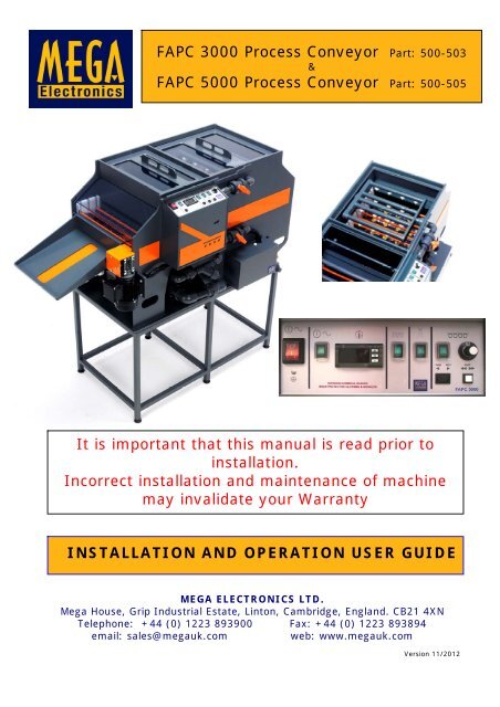
FAPC 3000 Process Conveyor Part: 500-503<br />
&<br />
FAPC 5000 Process Conveyor Part: 500-505<br />
It is important that this manual is read prior to<br />
installation.<br />
Incorrect installation and maintenance of machine<br />
may invalidate your Warranty<br />
INSTALLATION AND OPERATION USER GUIDE<br />
MEGA ELECTRONICS LTD.<br />
<strong>Mega</strong> House, Grip Industrial Estate, Linton, Cambridge, England. CB21 4XN<br />
Telephone: +44 (0) 1223 893900 Fax: +44 (0) 1223 893894<br />
email: sales@megauk.com<br />
web: www.megauk.com<br />
Version 11/2012
INDEX<br />
2<br />
PAGE<br />
1. Introduction 3/4<br />
2. Visual Inspection for transport damage 4<br />
3. Installation & Positioning 4<br />
4. Electrical Supply and Safety Notice 5/6<br />
5. Spray Wash Water Supply 6<br />
6. Spray Wash Drainage 6<br />
7. Process Chemical Drain 7<br />
8. Negative Pressure Port 7<br />
9. Mounting Stand (optional) 8<br />
10. Initial Start up 8 & 9<br />
11. Catch Tray 10<br />
12. Conveyor Speed Controller 10<br />
13. Temperature Control 10<br />
14. Protection System 11<br />
15. Removal of Control Panel Cover 12<br />
16. Removal of Clear Safety Cover 12<br />
17. Routine Maintenance 12 & 13<br />
18. FAPC Spares List 14<br />
19. Declaration of Conformity 15<br />
20. Processor wiring diagram 16
1. INTRODUCTION<br />
3<br />
The ‘Fanjet Adjustable Process Conveyor’ or FAPC Processors Unit is free standing<br />
and has been designed to work with the latest, developing, etching or stripping<br />
chemistry for the manufacture of prototypes, small batch work, Printed Circuits and<br />
Metal Components.<br />
We have designed our Processors with modern technology making them very easy<br />
machines to dismantle for routine cleaning and servicing.<br />
All controls and filters are easily accessible from front and sides, therefore<br />
eliminating the requirement to access the rear of the machine, and the necessity to<br />
move the machines once sited. The machines can be positioned with the back<br />
against a wall thus saving space.<br />
PLEASE NOTE:<br />
These machines are heavy.<br />
FAPC 3000 = 90 kilos<br />
FAPC 5000 = 150 kilos<br />
PLEASE READ THIS VERY IMPORTANT NOTICE<br />
The FAPC’s are constructed in PVC Plastic with welded seams and joints. This<br />
practice has been widely used throughout the Chemical Processing Industry for many<br />
years. It is physically very strong and extremely resistant to many corrosive<br />
chemicals. The only disadvantage with this technique is that it makes the<br />
construction hard and brittle.<br />
Therefore extreme care should be taken when placing the units on any surface.<br />
When removing from packaging, ensure the unit is lifted evenly and gently by the<br />
four lifting points, and placed very carefully on to a flat surface. Please avoid any<br />
heavy landings on corners, as this will induce a shear action which can cause<br />
cracking in the carcass.<br />
The unit has been designed for easy handling, manoeuvring and sighting.<br />
It incorporates 4 lifting points, which are clearly marked at each corner.<br />
This allows the machine to be lifted with either two people, by taking strong wooden or<br />
metal fixing struts and inserting them through the lifting points to allow easy lifting. Or<br />
alternatively by four people – one at each corner using the lifting handles.<br />
Fan Jet Nozzles are mounted in a rigid manifold system which can be adjusted to vary the<br />
impact angle of the sprays. Both top and bottom manifolds are identical, and can be easily<br />
removed as complete units for cleaning and maintenance.<br />
The pump is magnetically coupled which can handle liquids of 1.6 specific gravity (SG).<br />
Liquids of greater than 1.6 SG could damage the pump and invalidate the warranty.<br />
The unit incorporates 2 x 500W heaters which are located in the heater section of the<br />
specially developed baffled sump. This ensures even heating of liquid as it passes through<br />
this section.<br />
The baffled sump controls sediments and particles that may form and stops them<br />
from entering the flow systems and blocking filters and jets.
4<br />
The Process Lid incorporates a unique interlock system which shuts down the pump before<br />
the lid can be removed.<br />
The temperature is controlled by a digital controller that has a maximum limit of 50°C.<br />
There is also an over-temperature thermostat which cuts off power if the temperature of the<br />
liquids reaches 55°C, which could indicate a fault condition.<br />
The over-temperature device then has to be manually reset after investigation<br />
(see page 11)<br />
NB: Under no circumstances must the over-temperature device be tampered or modified,<br />
as this will invalidate the warranty.<br />
The Conveyor main-shaft is connected directly to a worm-drive gearbox and motor, which is<br />
controlled by a precision drive inverter. This ensures consistent and accurate feed speeds<br />
with sufficient torque, even down to speeds as low as 45mm per minute. This in turn<br />
eliminates the requirements for multi-passes of the board which can damage the dry film<br />
resist.<br />
2. VISUAL INSPECTION FOR TRANSPORT DAMAGE<br />
1) All our machines are built in-house in <strong>Mega</strong> and are fully tested before despatch. It is essential<br />
that upon delivery, the unit is thoroughly checked for damage that could occur in transit. Should any<br />
damage be found, please contact us immediately.<br />
Please keep all packaging – just in case the unit has to be returned for any reason.<br />
Replacement packaging would be chargeable.<br />
2) Remove lids and ensure all the conveyor rollers are in place, especially the top pinch rollers.<br />
Also make sure that the orange floating shields are resting in the small slots at the top of the roller<br />
holders, so that they rest just above the top pinch rollers on the entrance and exit points of the<br />
process chamber and the spray wash chamber.<br />
3) Remove the Filter Tray (see page 12 – figs: 19 & 20) and check that the two piece PVC base<br />
covering the liquid chamber has not moved. N.B. You will need a torch to check this. If by any<br />
chance they have moved, you will have to remove the top spray manifold (see page 13 – fig: 24) and<br />
then remove the centre transport rollers. You should now have access to the two base plates. After<br />
fixing in correct position, replace rollers and top spray manifold.<br />
WARNING:<br />
As with all electrically powered equipment, always isolate the electrical supply before<br />
removing any panels on these machines.<br />
The sump capacity for the FAPC 3000 is 35 litres of fluid and 50 litres for the FAPC 5000.<br />
The level of which is easily viewed through ‘Site-Glass’ at the front of the machine.<br />
3. INSTALLATION & POSITIONING<br />
Careful consideration for all necessary services should be reviewed before sighting this<br />
machine.<br />
For example: Size of Panels to be processed, Ample space must be available for loading and<br />
unloading panels.<br />
(Please bear in mind that as there are no controls at the back of the machine. It can be<br />
positioned against a wall).<br />
Ensure all water services are connected in accordance with local water bylaws. For effective<br />
washing of panels, we recommend a head pressure of 2 bar minimum closed valve with a<br />
supply flow 12 litres / minute.<br />
This equipment is Fluid Category 5 – Industrial and Chemical Plant
4. ELECTRICAL SUPPLY & SAFETY NOTICE<br />
5<br />
A mains Lead is supplied to connect the FAPC Unit to suitable electrical supply. The<br />
lead has a moulded into an IEC RFI Filter Socket (see figure 1) which plugs into the<br />
unit at the front, on the underside of the control module.<br />
The input socket is fused with a 13A 1” Ceramic fuse<br />
Figure 1<br />
MAINS LEAD<br />
Figure 2<br />
To keep the lead tidy and in place, route through the Lifting Aperture at the front on<br />
the left side (see figure 2).<br />
20 x 5mm Cartridge fuses are used throughout the unit for each process and are<br />
available as spares. Please refer to Page 15.<br />
The Mains Lead has a fused UK plug – fitted with 13A 1” Ceramic fuse.<br />
Replacement Fuses must be of the same value.<br />
DESCRIPTION FUSE <strong>FAPC3000</strong> <strong>FAPC5000</strong><br />
MAINS IN 13A 1” Ceramic 167321 167321<br />
HEATERS 5A 20 min F 167303 167303<br />
SPRAY PROCESS 5A 20 min T (<strong>FAPC3000</strong>)<br />
8A 20 min T (<strong>FAPC5000</strong>)<br />
167304<br />
167305<br />
SPRAY WASH 50 m A Slow Blow 20mm 167313 167313<br />
CONVEYOR 3.15A Slow Blow 20mm 167302 167302<br />
Please note that the mains fuse is located in the mains input IEC Socket.<br />
All other fuses are din rail mounted in the front panel control box and can be accessed by<br />
removing the two screws holding the control box cover on either side of the front of the box.<br />
This equipment is designed to safety class 1<br />
Before connecting this equipment to the mains electricity supply, examine the information on the<br />
apparatus rating label.<br />
Ensure that the mains supply is single phase alternating current (a.c.) of the stated frequency (Hz),<br />
with neutral nominally at earth potential.<br />
Check the supply voltage is within the stated range.<br />
The equipment rating label states the value of the fuse fitted to the apparatus itself. Ensure that the<br />
plug or supply circuit is fitted with an appropriate fuse of higher value.
WARNING THIS APPARATUS MUST BE EARTHED.<br />
The mains electrical supply should be connected via a ‘Residual Current Device’ (RCD) Available from<br />
<strong>Mega</strong> (part 161053) if required.<br />
Supply: - 220-240Vac 13 amps single phase / 50 Hz<br />
The wires in the mains lead are coloured in accordance with the following code:<br />
Green/Yellow - Earth (E)<br />
Blue<br />
- Neutral (N)<br />
Brown - Live (L)<br />
If a moulded fused plug is not fitted connect the wires to a non-reversible 3 pin plug as follows:-<br />
Green/Yellow wire to terminal marked:<br />
E (earth) or G (ground) or coloured Green or coloured Green/Yellow.<br />
Blue wire to terminal marked:<br />
N (neutral) or Common or coloured blue.<br />
Brown wire to terminal marked:<br />
L (live) or Phase or coloured Brown.<br />
NO SERVICING OR MAINTENANCE SHOULD BE CARRIED OUT UNTIL THE UNIT HAS BEEN SWITCHED<br />
OFF AND ISOLATED FROM THE MAINS ELECTRICITY SUPPLY.<br />
Any spare parts which may be required, are supplied on the understanding that the replacement of<br />
these requiring the exposure of live electrical connections will be undertaken by an electrically<br />
qualified person.<br />
5. SPRAY WASH WATER SUPPLY<br />
6<br />
Water is required for the Spray Wash Section. It may also be<br />
required if the unit is fitted with a cooling system (optional).<br />
Please refer to this section of the manual.<br />
Figure 3<br />
Wash Water requirement: 12 Litres / Minute.<br />
Minimum Pressure: 2 Bar (closed valve).<br />
Connection to the Water Supply is with the ‘Wash Machine’ type<br />
hose supplied ¾” BSP thread both ends. We recommend that the<br />
supply is terminated with a suitable isolator valve, which can be<br />
‘closed’ when the machine is not in use.<br />
Connection of the Supply Hose is on the left hand side<br />
(see figure 3).<br />
Ensure all water services are connected in accordance with local<br />
Water Bylaws.<br />
This equipment is fluid category 5 – Industrial and Chemicals<br />
Plant.<br />
6. SPRAY WASH DRAINAGE<br />
Figure 4<br />
The drain outlet is located on the left hand side of the unit<br />
next to the inlet (see figure 4).<br />
The Outlet pipe is 1¼” PVC. A 40mm compression bend<br />
is supplied for easy connection to waste or suitable<br />
effluent treatment plant.
7. PROCESS CHEMICAL DRAIN<br />
7<br />
To drain the Process Chamber, remove the threaded<br />
plug and fit the drain hose assembly (see figure 5)<br />
with the other end of the hose placed in a suitable<br />
container.<br />
Turn the drain valve clockwise 90 degrees to allow<br />
the chemistry to flow into the container.<br />
Careful consideration should be given to the<br />
capacity of the container and capacity of the<br />
sump to avoid over-filling and possible<br />
spillage.<br />
Figure 5<br />
When the bulk of the liquid has been drained in this way, it is necessary to leave the unit to<br />
drain further as liquid is controlled by a sediment<br />
baffle system, which will drain via a controlled<br />
bleeding system.<br />
Please allow for a further 7 litres for this process.<br />
This could take up to 30 minutes.<br />
As an added safety feature the valve is fitted with a<br />
threaded plug, should it be opened unintentionally<br />
(see figure 6).<br />
Figure 6<br />
This plug needs to be removed to fit the Drain Hose<br />
and replaced finger-tight before filling the unit.<br />
Do not over-tighten !<br />
IMPORTANT !<br />
Ensure this plug is in place before filling the Process Sump. Due to space required, this unit<br />
is shipped without the plug fitted.<br />
8. NEGATIVE PRESSURE PORT<br />
At the rear of the unit there is a provision for a hose connection, (see figure 7) whereby a<br />
Negative Pressure can be applied.<br />
Figure 7<br />
A Cap Is Fitted To This Part And<br />
Should Remain In Place If This<br />
Facility Is Not Used.<br />
NOTE: It is estimated that 90m³ / Hour is sufficient.<br />
A greater flow could risk drawing the chemistry out of the unit.<br />
CONNECTION: 1¼” PVC Pipe<br />
An Optional Kit is available.<br />
Items from this kit can be supplied separately.<br />
This Port draws air from the Neutral Chamber,<br />
which in turn keeps a Negative Pressure in the<br />
unit controlling the atomised chemistry when<br />
the panels enter the unit.<br />
If this port is used, it is important to note that<br />
only a gentle negative pressure is required to<br />
contain the chemistry.
8<br />
9. MOUNTING STAND (Optional)<br />
This stand has been designed to provide a<br />
stable platform for the unit and provide an<br />
optimum working height.<br />
It has six height adjustable feet, which<br />
should be used to find a level. This will<br />
help support the weight of the unit evenly.<br />
Figure 8<br />
More importantly, these feet can be<br />
adjusted to create a fall in the sump, so<br />
that when draining the chemistry it runs<br />
towards the Drain Valve on the Right Hand<br />
side of the front of the unit.<br />
(see figure 8 & 9).<br />
Use a Spirit Level and set at ‘Hard Bubble’<br />
to the Drain Valve Corner.<br />
Figure 9<br />
10. INITIAL START-UP<br />
After installation, it is necessary to ensure the<br />
unit functions correctly and that no transit<br />
damage has occurred.<br />
It is important that this procedure is followed<br />
carefully.<br />
1) Ensure that all switches on the Front Panel<br />
are in the position ‘OFF’<br />
(see figure 10)<br />
Also that the Wash Water Isolation valve is in the ‘Closed’ position.<br />
Figure 10<br />
2) Ensure that the Process Drain is in the ‘Closed’ position, and that the Drain Plug is<br />
in place. (see page 7 - figs: 5 & 6)<br />
Figure 11<br />
3) Unlock the lid by rotating the safety latch away<br />
from the top front body of the machine, thus<br />
activating the safety cut-out, which switches the<br />
pump off and enables the lid to be raised.<br />
NB. Do not try to lift the lid vertically, as this will<br />
damage the rear locking pieces.<br />
Just lift the lid 50 to 75mm (2”- 3”) at the front,<br />
pull it towards you and then lift if off.<br />
(see figure 11)
9<br />
4) Fill the sump from the top with water to the uppermost mark on the ‘Sight Glass’<br />
(see figure 12) Replace the lid and lock into place, by rotating the safety latch back into the<br />
locked position.<br />
5) Open the Wash Water Isolation Valve and check for leaks.<br />
Figure 12<br />
Sight<br />
glass<br />
6) Switch ‘ON’ the Mains Switch<br />
(IT WILL GLOW RED).<br />
7) Switch on the Heater Section indicated by the<br />
Temperature Symbol (IT WILL GLOW GREEN).<br />
The Digital display will flash ‘888’ for a few seconds,<br />
the liquid temperature will then be displayed. The<br />
‘Red Dot’ in the top left hand corner of the display<br />
indicates that the heaters are being energised.<br />
(refer to Page 11/ Section 12)<br />
8) Ensure that both Spray Jet manifold Valves are fully<br />
open (see figure 13).<br />
9) Switch on the spray Pump indicated with the 4 Spray<br />
Symbols. (Switch glows Green) The pump should be<br />
heard pumping.<br />
Liquid should be spraying from both top and bottom<br />
Spray Jets. There may be a few seconds delay as air in<br />
the pipe system will have to be purged out by the pump.<br />
Check for any leaks.<br />
Figure 13<br />
10) Switch ‘ON’ the Spray Wash indicated by the single spray symbol.<br />
(SWITCH GLOWS GREEN).<br />
Water should be spraying now from the top and bottom Spray Jets, allow for slight delay for<br />
the air in the pipe system. Check for leaks, including the Waste Water Drain.<br />
11) Finally Switch ‘ON’ the Conveyor (SWITCH GLOWS GREEN). The motor should now be<br />
turning the main drive shaft at the front of the Unit, which then drives all the rollers and<br />
Conveyor system.<br />
A high pitched noise may be heard from the motor, this is normal. Ensure the drive works<br />
across the entire range of 0 – 10 on the scale. With the knob set at 0 check the fast<br />
forward/reverse feature by pressing momentarily the square white button on the Control<br />
Panel. This should run the Conveyor at its maximum speed.<br />
PLEASE NOTE:<br />
The black rocker switch next to the square white button allows you to run the machine in<br />
forward or reverse mode, at pre-set speeds or maximum speed when white button is held<br />
down.<br />
Run the machine at maximum speed for 5 minutes in both directions and then switch<br />
conveyor OFF.<br />
Should any faults occur such as a leak for example, please contact your supplier<br />
immediately.<br />
Leave machine running for a further 2 hours with all functions on except spray wash. Set the<br />
conveyor to run at position 4 on the control knob.
10<br />
If at the end of this period if no leaks are visible and all functions are working<br />
satisfactorily switch off the unit, and drain water out as described on page 7. Your machine<br />
is now ready to be filled with the required process chemical.<br />
11 CATCH TRAY<br />
A catch tray is included (see figure 14). It is<br />
designed to collect panels as they exit the unit.<br />
Max. Panel length 12” (300mm).<br />
Holding capacity 1 kg maximum.<br />
The tray incorporates a claw feature which<br />
hooks over the exit just under the clear cover<br />
(see figure 15).<br />
Figure 13<br />
Figure 14<br />
Figure 15<br />
12. CONVEYOR SPEED CONTROLLER<br />
The Speed of the Drive Motor is controlled with a<br />
precision inverter. This is adjusted by a<br />
Potentiometer on the Front Panel.<br />
The Potentiometer has a ‘0-10’ Scale ‘0’ being<br />
the slowest speed.<br />
There is also a Digital Display on the Inverter<br />
which can be viewed through a window in the<br />
front of the Control Box Casing (see figure 16).<br />
Figure 16<br />
The Digital display rangers from 10-200 and can<br />
be referred to as 10% of the drive speed to<br />
200%.<br />
This added feature will be invaluable for setting<br />
up accurate parameters in some Processes.<br />
13. TEMPERATURE CONTROL<br />
The temperature of the chemistry is controlled by the Digital Controller on the Control Panel.<br />
The temperature is set at the factory to be 45°C, normal working temperature. However the<br />
temperature can be changed as follows: Press the P button and display will show SP. Press<br />
the up and down arrows to set the new temperature and then press the P button.<br />
PLEASE NOTE That the maximum temperature has been locked at 50°C to protect the unit<br />
from heat damage.
11<br />
14. PROTECTION SYSTEM<br />
OVER-TEMPERATURE CUT-OUT<br />
An over-temperature cut out is incorporated in the system as a back-up should there<br />
be a failure with the temperature control. It is pre-set to activate at 55°C. In the<br />
event All Power to the functions will be terminated and only Mains Switch will glow<br />
red.<br />
At this point the fault must be identified and rectified.<br />
The over-temperature cut-out has a normal reset which is housed within the heater<br />
junction box (see figure 12).<br />
The Reset Procedure is as follows:-<br />
1) Turn off the mains power (large red switch) and remove mains lead (figure 1).<br />
2) Remove the white plastic screw at the top heater junction box cover and gently<br />
draw the cover away from the unit at the top allowing it to hinge at the bottom.<br />
When the top part of the cover is clear of the chassis, move the cover<br />
downwards to unhook the lower part of the cover from the unit and the cover will<br />
then be free to remove.<br />
3) To the Left hand side of the cover chassis, there is a button (see figure 17) which can be<br />
depressed to reset – a Click should be heard and felt.<br />
NB: Before the switch can be reset the liquid will have to cool down to about 15°C.<br />
Figure 17<br />
4) Gently replace the cover, engaging<br />
the lower hinge section first.<br />
5) Replace the retaining screw and<br />
re-connect the electrical supply.<br />
Reset button<br />
LOW LIQUID LEVEL CUT-OUTS<br />
There are two liquid level sensors to protect the unit.<br />
One is to protect the pump from running dry and causing permanent damage.<br />
The second is to cut the power to the heaters and causing permanent damage. The display<br />
on the Temperature Controller will display ‘E1’ flashing.<br />
IMPORTANT<br />
Any attempt to override, modify or tamper with in any way will invalidate the Warranty.
15. REMOVAL OF CONTROL PANEL COVER<br />
12<br />
At the top front of each side of the control panel box, you will find 2 x black self tapping<br />
screws.<br />
When these are removed the front cover can be removed by tilting it slightly towards you<br />
and pulling upwards a few mm.<br />
16. REMOVAL OF CLEAR SAFETY COVER<br />
To remove the clear safety cover proceed as follows:<br />
Unscrew the stainless steel bolt below the control box.<br />
Figure 18<br />
Remove it fully, making sure you do not lose the<br />
plastic spacer fitted behind the cover.<br />
Holding the cover on the side left of the flow<br />
valves, carefully pull it towards you, so that it<br />
clears the orange handles of the flow control<br />
valves and then gently push the cover towards<br />
the right, so that it clicks off the two bends<br />
going into the top and bottom spray manifold<br />
To replace the cover, reverse this procedure.<br />
17. ROUTINE MAINTENANCE<br />
Each time you empty the tank to replace the chemistry – Firstly remove the Orange Plate<br />
then the Filter tray. (see figure 19 / 20)<br />
Figure 19 Ensure you have a tray or paper towels underneath to<br />
catch any drips.<br />
Figure 20<br />
Thoroughly wash the<br />
filter tray with water<br />
and replace, followed<br />
by the orange plate.<br />
Figure 21<br />
Inline filter<br />
Remove the in-line<br />
filter (figures 21 & 22)<br />
ensuring you have<br />
some paper towels or<br />
a cloth underneath it<br />
to catch any drips.<br />
Figure 22<br />
Then remove the filter locking ring and pull the filter<br />
out (see figure 23) of the filter housing. Thoroughly<br />
clean the filter inside and out. Reassembly the unit<br />
and screw back into its housing by hand (no tools needed).
Figure 23<br />
13<br />
FILTER<br />
FILTER LOCKING<br />
FILTER HOUSING<br />
When you have finished working for the day, always wipe down all surfaces with a clean<br />
damp cloth to prevent staining of the equipment, especially when using Ferric Chloride.<br />
Every six months, remove the spray bar manifolds. Then remove the spray nozzles and<br />
thoroughly clean from the front end with spray of water.<br />
(see figures 24,25 & 26)<br />
NB: If the machine is used on a daily basis for more than 3 to 4 hours, then change all the<br />
nozzles at this time. If only used intermittently, change the nozzles if you experience<br />
uneven etching after cleaning.<br />
Figure 24<br />
Undo this fitting to remove the spray bar<br />
manifold.<br />
Orange coloured Transport Rollers<br />
NB: to remove the bottom manifold, you need to lift out the transport rollers.<br />
(see figure 24).<br />
Figure 25 Figure 26<br />
Turn the nozzle anti-clockwise 90° (see figure 25) and remove (see figure 26)<br />
Replace nozzle using the reverse procedure, ensuring it is seated properly before<br />
twisting it into the locking position.<br />
NB: If by any chance any of the white nozzle holders move during this operation,<br />
carefully realign them after the nozzle has been locked into position.<br />
Do not try to mechanically clean the nozzle,<br />
as this could affect the nozzle pattern.
14<br />
18. FAPC 3000/ FAPC 5000 PROCESSORS SPARE PARTS<br />
PART<br />
DESCRIPTION<br />
Price each Price each<br />
NUMBER<br />
<strong>FAPC3000</strong> <strong>FAPC5000</strong><br />
160005 SOLENOID VALVE SINGLE 230V £8.90 £8.90<br />
160034 HEATER 240V 500W WITH NO THERMAL FUSE £37.95 £37.95<br />
160044 <strong>FAPC3000</strong> PUMP TE-7P-MD PP/VITON/CERAMIC 230V 50HZ £442.00 --------<br />
160048 <strong>FAPC5000</strong> SERFILCO ST6H MAC DRIVE PUMP ------ £810.00<br />
160142 MOTOR & WORM GEAR UNIT FOR PROCESS CONVEYOR £184.00 £184.00<br />
160052 OVER TEMPERATURE THERMOSTSAT RESETTABLE £7.50 £7.50<br />
191036 TEMPERATURE PROBE HOUSING IN PVC £5.00 £5.00<br />
163014 RELAY SPDT 10A 240V ac COIL £3.75 £3.75<br />
167160 SEE-SAW TYPE FLOAT SWITCH HORIZONTAL IN POLYPROP £9.95 £9.95<br />
164600 10K LIN COMMERCIAL POT £0.44 £0.44<br />
160088 ELMA KNOB BLACK 14.5mm WITH INDICATOR LINE £5.95 £5.95<br />
160089 ELMA KNOB CAP GREY £0.33 £0.33<br />
160086 NUMBER DIAL EMBOSSED £1.35 £1.35<br />
160080 STATOR FOR 14.5mm KNOB £1.50 £1.50<br />
160122 OMRON JX INVERTER DRIVE £137.60 £137.60<br />
160187 TEMPERATURE CONTROLLER £31.95 £31.95<br />
167129 SQUARE PUSH SWITCH WHITE £0.35 -----<br />
167130 LARGE RED ROCKER SWITCH £5.10 £5.10<br />
167150 MINI ROCKER SWITCH DPST GREEN ILLUM £3.00 £3.00<br />
167151 SPLASH PROOF COVER FOR 167150 £0.65 £0.65<br />
167302 20mm 3.15AF CERAMIC FUSE (DRIVE MOTOR) £0.21 £0.21<br />
167303 20mm 5A F CERAMIC FUSE (HEATER) £0.60 £0.60<br />
167304 20mm 5AT CERAMIC FUSE (PUMP) £0.29 -------<br />
167305 20mm 8AF CERAMIC FUSE (PUMP) <strong>FAPC5000</strong> ------- £0.31<br />
167312 FUSE 1A SLOWBLOW 20mmx5mm (DRIVE MOTOR) £0.15 £0.15<br />
167313 50Ma SLOWBLOW FUSE 20mmx5mm (SPRAY WASH) £0.15 £0.15<br />
167321 1” 13A MAINS CERAMIC FUSE £0.30 £0.30<br />
191077 GEAR SHAFT LOCKING COLLAR £2.24 £2.24<br />
191165-1 <strong>FAPC3000</strong> PLAIN PINCH ROLLER £32.76 -------<br />
191165-2 PINCH ROLLER WITH BLACK SPUR GEAR £37.44 -------<br />
191167-1 <strong>FAPC5000</strong> PLAIN PINCH ROLLER ------- £39.50<br />
191167-2 <strong>FAPC5000</strong> PINCHROLLER WITH BLACK SPUR-GEAR ------- £48.00<br />
250196 FAPC WORM GEARS BEIGE POLYPROP £5.00 £5.00<br />
250197 SPUR GEARS BLACK POLYETHYLENE £9.48 £9.48<br />
253100 FAPC BEARING DRIVE SHAFT BEARING £5.00 £5.00<br />
251301 SPRAY NOZZLE ADAPTOR PUSH FIT QUICK RELEASE £0.89 £0.89<br />
251300 SPRAY NOZZLE YELLOW FAN 902L 7DO QUICK RELEASE £1.68 £1.68<br />
MEGA ELECTRONICS LIMITED.<br />
MEGA HOUSE, GRIP INDUSTRIAL ESTATE, LINTON, CAMBRIDGE, CB21 4XN<br />
TEL: 01223 893900 FAX: 01223 893894 sales@megauk.com www.megauk.com
MEGA ELECTRONICS LIMITED.<br />
MEGA HOUSE, GRIP INDUSTRIAL ESTATE,<br />
LINTON, CAMBRIDGE, CB21 4XN<br />
TEL: 01223 893900 FAX: 01223 893894<br />
sales@megauk.com www.megauk.com<br />
15<br />
DECLARATION OF CONFORMITY<br />
We :<br />
<strong>Mega</strong> <strong>Electronics</strong> Ltd.<br />
<strong>Mega</strong> House<br />
Grip Industrial Estate<br />
Linton,<br />
CAMBRIDGE<br />
CB21 4XN<br />
Declare that the products:<br />
FAPC Process Conveyor Units.<br />
500-503<br />
500-505<br />
To which this declaration relates are to the best of our knowledge, in<br />
conformity<br />
with the following standards or other normative documents:<br />
EN 61000-6-3:2007<br />
EN 61000-6-1:2007<br />
EN 61000-3-2:2006<br />
Following the provisions of the EEC EMC Directive 2004/108/EC<br />
EN 61000-6-1 :2001<br />
EN 61000-6-3 :2001<br />
EN 61000-3-2 :1998<br />
Following provision of EEC LVD Directive 2006/95/EC<br />
Place of issue : CAMBRIDGE<br />
Date of issue : Thursday 22 nd March 2010<br />
M.A. Hall<br />
Technical Director<br />
<strong>Mega</strong> <strong>Electronics</strong> Limited.<br />
MEGA ELECTRONICS LTD.,<br />
Directors: M.F. Gebbie (MD) M.A. Hall (Technical), A.J. Hawkins (Sales), R.F. Stone (Production), J.P.R. Wells (Operations)<br />
Registered Office: <strong>Mega</strong> House, Grip Industrial Estate, Linton, Cambridge, CB21 4XN. Registered No: 1302367 England. VAT No: 215 1011 34
FAPC WIRING DIAGRAM<br />
16


