Picayune Strand Restoration Project Review Plan - Jacksonville ...
Picayune Strand Restoration Project Review Plan - Jacksonville ...
Picayune Strand Restoration Project Review Plan - Jacksonville ...

Create successful ePaper yourself
Turn your PDF publications into a flip-book with our unique Google optimized e-Paper software.
DEPARTMENT OF THE ARMY<br />
SOUTH ATLANTIC DIVISION, CORPS OF ENGINEERS <br />
ROOM 10M15, 60 FORSYTH ST., S.W. <br />
ATLANTA, GA 30303·8801 <br />
REPLY TO <br />
ATIENTION OF: <br />
CESAD-RBT 8 August 2011<br />
MEMORANDUM FOR COMMANDER, JACKSONVILLE DISTRJCT (CESAJ-EN-T/<br />
STEPHEN C. DUBA)<br />
SUBJECT: Approval ofthe <strong>Review</strong> <strong>Plan</strong> for <strong>Picayune</strong> <strong>Strand</strong> <strong>Restoration</strong> <strong>Project</strong>, Design and<br />
Construction Phases, Collier County, Florida<br />
1. References:<br />
a. Memorandum, CESAJ-EN-T, 26 April2011, Subject: Approval of the <strong>Review</strong> <strong>Plan</strong> for<br />
Picaylllle <strong>Strand</strong> <strong>Restoration</strong> <strong>Project</strong>, Design and Construction Phases, Collier County, Florida<br />
(Enclosure).<br />
b. EC 1165-2-209, Civil Works <strong>Review</strong> Policy, 31 January 2010.<br />
c. WRDA 2007 H. R. 1495 Public Law 110-114, 8 November 2007.<br />
2. The enclosed <strong>Review</strong> <strong>Plan</strong> for the <strong>Picayune</strong> <strong>Strand</strong> <strong>Restoration</strong> <strong>Project</strong>, Design and<br />
Construction Phases, Collier County, Florida dated 25 April 2011 submitted by reference l.a, has<br />
been reviewed by this office and is approved in accordance with reference l.b.<br />
3. The South Atlantic Division concurs v-lith the determination that a Type II Independent<br />
External Peer <strong>Review</strong> (IEPR) is not required on this project. The primary basis for the<br />
concurrence that a Type II IEPR is not required is the determination that no life safety concerns<br />
have been identified since the level of water associated with the project features will not create<br />
an adverse condition for life safety. Non-substantive changes to this RP do not require further<br />
approval.<br />
4. The District should take steps to post the <strong>Review</strong> <strong>Plan</strong> to its web site and provide a link to<br />
CESAD-RBT. Before posting to the web site, the names of Corps/ Army employees should be<br />
removed.
CESAD-RBT 8 August 2011<br />
SUBJECT: Approval ofthe <strong>Review</strong> <strong>Plan</strong> for <strong>Picayune</strong> <strong>Strand</strong> <strong>Restoration</strong> <strong>Project</strong>, Design and<br />
Construction Phases, Collier County, Florida<br />
5. The SAD point ofcontact is Mr. James Truelove, CESAD-RBT, 404-562-5121.<br />
FOR THE COMMANDER:<br />
Encl<br />
Chief, Business Technical Division<br />
2
DEPARTMENT OF THE ARMY<br />
JACKSONVILLE DISTRICT CORPS OF ENGINEERS <br />
P.O. BOX 4970 <br />
JACKSONVILLE, FLORIDA 32232-0019 <br />
REPLY TO <br />
A TTENT!ON OF <br />
CESAJ-EN-T 26 April 2011<br />
MEMORANDUM FOR Commander, South Atlantic Division (CESAD-RBT)<br />
SUBJECT: Approval of <strong>Review</strong> <strong>Plan</strong> for <strong>Picayune</strong> <strong>Strand</strong> <strong>Restoration</strong> <strong>Project</strong>, Design and<br />
Construction Phases, Collier County, Florida<br />
1. References.<br />
a. EC 1165-2-209, Civil Works <strong>Review</strong> Policy, 31 January 2010<br />
b. WRDA 2007 H. R. 1495 Public Law 110-114, 08 Nov 07<br />
2. I hereby request approval ofthe enclosed <strong>Review</strong> <strong>Plan</strong> and concurrence with the conclusion<br />
that Type II Independent External Peer <strong>Review</strong> (IEPR) of this project is not required. The Type<br />
II IEPR determination is based on the EC 1165-2-209 Risk Informed Decision Process as<br />
presented in the <strong>Review</strong> <strong>Plan</strong>. Approval ofthis plan is for the Design and Construction Phases.<br />
The <strong>Review</strong> <strong>Plan</strong> complies with applicable policy, provides Agency Technical <strong>Review</strong> and has<br />
been coordinated with the CESAD. It is my understanding that non-substantive changes to this<br />
<strong>Review</strong> <strong>Plan</strong>, should they become necessary, are authorized by CESAD.<br />
3. The district will post the CESAD approved <strong>Review</strong> <strong>Plan</strong> to its website and provide a link to<br />
the CESAD for its use. Names ofCorps/ Army employees are withheld from the posted version,<br />
in accordance with guidance.<br />
FOR THE COMMANDER:<br />
Encl<br />
STEPHEN C. DUBA, P.E.<br />
Chief, Engineering Division
REVIEW PLAN<br />
for<br />
PICAYUNE STRAND RESTORATION<br />
PROJECT<br />
DESIGN AND CONSTRUCTION PHASES<br />
COLLIER COUNTY, FLORIDA<br />
<strong>Jacksonville</strong> District<br />
April 25, 2011<br />
THE INFORMATION CONTAINED IN THIS REVIEW PLAN IS DISTRIBUTED SOLELY FOR<br />
THE PURPOSE OF PREDISSEMINATION PEER REVIEW UNDER APPLICABLE<br />
INFORMATION QUALITY GUIDELINES. IT HAS NOT BEEN FORMALLY DISSEMINATED BY<br />
THE U.S. ARMY CORPS OF ENGINEERS, JACKSONVILLE DISTRICT. IT DOES NOT<br />
REPRESENT AND SHOULD NOT BE CONSTRUED TO REPRESENT ANY AGENCY<br />
DETERMINATION OR POLICY.
Table of Contents<br />
2. PROJECT INFORMATION AND BACKGROUND ..................................................................... 3<br />
3. DISTRICT QUALITY CONTROL.............................................................................................. 14<br />
4. AGENCY TECHNICAL REVIEW.............................................................................................. 16<br />
5. INDEPENDENT EXTERNAL PEER REVIEW.......................................................................... 18<br />
6. MODEL CERTIFICATION AND APPROVAL ........................................................................... 20<br />
7. BUDGET AND SCHEDULE ..................................................................................................... 21<br />
8. POINTS OF CONTACT............................................................................................................ 23<br />
1
1. PURPOSE AND REQUIREMENTS<br />
a. Purpose. This <strong>Review</strong> <strong>Plan</strong> defines the scope and level of review activities for <strong>Picayune</strong><br />
<strong>Strand</strong> <strong>Restoration</strong> <strong>Project</strong> Design and Construction Phases. <strong>Review</strong> activities consist of District<br />
Quality Control (DQC), Construction Quality Management, Agency Technical <strong>Review</strong> (ATR), and<br />
Type II Independent External Peer <strong>Review</strong> (IEPR). Portions of the project are in the Pre-<br />
Construction, Engineering and Design (PED) Phase and the Construction Phase. The related<br />
documents are Implementation Documents that consist of <strong>Plan</strong>s and Specifications (P&S),<br />
Design Documentation Reports (DDR), and Engineering During Construction (EDC) products.<br />
Upon approval, this review plan will be included into the <strong>Project</strong> Management <strong>Plan</strong> as an<br />
appendix to the Quality Management <strong>Plan</strong>.<br />
b. References.<br />
(1) ER 1110-2-1150, Engineering and Design for Civil Works <strong>Project</strong>s, 31 Aug 1999<br />
(2) ER 1110-1-12, Engineering and Design Quality Management, 21 Jul 2006<br />
(3) ER 1180-1-6, Construction Quality Management, 30 Sep 1995<br />
(4) Enterprise Standard (ES)-08025, Government Construction Quality Assurance <strong>Plan</strong><br />
and <strong>Project</strong>/Contract Supplements<br />
(5) Enterprise Standard (ES)-08026, Three Phase Quality Control System<br />
(6) EC 1165-2-209, Civil Works <strong>Review</strong> Policy, 31 January 2010<br />
(7) Central and Southern Florida <strong>Project</strong>, <strong>Project</strong> Management <strong>Plan</strong>, <strong>Picayune</strong> <strong>Strand</strong><br />
<strong>Restoration</strong> <strong>Project</strong>, P2 Number 112375<br />
c. Requirements. This review plan was developed in accordance with EC 1165-2-209, which<br />
establishes an accountable, comprehensive, life-cycle review strategy for Civil Works products by<br />
providing a seamless process for review of all Civil Works projects from initial planning through<br />
design, construction, and Operation, Maintenance, Repair, Replacement and Rehabilitation<br />
(OMRR&R). The EC provides the procedures for ensuring the quality and credibility of U.S. Army<br />
Corps of Engineers (USACE) decision, implementation, and operations and maintenance<br />
documents and work products. The EC outlines three levels of review: District Quality Control,<br />
Agency Technical <strong>Review</strong>, and Independent External Peer <strong>Review</strong>.<br />
(1) District Quality Control (DQC). DQC is the review of basic science and engineering<br />
work products focused on fulfilling the project quality requirements defined in the <strong>Project</strong><br />
Management <strong>Plan</strong> (PMP). It is managed in the home district and may be conducted by<br />
staff in the home district as long as they are not doing the work involved in the study, or<br />
overseeing contracted work that is being reviewed. Basic quality control tools include a<br />
Quality Management <strong>Plan</strong> providing for seamless review, quality checks and reviews,<br />
supervisory reviews, <strong>Project</strong> Delivery Team (PDT) reviews, etc. Additionally, the PDT is<br />
responsible for a complete reading of the reports to assure the overall integrity of the<br />
reports, technical appendices and the recommendations before approval by the District<br />
Commander. The Major Subordinate Command (MSC)/District quality management plans<br />
address the conduct and documentation of this fundamental level of review.<br />
(2) Construction Quality Management (CQM). CQM methods and procedures are<br />
stipulated in above references. Obtaining quality construction is a combined<br />
responsibility of the construction contractor and the Government. The Construction<br />
element and Area/Resident Offices, as applicable, plan, coordinate, and manage the<br />
Construction Quality Management Program, plan and coordinate partnering of<br />
construction contracts, manage the Resident Management System (RMS), and monitor<br />
and evaluate CMR performance. Many of these tasks are accomplished using the RMS.<br />
In accordance with ER 1180-1-6, Construction Quality Management, Construction Branch<br />
and Area/Resident Office PDT members perform quality assurance of construction<br />
products.<br />
2
(3) Agency Technical <strong>Review</strong> (ATR). ATR is an in-depth review, managed within<br />
USACE, and conducted by a qualified team outside of the home district that is not<br />
involved in the day-to-day production of the project/product. The purpose of this review is<br />
to ensure the proper application of clearly established criteria, regulations, laws, codes,<br />
principles and professional practices. The ATR team reviews the various work products<br />
and assures that all the parts fit together in a coherent whole. ATR teams will be<br />
comprised of senior USACE personnel (Regional Technical Specialists (RTS), etc.), and<br />
may be supplemented by outside experts as appropriate. To assure independence, the<br />
leader of the ATR team shall be from outside the parent MSC.<br />
(4) Type II Independent External Peer <strong>Review</strong> (IEPR). IEPR is the most independent<br />
level of review, and is applied in cases that meet certain criteria where the risk and<br />
magnitude of the proposed project are such that a critical examination by a qualified team<br />
outside of USACE is warranted. In accordance with Section 2035 of Water Resources<br />
Development Act (WRDA) of 2007 and EC 1165-2-209, a Type II IEPR (SAR) shall be<br />
conducted on design and construction activities for hurricane and storm risk management<br />
and flood risk management projects, as well as other projects where existing and<br />
potential hazards pose a significant threat to human life prior to initiation of physical<br />
construction and periodically thereafter until construction activities are completed. IEPR<br />
should occur on a regular schedule sufficient to inform the Chief of Engineers on the<br />
adequacy, appropriateness, and acceptability of the design and construction activities for<br />
the purpose of assuring public health, safety, and welfare.<br />
d. <strong>Review</strong> Management Organization (RMO). The South Atlantic Division (SAD) is designated<br />
as the RMO for the <strong>Picayune</strong> <strong>Strand</strong> <strong>Restoration</strong> <strong>Project</strong> Design and Construction Phases. The<br />
RMO is responsible for managing the review activities described in this <strong>Review</strong> <strong>Plan</strong>. The RMO<br />
will also coordinate with the Cost Engineering Directory of Expertise (DX) as appropriate to<br />
ensure the appropriate expertise is included on the review teams to assess the adequacy of cost<br />
estimates, construction schedules and contingencies.<br />
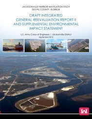
2. PROJECT INFORMATION AND BACKGROUND<br />
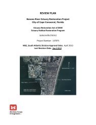
The <strong>Picayune</strong> <strong>Strand</strong> <strong>Restoration</strong> <strong>Project</strong> (PSRP), encompasses approximately 55,000 acres<br />
(241 km 2 or 23,995 ha) in Collier County, southwest Florida, between Interstate Highway 75 (I-75)<br />
and U.S. Highway 41.<br />
The PSRP (Formerly the Southern Golden Gate Estates <strong>Restoration</strong> <strong>Project</strong>) encompasses an<br />
area of sensitive environmental land located in southwestern Collier County, Florida. It is located<br />
southwest of the Florida Panther National Wildlife Refuge, north of the Ten Thousand Islands<br />
National Wildlife Refuge, east of the South Bell Meade State Conservation and Recreation Lands<br />
(CARL) project, west of the Fakahatchee <strong>Strand</strong> State Preserve, and northeast of Collier-<br />
Seminole State Park. The South Bell Meade Carl project, known simply as “Belle Meade”, and<br />
the <strong>Picayune</strong> <strong>Strand</strong> <strong>Restoration</strong> <strong>Project</strong> have been combined by the State of Florida to form the<br />
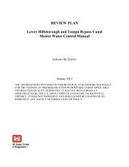
<strong>Picayune</strong> <strong>Strand</strong> State Forest, refer to Figure 1 – Regional <strong>Project</strong> Map.<br />
3
Southern Golden Gate Estates<br />
(SGGE) was planned as an<br />
extensive<br />
residential<br />
subdivision by Gulf American<br />
Corporation (GAC) beginning<br />
in the 1950’s. PSRP includes<br />
approximately 44 miles<br />
(77 km) of drainage canals and<br />
279 miles (449 km) of primary<br />
and secondary roads<br />
constructed in the 1960's as<br />
part of the former Southern<br />
Golden Gate Estates (SGGE)<br />
development The residential<br />
development failed before<br />
many of the planned houses<br />
were built. These roads and<br />
canals have over drained the<br />
area resulting in the reduction<br />
of aquifer recharge, increased<br />
freshwater shock load<br />
discharges to the receiving<br />
estuaries to the south, invasion<br />
by upland vegetation, loss of<br />
ecological connectivity and<br />
associated habitat, and<br />
increased frequency of forest<br />
fires. The <strong>Picayune</strong> <strong>Strand</strong><br />
<strong>Restoration</strong> <strong>Project</strong> (PSRP or<br />
<strong>Project</strong>) will restore 55,247<br />
acres of land to its pre- Figure 1 - Regional <strong>Project</strong> Map<br />
development condition.<br />
In 1985, when the State of Florida established the CARL project, land acquisition began for the<br />
PSRP. Today almost 98% of the 55,247 acres has been acquired in fee. The Water Resources<br />
Development Act of 1996 was enacted on October 12, 1996. Section 528 of the Act (Public Law<br />
104-303) entitled “Everglades and South Florida Ecosystem <strong>Restoration</strong>” authorized a number of<br />
ecosystem restoration activities and also provided specific direction and guidance for the<br />
Comprehensive Everglades <strong>Restoration</strong> <strong>Plan</strong> (CERP). In the Water Resources Development Act<br />
of 2000 (PL 106-541), Congress approved the Central and Southern Florida (C&SF) <strong>Project</strong><br />
Comprehensive <strong>Review</strong> Study Integrated Feasibility Report and Programmatic Environmental<br />
Impact Statement, which describes and outlines the CERP. Chapter 9, Section 9.1.9.1 Southern<br />
Golden Gate Estates <strong>Restoration</strong> (OPE) of the C&SF <strong>Project</strong> Comprehensive <strong>Review</strong> Study Book<br />
describes the features, improvements and purpose of the PSRP.<br />
The recommended plan for the PSRP is to remove the infrastructure of the subdivision and<br />
restore its pre-drainage hydrology and ecology, generating positive effects on the hydrology,<br />
vegetation and wildlife of the project area and surrounding public lands. The plan calls for the<br />
construction of a series of pump stations, tie-back levees, spreader berms and canal plugs to<br />
slow water flowing through existing canals and redistribute it across the landscape.<br />
Components of the project include the following:<br />
Installation of culverts under US-41 to the south<br />
Degrading of the existing roadways and filling of the side swales<br />
4
Plugging of the existing canals, including the Prairie, Merritt, Miller and Faka Union<br />
Canals<br />
Construction of three pump stations (Merritt, Faka Union, and Miller) to replace the<br />
conveyance of the respective canals<br />
Construction of Spreader berms and tie-back levees<br />
Construction of Protection Features which includes but is not limited to tie-back levees<br />
and berms.<br />
5
.....<br />
-<br />
.... ,. ...<br />
6
<strong>Project</strong> Status<br />
A <strong>Project</strong> Implementation Report (PIR) for the PSRP was completed by an AE Contractor<br />
(Parsons) in September 2004. In the PIR, alternatives for the design approach were discussed<br />
and an alternative (3D) was noted as the recommended plan. Due to the size of the project it<br />
was decided that it would be appropriate to break the design and construction of the individual<br />
features into separate projects. Since the initiation of the project, several components have been<br />
designed and construction has commenced on the first set of improvements known as the Merritt<br />
Pumping Station, Levees Canals and Roads (LCR).<br />
The PSRP project was implemented prior to the regulation (EC 1165-2-209: Water Resources<br />
Policies and Authorities, Civil Works <strong>Review</strong> Policy) which stipulates that a <strong>Project</strong> <strong>Review</strong> <strong>Plan</strong><br />
be implemented and therefore this project contains components that have already been design<br />
and/or construction initiated. The PSRP was originally managed by the Sponsor of the project,<br />
South Florida Water Management District (SFWMD), who performed or caused to be performed,<br />
the PIR, Hydraulic and Hydrologic modeling, as well as design efforts and construction plans and<br />
specifications through the Acceler8 program. The SFWMD implemented review activities for<br />
compliance with USACE guidance ER 1110-1-12 current edition at the time of product<br />
preparation. In 2008, at the request of SFWMD, the USACE assumed the lead as the managing<br />
entity.<br />
Table 1 on the following page lists the review history of the PSRP overall project and components<br />
of the PSRP.<br />
TABLE 1 – REVIEW HISTORY<br />
No. <strong>Review</strong> Duration<br />
1 <strong>Project</strong>'s Team Jan 05 - Jan -5<br />
2 BODR SOW Feb 05 - Mar 05<br />
3 Prairie Canal (Intermediate <strong>Plan</strong>s & Specs. May 05 - May 05<br />
4 H&H Modeling SOW Jun 05 - Jun 05<br />
5 Basis of Design <strong>Review</strong> (BODR) - Pump Station Jun 05 - Jul 05<br />
6 H&H Modeling QA/QC Technical Memo Jul 05 - Jul 05<br />
7 Pump Station Preliminary Design SOW Jul 05 - Jul 05<br />
8 BODR SOW - Protection Levees Aug 05 - Aug 05<br />
9 H&H Modeling SOW Phase1 Aug 05 - Aug 05<br />
10 H&H Modeling SOW Phase2 Nov 05 - Nov 05<br />
11 Geotech/Survey SOW for Levees, Canals & Roads Dec 05 - Jan 06<br />
12 Manatee Impact Study SOW Jan 06 - Jan 06<br />
13 Protection Levees Updated SOW Jan 06 - Jan 06<br />
14 Survey Deliverables - Pump Stations Jan 06 - Jan 06<br />
15 Pump Stations Preliminary Design Feb 06 - Feb -06<br />
16 Prairie Canal - 90% <strong>Plan</strong>s & Specifications Feb 06 - Mar 06<br />
17 H&H Phase 1 Model Analysis Report Mar 06 - Mar 06<br />
18 Road Removal SOW Mar 06 - Mar 06<br />
19 Pump Stations Preliminary Design Resubmittal Apr 06 - Apr 06<br />
20 Draft Operations Manual May 06 - May 06<br />
21 Prairie Canal Design Analysis (USACE) May 06 - May 06<br />
22 Road Removal Pre-Final P&S Jun 06 - Jun 06<br />
23 H&H Phase II TM: Model Calibration Jun 06 - Jun 06<br />
24 Levees Canals & Roadw ays Preliminary Design SOW Jul 06 - Jul 06<br />
25 LCR BODR TM: Interior Drainage Analysis Jul 06 - Jul 06<br />
26 H&H Phase II TM: Modeling Draft Jul 06 - Jul 06<br />
7
TABLE 1 CONTINUED<br />
No. <strong>Review</strong> Duration<br />
27 Draft BODR Levees, Canals and Roads Jul 06 - Aug 06<br />
28 Opinion of Probable Construction Costs Aug 06 - Aug 06<br />
29 Intermediate Design - Pump Stations Aug 06 - Sep 06<br />
30 H&H Phase II, TM: Hw y 41 Road bed Analysis Aug 06 - Sep 06<br />
31 H&H Phase II, TM: Modeling Draft - IMC Sep 06 - Sep 06<br />
32 Survey Report Oct 06 - Oct 06<br />
33 H&H Modeling Final Draft Report Mar 07 - Apr 07<br />
34 Geotech - Spreader Berms Technical Memorandum Nov 07 - Nov 07<br />
35 Private Lands Canal Extension Geotechnical Report Dec 07 - Dec 07<br />
36 Geotech - Tieback Levee Technical Memorandum Dec 07 - Dec 08<br />
37 Faka Union Pump Station Pre-Final (90%) Design Jan 08 - Feb 08<br />
38 Miller Pump Station Pre-Final (90%) Design Jan 08 - Feb 08<br />
39 Draft Geotechnical Report - Site Survey LCR Feb 08 - Feb 08<br />
40 Merritt Pump Station - Pump Model Test Procedure Feb 10 - Feb 10<br />
41 EDC1 - Merritt Pump Station Jul 10 - Jul 10<br />
42 EDC2 - Merritt Pump Station Jul 10 - Jul 10<br />
43 EDC3 (WM012) Merritt Pump Station Aug 10 - Aug 10<br />
44 EDC4 (WM016) Merritt Pump Station Sep 10 - Sep 10<br />
45 EDC5 (WM019) Vegetation Clearing Oct 10 - Oct 10<br />
46 EDC6 (WM 017) Road Removal Nov 10 - Nov 10<br />
47 Hydrologic & Hydraulic Scope of Work Nov 10 - Nov 10<br />
48 EDC7 (WM021) Riprap, Bedding Material, and Geotextile Dec 10 - Jan 11<br />
49 EDC8 (WM022) Overhead Bridge Crane Dec 10 - Jan 11<br />
50 Topographic and Boundary Survey (POI) Dec 10 - Jan 11<br />
51 Miller Geotechnical Investigation SOW (Draft) Jan 11 - Jan 11<br />
It was identified that the plans and specifications prepared under the management of SFWMD did<br />
not meet the criteria established for projects lead by the USACE. Subsequently, the Designs for<br />
the Merritt, Faka Union and Miller Pumping Station <strong>Plan</strong>s have been or will need to be updated.<br />
To date, the Merritt and Faka Union <strong>Plan</strong>s and specifications have been updated and the update<br />
to Miller will begin in February 2011.<br />
Table 2 below lists a summary of the tasks and construction activities previously initiated and<br />
their associated status or anticipated commencement and completion dates.<br />
8
TABLE 2: DESIGN/CONSTRUCTION ACTIVITIES – COMPLETED OR UNDERWAY<br />
Reports Date Issued Contractor<br />
<strong>Project</strong> Implementation Report (PIR) Sep-04 Parsons<br />
Basis of Design Report (BODR) Aug-06 Parsons<br />
Construction <strong>Plan</strong>s Begin End<br />
Protection Features<br />
Port of the Islands Jan-11 Oct-12<br />
Private Lands Dec-11 Nov-13<br />
6Ls Farm Jan-12 Apr-14<br />
Miller Pumping Station Jan-11 Jul-12<br />
Construction Const. Comm. Contractor<br />
Merritt Pumping Station Jan-10 Harry Pepper<br />
Table 3 lists a summary of the Design / Construction activities to be completed for the remainder<br />
of the PSRP.<br />
TABLE 3: DESIGN/CONSTRUCTION ACTIVITIES TO BE PERFORMED<br />
<strong>Plan</strong>s and Specifications Begin End<br />
Protection Features<br />
Port of the Islands Jan-11 Oct-12<br />
Private Lands Dec-11 Nov-13<br />
6Ls Farm Jan-12 Apr-14<br />
Miller Pumping Station Jan-11 Jul-12<br />
Construction Begin End<br />
Faka Union Pumping Station Jan-11 Dec-13<br />
Protection Features<br />
Port of the Islands Jan-13 Oct-13<br />
Private Lands Dec-13 Oct-14<br />
6Ls Farm Jan-12 Apr-14<br />
Miller Pumping Station Jul-14 Sep-15<br />
Prairie Canal Phase<br />
Canal Plugs<br />
Plugging of the Prairie Canal consists of earthen plugs, which are located approximately 1,300<br />
feet apart, begin at approximately 80 th Street west of the sourthernmost existing plug and<br />
continues south to 118 th Street. Plugs may not exist at every location depending on fill<br />
availability; however, all spoil material along the canals within the project limits will be returned to<br />
the canal.<br />
Road Removal<br />
Stewart Blvd. from Patterson Blvd to the Prairie Canal and Janes Senic Drive from the Prairie<br />
Canal east approximately 3,000 feet are to have the asphalt removed and culverts added to allow<br />
for sheet flow to the southern portion of the <strong>Picayune</strong> <strong>Strand</strong>. The existing berms to the north and<br />
south of the roads are to be degraded.<br />
9
Merritt Phase<br />
Pump Station<br />
This feature will pump water from the Merritt Canal into a spreader basin for release to the<br />
downstream restoration area. The S-488 pump station is comprised of two (2) 75 cfs electrical<br />
pumps and four (4) 220 cfs diesel pumps for a total capacity of 1,030 cfs; however, the maximum<br />
design flow for flood protection is 880 cfs using the four high flow pumps.<br />
Tie-Back Levee<br />
The tie-back levee with a 14-foot wide access road is located along the northern extent of the<br />
restoration area and is intended to prohibit flow to the north during pump operations. The eastern<br />
tie-back levee is approximately 11,760 lineal feet extending from the pump station site eastward<br />
to Basil Road, which is adjacent to the Prairie Canal area. The western tie-back levee is primarily<br />
a north-south levee located adjacent to existing roadways, Merritt Boulevard and 66 th Avenue SE.<br />
This levee, which is approximately 11,030 feet in length, begins at the pump station site and ends<br />
th<br />
west of Merritt Boulevard on 66 Avenue SE. The levee elevation varies from 14.0 to 15.0 ft<br />
NAVD with the highest section near the pump station site.<br />
Spreader Berm/Basin and Weirs<br />
Approximately 3,500 lineal feet of spreader berm oriented in an east-west direction connects to<br />
the tie-back levees on either side of the pump station site to create a spreader basin. The pump<br />
station discharges into this spreader basin, which fills and overflows into the restoration area via<br />
multiple concrete weirs with varying widths and elevations. Overflow weirs S-488A and S-488B<br />
are at elevation 10.0-ft. NAVD with a width of 150 feet; secondary weirs S-488C, S-488D and S-<br />
488F through S-488I are all 45 feet wide at elevation 9.5 ft. NAVD; and the primary weir, S-$88E,<br />
is 65 feet wide with an elevation of 9.0 ft. NAVD. A distribution canal located on the interior of the<br />
spreader basin improves the distribution of flow while providing material for the berm<br />
construction.<br />
Road Removal<br />
All remaining asphalt roads south of I-75 between the Prairie Canal and the Faka Union Canal,<br />
with the exception of the primary access roads, will be degraded to natural grade. Primary access<br />
roads within the restoration area will still require removal of the asphalt material and clearing of<br />
vegetation. Culverts will be installed at 11 locations under Stewart Boulevard from Patterson<br />
Boulevard west to the Faka Union Canal to allow sheet flow to continue south.<br />
Canal Plugs<br />
Earthen canal plugs, with a minimum length 100 feet per plug, are located within the Merritt Canal<br />
and the south section of the Prairie Canal at the intersection of the roads with the canals. The<br />
existing spoil material along the top of bank on either side of the Merritt and Prairie Canals is the<br />
primary source of material for the canal plugs. The Merritt Canal plugs begin at 56 th Avenue SE<br />
and continue south to 134 th Avenue South with additional plugs in the east-west section of the<br />
Merritt Canal east of the Faka Union Canal. Additionally, an existing farm ditch located between<br />
the Merritt Canal and the Prairie Canal will be completely backfilled to natural grade.<br />
Faka Union Phase<br />
Pump Station<br />
The S-487 pump station is comprised of three (3) 100 cfs electrical pumps and five (5) 470 cfs<br />
diesel pumps for a total capacity of 2,650 cfs, however, the maximum design flow for flood<br />
protection is 2,350 cfs using the five high flow pumps.<br />
Tie-Back Levee<br />
The tie-back levee with a 14-foot wide access road is located along the northern extent of the<br />
restoration area and is intended to prohibit flow to the north during pump operations. The eastern<br />
tie-back levee is approximately 5,680 lineal feet extending from the pump station site to the west<br />
10
end of the Merritt tie-back levee along the south side of 66 th Avenue SE. The western tie-back<br />
levee, which is approximately 10,600 lineal feet, is primarily located along the south side of 66th<br />
Avenue SE until Everglades Boulevard where it jogs north to the south side of 64 th Avenue SE,<br />
then continues east to the Miller Canal Pump Station site. The levee elevation varies from 15.3 to<br />
16.0 ft. NAVD with the highest section near the pump station site.<br />
Spreader Berm/Basin and Weirs<br />
Approximately 9,290 lineal feet of spreader berm oriented in an east-west direction connects to<br />
the tie-back levees on either side of the pump station site to create a spreader basin. The pump<br />
station discharges into this spreader basin, which fills and overflows into the restoration area via<br />
multiple concrete weirs with varying widths and elevations. All of the weirs are 80 feet wide at<br />
elevation 9.5 ft. NAVD with the exception of the following: the overflow weirs, S-487F, D-487G, S-<br />
487N and S-487R, are at elevation 10.0 ft. NAVD with a width of 110 feet and the S-487H weir is<br />
45 feet wide with an elevation of 10.0Ft. NAVD. A distribution canal located on the interior of the<br />
spreader basin improves the distribution of flow while providing material for the berm<br />
construction.<br />
Road Removal<br />
All remaining asphalt roads in the Faka Union Construction limits south of I-75 between the Faka<br />
Union Canal and Miller Canal, with the exception of the primary access roads, will be degraded to<br />
natural grade. Primary access roads within the restoration area will still require removal of the<br />
asphalt material and clearing of vegetation.<br />
Protection Features<br />
The protection features portion of the project deals with the water resource engineering needed to<br />
determine what protection features will be needed in the surrounding project areas. There will be<br />
three phases for this work. The first phase will evaluate the best available data that was<br />
developed by the Corps and SFWMD during the PIR and ACCELER8 design phases of the<br />
<strong>Picayune</strong> <strong>Strand</strong> <strong>Project</strong>. The second phase will involve developing hydrologic and hydraulic<br />
computer models for the analysis and design of the protection features. The final phase will be a<br />
detailed design phase and involve developing the best plan to construct each of the necessary<br />
project features to meet the project’s goal. During this phase design will provide sufficient detail<br />
to document design decisions and produce detailed guidance for developing construction plans<br />
and specification for the <strong>Picayune</strong> <strong>Strand</strong> <strong>Restoration</strong> <strong>Project</strong>.<br />
The anticipated features include the following:<br />
1) A berm along the east side of Port of the Islands approximately 3’ in height and 8’ wide at<br />
the top.<br />
11
2) An extension of the tie-back levee located west of the Miller Pump Station. The levee<br />
would vary in height (approximately xx)_with a 15’ wide driveable surface at the top.<br />
3) A berm/levee around a portion of the 6L’s farm located to the southwest of the project,<br />
north of US 41. H&H Modeling is required to provide a more definitive scope and design<br />
of the levee.<br />
Miller Phase<br />
Pump Station<br />
This feature will pump water from the Miller Canal into a spreader basin for release to the<br />
downstream restoration area. The Miller pump station is comprised of two (2) 75 cfs electrical<br />
pumps and six (6) 220 cfs diesel pumps for a total capacity of 1,470 cfs; however, the maximum<br />
design flow for flood protection is 1,350 cfs using the six high flow pumps.<br />
Tie-Back Levee<br />
The tie-back levee with a 14-foot wide access road is located along the northern extent of the<br />
restoration area and is intended to prohibit flow to the north during pump operations. The eastern<br />
tie-back levee is being designed and constructed under the Faka Union Pump Station scope of<br />
work. The western tie-back levee is primarily an east-west levee located adjacent to existing<br />
roadway, 64 th Avenue SE, also has a small portion that extends to the north just past the private<br />
12
lands. This levee, which is approximately 10,000 feet in length, begins at the pump station site<br />
and ends west of the private lands. The levee elevation varies from approximately 14.5 to 15.5 ft<br />
NAVD with the highest section near the pump station site.<br />
Spreader Berm/Basin and Weirs<br />
Approximately 7,100 lineal feet of spreader berm oriented in an east-west direction connects to<br />
the tie-back levees on either side of the pump station site to create a spreader basin. The pump<br />
station discharges into this spreader basin, which fills and overflows into the restoration area via<br />
multiple concrete weirs with varying widths and elevations. Primary weir W-5 is at an elevation of<br />
9.0 NAVD with a width of 45’. Overflow weirs W-1 and W-4 are at elevation 10.0-ft. NAVD with a<br />
width of 100 feet; secondary weirs W-3, W-6, W-7, W-8 and W-9 are at elevation 9.5 with a width<br />
of 90, secondary weir W-2 is at elevation 9.5 with a width of 100’. A distribution canal located on<br />
the interior of the spreader basin improves the distribution of flow while providing material for the<br />
berm construction.<br />
Road Removal<br />
All remaining asphalt roads south of I-75 between the Faka Union Canal and the Miller Canal,<br />
with the exception of the primary access roads, will be degraded to natural grade. Primary access<br />
roads within the restoration area will still require removal of the asphalt material and clearing of<br />
vegetation. Culverts will be installed at locations under Miller Boulevard to allow sheet flow to<br />
continue west.<br />
Canal Plugs<br />
Earthen canal plugs, with a minimum length 100 feet per plug, are located within the Miller Canal.<br />
The existing spoil material along the top of bank on either side of the Miller Canal is the primary<br />
source of material for the canal plugs. The Miller Canal plugs begin at the Miller Pump Station<br />
and continue south to 128 th Avenue South (aka Lynch Blvd.) with additional plugs in the east-west<br />
section of the Miller Canal west of the Faka Union Canal. Plugs may not exist at every location<br />
depending on fill availability; however, all spoil material along the canals within the project limits<br />
will be returned to the canal.<br />
13
3. DISTRICT QUALITY CONTROL<br />
a. In-house Prepared Products. District Quality Control Quality Control and Quality Assurance<br />
activities for implementation documents (DDRs and P&S) are stipulated in ER 1110-1-12,<br />
Engineering & Design Quality Management. Agency Technical <strong>Review</strong> (formerly called<br />
Independent Technical <strong>Review</strong>), quality checks and reviews, supervisory reviews, <strong>Project</strong><br />
Delivery Team (PDT) reviews are required by the ER and those items are embodied into the<br />
CESAJ EN Procedures Portal which can be viewed at the following hyperlink. The subject project<br />
is prepared by the <strong>Jacksonville</strong> District and by others including Architect-Engineer Firms and<br />
other Corps of Engineers Offices. The related procedures for in-house products are located at<br />
the following hyperlink. A related screen shot is below.<br />
https://intranet.saj.usace.army.mil/~rwp/QCForProducts.htm<br />
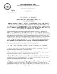
b. Products Prepared by Others. The related SAJ procedures for Products Prepared by Others<br />
are located at the below site. Screen shots are also provided below.<br />
https://intranet.saj.usace.army.mil/~rwp/branch_procedures.htm<br />
14
0~ • 1 c..w..:w~$111~·'""'...........tQC~'-""=. '""'""'======-='-'·'-'A"~ 't A I· f_p .-<br />
t.'o tl!'t b!~ mER 1110.1·12 P•to W llflii•IIY customeff'l'(lllsut<br />
~pec:lc II!QUI!emf•rdoo<br />
Tht OA CtrtiitltiM will COI\Sl$1 ed ~lltl obo-.o. coti\Pift«t Oil. Follfl llttnotD!od 011. com,.nl'$ complfC.o QA<br />
Cl!..:khsl, tOIIIpiO':od -"9potd01 £ ITR bms and anncu!lld ITR COIIUlWflU Th6 QA Cllllik: ~bOII .along -.ell<br />
SUIIFOIIlllg llocumtl!latloll ..,r bot ikd .U. tilt prqoe1 ~,.<br />
15
c. Engineering and Design during Construction Phase DQC/QA. Engineering effort during<br />
construction includes completion of Design Documentation Reports (DDR’s), modification of P&S<br />
(where appropriate), and preparation of engineering considerations and instructions to field<br />
personnel. Additional effort is needed to review selected contractor submittals, conduct site visits,<br />
and prepare construction foundation reports and concrete reports. The engineers must also<br />
provide support for contract claims and modifications, development of operation and maintenance<br />
(O&M or OMRR&R) manuals, emergency action plans (including inundation maps), and review of<br />
as-built drawings.<br />
d. Construction Quality Management. Construction Division (CD) efforts in support of the<br />
<strong>Picayune</strong> <strong>Strand</strong> <strong>Restoration</strong> <strong>Project</strong> started during the design process by actively participating in<br />
the PDT during the early stages of design and will continue until completion of the project. CD<br />
played an important role during the BCOE review process and coordination of all independent<br />
review team comments. During construction, Division Quality Assurance personnel, provides<br />
training and support to contractor personnel on QCS issues, provides Construction Quality<br />
Management training to all Contractor personnel engaged in Quality control and office<br />
engineering functions and serves as primary points of contracts for technical and quality<br />
control/assurance issues. CD also develops the scope of work and coordinates the issuance of<br />
task orders for obtaining material testing services and quality assurance for services contracts.<br />
4. AGENCY TECHNICAL REVIEW<br />
a. General. Agency Technical <strong>Review</strong> (ATR) is undertaken to "ensure the quality and credibility<br />
of the government's scientific information" in accordance with EC 1165-2-209 and ER 1110-1-12.<br />
An ATR will be performed on the P&S and DDR intermediate and pre-final submittals.<br />
ATR comments are documented in the DrChecks sm model review documentation database.<br />
sm<br />
sm<br />
DrChecks is a module in the ProjNet suite of tools developed and operated at ERDC-CERL<br />
(www.projnet.org).<br />
ATR is being conducted by individuals and organizations that are external to the <strong>Jacksonville</strong><br />
District. SAD will be the RMO that will manage the ATR. The required disciplines and<br />
experience are described below.<br />
b. PDT Discipline Descriptions. The ATR team composition will mirror the following PDT<br />
expertise used to prepare project work products.<br />
H&H Analysis:<br />
Hydraulic / Hydrologic Engineer<br />
Civil Engineer<br />
Geotechnical Engineer<br />
Protection Features (Port of the Islands, Private Lands and 6Ls):<br />
Hydraulic / Hydrologic Engineer<br />
Civil Engineer<br />
Geotechnical Engineer<br />
Geologist<br />
Geomatics<br />
Cost Engineer<br />
Real Estate Specialist<br />
ETHRW/Chemist<br />
Archeologist<br />
Environmental Scientist/Biologist<br />
Environmental Engineer<br />
16
Miller Pump Station:<br />
Civil Engineer<br />
Hydraulic / Hydrologic Engineer<br />
Structural Engineer<br />
Mechanical Engineer<br />
Electrical Engineer<br />
Geotechnical Engineer<br />
Geologist<br />
Cost Engineering<br />
Real Estate Specialist<br />
ETHRW/Chemist<br />
Land Surveyor<br />
Archeologist<br />
Environmental Scientist/Biologist<br />
Environmental Engineer<br />
c. ATR Disciplines. As stipulated ER 1110-1-12, ATR members were sought from the following<br />
sources: regional technical specialists (RTS); appointed subject matter experts (SME) from other<br />
districts; senior level experts from other districts; Center of Expertise staff; appointed SME or<br />
senior level experts from the responsible district; experts from other USACE commands;<br />
contractors; academic or other technical experts; or a combination of the above. The ATR Team<br />
is comprised of the following disciplines; knowledge, skills and abilities; and experience levels.<br />
Hydrology and Hydraulics. Two to three team members will be required to review the hydraulic<br />
design, hydraulic modeling, hydrologic modeling, and wind/wave analyses. The team member(s)<br />
should be registered professionals with 10 or more years experience in conducting and<br />
evaluating hydrologic and hydraulic analyses for flood risk management projects. Experience<br />
with 2D hydraulic modeling, 3D hydrologic and groundwater modeling, wind/wave analysis, and<br />
performance of risk assessments is required.<br />
Geotechnical Engineering. The team member should be a registered professional engineer and<br />
have 10 or more years experience in geotechnical engineering. Experience needs to include<br />
geotechnical evaluation of flood risk management structures. Experience needs to encompass<br />
static and dynamic slope stability evaluation; evaluation of the seepage through earthen<br />
embankments and under seepage through the foundation of the flood risk management<br />
structures, including dams, levee embankments, floodwalls, closure structures and other pertinent<br />
features; and settlement evaluations.<br />
Structural Engineering. The team member should be a registered professional engineer and<br />
have 10 or more years experience in structural engineering. Experience needs to include the<br />
engineering and design of flood risk management project features such as pump stations,<br />
conveyance culverts, and spillways.<br />
Mechanical and Electrical Engineering. The team members should have 10 or more years<br />
experience in mechanical and electrical engineering. Experience needs to include engineering<br />
and design of flood risk management project features such as pump stations, related systems<br />
and components.<br />
Civil Engineering. The team member should be a registered professional engineer and have 10<br />
or more years experience with civil/site work projects to include embankments, roads and<br />
highways, relocations, paving and drainage.<br />
Cost Engineering. The team member should have 10 or more years demonstrated in the<br />
preparation of cost estimates, cost risk analyses and cost engineering. Experience is needed for<br />
complex Civil Works projects to include dams and impoundments.<br />
17
Environmental Scientist/Biologist/NEPA Compliance. The team member should have 10 or more<br />
years of experience in NEPA compliance and preparing and coordinating EA’s and EIS’s on<br />
District projects, including preparation of the environmental portions of project reports. Team<br />
member should also be able to execute and evaluate compliance with environmental law such as<br />
the Endangered Species Act, Coastal Zone Management Act, Migratory Bird Treaty Act, and<br />
Marine Mammal Protection Act.<br />
Environmental Engineer. The team member should be an environmental engineer and have 7 or<br />
more years experience with water resource and or restoration projects. The member should have<br />
extensive experience with nutrient loading/TP concerns within the state of Florida. The team<br />
member should be familiar with the state water quality criteria for the project area.<br />
Geomatics & Survey. The team member must be a Professional Surveyor and Mapper (PSM)<br />
licensed in the State of Florida and have a minimum of 10 years experience with Topographic,<br />
Bathymetric, and Construction Layout surveys.<br />
EHTRW/Chemist. The team member should be a chemist with 10 or more years experience in<br />
conducting and evaluating ecological risk assessments.<br />
Geologist. The team member should be a registered professional geologist and should have at<br />
least 10 years of specialized experience in but not limited to; knowledge of geological theories,<br />
principles, and methodology, have the ability to plan, direct, and report conclusions of geologic<br />
investigations. The individual should also be skilled in interpretation of field test data for<br />
determining the foundation strengths engineering purposes. The team member should also serve<br />
as the Engineering Geologist, utilizing a highly developed professional knowledge of geological<br />
theories and applications for complex assignments of considerable breadth and scope related to<br />
engineering geologic and hydrogeologic investigations. His/her experience should include<br />
planning, directing, analyzing and reporting conclusions of geologic and coastal investigations<br />
pertaining to the design and construction of Civil Works Resources <strong>Project</strong>s throughout the State<br />
of Florida, and must have a strong background in Florida Geology in general to be able to provide<br />
technical guidance to other Geologists and Engineers not only in the preparation of project<br />
reports, but also to resolve geologic problems involved.<br />
Archeologist. The team member should be a professional archeologist preferably with an<br />
advanced degree and with at least 10 years experience doing federal cultural resource<br />
management.<br />
Real Estate Specialists. The Real Estate Specialist should be a senior level employee with<br />
demonstrated project Pre-Construction, Engineering and Design Phase experience.<br />
ATR Team Leader. The ATR Team Leader should have 10 or more years experience with Civil<br />
Works <strong>Project</strong>s and have performed ATR Team Leader duties on complex civil works projects.<br />
ATR Team Leader can also serve as one of the review disciplines.<br />
e. ATR Charges. The RMO will develop review charges in accordance with EC 1165-2-209.<br />
5. INDEPENDENT EXTERNAL PEER REVIEW<br />
a. General. EC 1165-2-209 provides implementation guidance for both Sections 2034 and 2035<br />
of the Water Resources Development Act (WRDA) of 2007 (Public Law (P.L.) 110-114). The EC<br />
addresses review procedures for both the <strong>Plan</strong>ning and the Design and Construction Phases<br />
(also referred to in USACE guidance as the Feasibility and the Pre-construction, Engineering and<br />
Design Phases). The EC defines Section 2035 Safety Assurance <strong>Review</strong> (SAR), Type II<br />
18
Independent External Peer <strong>Review</strong> (IEPR). The EC also requires Type II IEPR be managed and<br />
conducted outside the Corps of Engineers.<br />
b. Type I Independent External Peer <strong>Review</strong> (IEPR) Determination. A Type I IEPR is<br />
associated with decision documents. There are no remaining decision documents scheduled for<br />
PSRP. The project decision document is a <strong>Project</strong> Implementation Report (PIR) which is a<br />
decision document that was specifically used for the CERP. It was approved in accordance with<br />
USACE guidance in effect at the time of approval. A Type I IEPR is not applicable to the<br />
implementation documents covered by this <strong>Review</strong> <strong>Plan</strong>.<br />
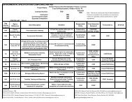
c. Type II Independent External Peer <strong>Review</strong> (IEPR) Determination (Section 2035). This<br />
project does not trigger WRDA 2007 Section 2035 factors for Safety Assurance <strong>Review</strong> (termed<br />
Type II IEPR in EC 1165-2-209) and therefore, a review under Section 2035 is should not be<br />
warranted. The factors in determining whether a review of design and construction activities of a<br />
project is necessary are based on the EC 1165-2-209 Type II IEPR Risk Informed Decision<br />
Process. The following EC 1165-2-209 risk decision criteria are followed by a statement that<br />
forms the basis for the Type II IEPR exclusion.<br />
1. The Federal action is justified by life safety or the failure of the project would pose a significant<br />
threat to human life.<br />
The <strong>Jacksonville</strong> District has not identified any concerns with respect to life safety since the level<br />
of water associated with the project features would not create an adverse condition for life safety.<br />
The primary rationale for the levee system is to train the water in a southerly direction and to<br />
minimize any outflanking effects that might otherwise be experienced on adjacent lands.<br />
2. The project involves the use of innovative materials or techniques where the engineering is<br />
based on novel methods, presents complex challenges for interpretations, contains precedentsetting<br />
methods or models, or presents conclusions that are likely to change prevailing practices.<br />
The project involves standard materials and techniques for the managing for stormwater and the<br />
installation of constructed features. Consequently, no unique materials or techniques are<br />
proposed for this project. Subsequently, the methods utilized do not set a precedent and are not<br />
likely to change prevailing practices.<br />
3. The project design requires redundancy, resiliency, and robustness.<br />
(1) Redundancy. Redundancy is the duplication of critical components of a system with the<br />
intention of increasing reliability of the system, usually in the case of a backup or fail-safe.<br />
(2) Resiliency. Resiliency is the ability to avoid, minimize, withstand, and recover from the effects<br />
of adversity, whether natural or manmade, under all circumstances of use.<br />
(3) Robustness. Robustness is the ability of a system to continue to operate correctly across a<br />
wide range of operational conditions (the wider the range of conditions, the more robust the<br />
system), with minimal damage, alteration or loss of functionality, and to fail gracefully outside of<br />
that range.<br />
This project principal function is to provide flood risk management while restoring the hydrology to<br />
a stressed ecosystem. The pump stations that are being designed/constructed have redundant<br />
pumps proposed to allow for interrupted operation and repair and replacement without losing the<br />
required capacity to maintain the current flood protection for the neighboring properties.<br />
Additionally, there is diesel generated backup power in the event of a loss of electricity. The<br />
pump stations can be controlled via on-site personnel or from the command center of the South<br />
Florida Water Management District in West Palm Beach, FL. The design and construction of the<br />
19
facilities was performed in anticipation of adverse conditions that can arise in South Florida. The<br />
buildings have been design to withstand hurricane force winds up to 140 mph at a reoccurrence<br />
level of 200 years.<br />
4. The project has unique construction sequencing or a reduced or overlapping design<br />
construction schedule; for example, significant project features accomplished using the Design-<br />
Build or Early Contractor Involvement (ECI) delivery systems.<br />
Construction sequencing is essential to all construction projects at some level. The <strong>Picayune</strong><br />
<strong>Strand</strong> <strong>Project</strong> does involve construction sequencing; however it is for the purpose of financial<br />
convenience and logical implementation of improvements. A reduced or overlapping<br />
design/construction is not part of this project like it would be expected for a design/build<br />
approach.<br />
6. MODEL CERTIFICATION AND APPROVAL<br />
Engineering Models. The <strong>Picayune</strong> <strong>Strand</strong> <strong>Restoration</strong> <strong>Project</strong> does not use any<br />
engineering models that have not been approved for use by USACE. The engineering<br />
models are:<br />
MIKESHE/Mike11 (v2009): MikeShe/Mike11 is an integrated surface watergroundwater<br />
dynamic modeling system developed by the Danish Hydraulic Institute. It<br />
can simulate all of the major land phase hydrological processes and is comprised of<br />
several independent modules that represent each hydrological process. The program<br />
will be used to update the flood routings and resulting stage-frequency relationships for<br />
<strong>Picayune</strong> <strong>Strand</strong>.<br />
MIKE FLOOD (v2008): The Danish Hydraulic Institute (DHI) MIKE FLOOD is a<br />
comprehensive flood modeling package covering all the major aspects of flood<br />
modeling. MIKE FLOOD combines the capabilities of MIKE 11 and MIKE 21. MIKE<br />
FLOOD integrates flood plains, canals, roadways, levee and etc. into one package.<br />
MIKE FLOOD can simulate flood waves over dry land in channels and on floodplains<br />
associated with a dam breach. MIKE FLOOD will integrate the hydrodynamic models<br />
MIKE 21 and MIKE 11 in support of the tie-back levee breach analyses and<br />
evaluations.<br />
MIKE 21: MIKE 21 is a 2-D hydrodynamic model that simulates flow and sediment<br />
transport. MIKE 21 is integrated and dynamically linked to MIKE 11 to simulate flood<br />
flows in a combined river and floodplain environment.<br />
MIKE 11: MIKE 11 is a 1-D hydrodynamic model that simulates flow in 1-D channels,<br />
flows over a variety of structures including broad-crested weirs, dam break structures,<br />
and user-defined structures. MIKE 11 is integrated and dynamically linked to MIKE 21<br />
to simulate flood flows in a combined river and floodplain environment.<br />
MIKE Zero: MIKE Zero is MIKE FLOOD’s fully integrated GUI used to develop model<br />
grids, to set up simulations, for pre- and post-processing analysis, and to present and<br />
visualize model results. Post processing capabilities include extracting a time series of<br />
surface elevations and extracting profile series, performing statistical values on time<br />
series, line series, matrix series or volume series, rotating and transforming 2-D data,<br />
pre- and post-processing in a Geographic Information Systems (GIS) integrated<br />
environment, composing plots, and animating video.<br />
20
ESRI ArcMap 9.3.1.: Environmental Systems Research Institute's GIS software was<br />
utilized to provide geospatial information for hydrodynamic model pre-processing<br />
including land use, lidar, and geographic feature alignments.<br />
HEC-RAS 4.1.: The Hydrologic Engineering Center's River Analysis System(HEC-<br />
RAS) program provides the capability to perform one-dimensional unsteady flow river<br />
hydraulics calculations. The program was utilized to model maximum inundation extent<br />
to help establish MIKE-21 mesh domain.<br />
SMS (Version 10.0): The Surface-Water Modeling System (SMS) is an intuitive preand<br />
post-processor for building grids, viewing solutions, and many other specialized<br />
tasks. This software package was developed by Brigham Young University. The SMS<br />
software package was used to construct finite element grids for the wind and wave<br />
analysis portion of the wave run-up and embankment over-wash evaluation for pump<br />
station tie-back levees. Grids included a coarse resolution grid of the <strong>Picayune</strong> <strong>Strand</strong><br />
and refined resolution grids for Port of the Islands, Private Lands and 6L’s Farm.<br />
Compaq Visual Fortran (Professional Edition 6.1.0): Compaq Visual Fortran is a<br />
flexible Fortran programming language compiler that supports Fortran 66, Fortran 77,<br />
Fortran 90, and Fortran 95. The Compaq Visual Fortran developer was used to code<br />
both the ACES source code equations and Bretschneider’s derivations into Fortran<br />
programs for calculating wave run-up, wave over-wash, and wind set-up and set-down.<br />
Microsoft Excel spreadsheet tools have been developed by the Risk Management<br />
Center in a modular format. The workbooks follow a step-by-step procedure to<br />
determine the conditional probabilities needed to develop a system response curve.<br />
Tables are presented within each workbook to provide guidance on the estimation of<br />
conditional probabilities. These tables have been developed to model the physical<br />
processes so far as practical. The probabilities have been assessed using the expert<br />
judgment of workshop attendees. Where practical, the probabilities have been<br />
anchored to historic data.<br />
GeoStudio 2004 containing both Seep/W and Slope/W from GEO-SLOPE, Inc. out of<br />
Alberta, Canada. Seep/W is a numerical model that can mathematically simulate the<br />
real physical process of water flowing through a particulate medium through the use of<br />
finite elements. This program is used to model the flow of water through embankment,<br />
foundation, and other features as required in pursuit of solutions that adequately<br />
address factors of safety against piping and uplift. Slope 2D is a numerical model that<br />
utilizes limit equilibrium methods to analyze the stability of earth structures through<br />
inputs of geometry, soil strength, pore-water pressure, soil-structure interactions, and<br />
imposed loading. It is also capable of performing probabilistic stability analyses<br />
through a Monte Carlo process.<br />
Groundwater Modeling System (GMS) version 6.5. Department of Defense. GMS<br />
provides an integrated and comprehensive computational environment for simulating<br />
subsurface flow, contaminant fate/transport, and the efficacy and design of remediation<br />
systems. This program is used to model the flow of water through embankment,<br />
foundation, and other features as required in pursuit of solutions that adequately<br />
address factors of safety against piping and uplift.<br />
7. BUDGET AND SCHEDULE<br />
21
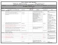
a. Design and Construction Phase <strong>Project</strong> Milestones. <strong>Project</strong> review milestones are<br />
contained in the following table.<br />
DQC, ATR, and BCOE SCHEDULE<br />
PRODUCT Activity Preparer Date<br />
H&H Analysis 1 SAJ FY11<br />
QCR (Internal <strong>Review</strong>) 06/2011<br />
ATR 08/2011<br />
** BCOE TBD<br />
Advertise<br />
Merritt Pumping Station Construction Parsons Jan 11 – Aug 12<br />
Faka Union Pumping Station<br />
Parsons<br />
Construction Jan 11 – Dec 13<br />
Protection Features SAJ FY11<br />
Port of the Islands 2<br />
Preliminary P&S QCR (Internal <strong>Review</strong>) SAJ Dec 11 – Jan 12<br />
Intermediate P&S QCR (Internal <strong>Review</strong>) SAJ May – Jun 12<br />
ATR Jun – July 12<br />
Pre-Final Design QCR SAJ Sept 12<br />
ATR Sept – Oct 12<br />
Final QCR SAJ Nov 12<br />
** BCOE Nov – Dec 12<br />
Advertise Dec 12 – Feb 13<br />
Construction May 13 – Dec 13<br />
Private Lands 3<br />
Preliminary P&S QCR SAJ Nov 12<br />
Intermediate P&S QCR SAJ Aug 13<br />
ATR Apr 13<br />
Pre–Final Design QCR SAJ Aug 13<br />
ATR Sept 13<br />
Final QCR SAJ Dec 13<br />
**BCOE Dec 12 – Jan 13<br />
Advertise Jan – Feb 13<br />
Construction May 14 – Mar 15<br />
6L’s 4<br />
Preliminary P&S QCR SAJ Jan – Feb 13<br />
Intermediate P&S QCR SAJ Aug 13<br />
ATR Aug 13<br />
Pre-Final Design QCR SAJ Jan 14<br />
ATR Feb 14<br />
22
Final QCR SAJ Apr 14<br />
**BCOE Apr – May 14<br />
Advertise Jun – July 14<br />
Construction Oct 14 – Nov 15<br />
Miller Pumping Station SAJ FY11<br />
Intermediate P&S QCR (Internal <strong>Review</strong>) Oct 11<br />
ATR Dec 11<br />
BCOE Dec 11<br />
Final P&S QCR SAJ July 12<br />
ATR Aug 12<br />
**BCOE Aug 12<br />
Advertise Dec 12 – Feb 13<br />
1 H&H Analysis – The H&H analysis includes the hydrologic and hydraulic analysis of the entire<br />
project in an effort to get a gross level (Tier 1) of understanding of the stages that will occur<br />
before and after the implementation of the pump stations and protection features. Once the Tier<br />
1 model is formulated, more specific analyses (Tier 2 and Tier 3) will be conducted as part of the<br />
H&H scope of work that will more accurately define the stages at areas determined to be of<br />
significance.<br />
2 Port of the Islands – Port of the Islands is an existing mixed use community located at the<br />
southern extreme of the <strong>Picayune</strong> <strong>Strand</strong> <strong>Restoration</strong> <strong>Project</strong>, adjacent to the Faka Union Canal<br />
and on both the north and south side of US 41. The community consists of single and multifamily<br />
residential, hotel/restaurant, marina and gun club.<br />
3 Private Lands – To the west of the Miller Canal and Miller Blvd. there are some remaining homes<br />
th<br />
nd<br />
between 54 Ave. and 62 Ave. that are not part of the restoration project. These homes will<br />
remain after construction of the pump stations and levees. As part of the overall project, it is<br />
anticipated that an extension of the Miller Pump Station Tie-Back Levee may need to be<br />
extended as part of the Protection Features. The extension would be to address potential staging<br />
on the private lands.<br />
4 6L’s – To the southwest of the <strong>Picayune</strong> <strong>Strand</strong> <strong>Restoration</strong> <strong>Project</strong>, north of US 41 there is an<br />
existing tomato farm called the 6L’s Farm. The H&H modeling that will be performed as part of<br />
the Protection Features will evaluate the possible effects could occur as a result of the restoration<br />
project and what protection features may be necessary to compensate for those possible stages.<br />
b. ATR Budget Estimate. FY11 ATR cost estimates will range $150,000-$200,000.<br />
c. Construction and Operations and Maintenance Phase Milestones.<br />
OMRR&R Phase and O&M Manual– Jan 2012<br />
8. POINTS OF CONTACT<br />
Per guidance, the names of the following individual will not be posted on the Internet with the<br />
<strong>Review</strong> <strong>Plan</strong>. Their titles and responsibilities are listed below.<br />
23
<strong>Jacksonville</strong> District POCs:<br />
<strong>Review</strong> <strong>Plan</strong>, ATR and IEPR Process:<br />
<strong>Project</strong> Information, PM:<br />
Jimmy D. Matthews<br />
904-232-2087<br />
Jimmy.D.Matthews@usace.army.mil<br />
Lacy Shaw<br />
904-232-1550<br />
Lacy.E.Shaw@usace.army.mil<br />
CPT Erica Lager<br />
904-232-3648<br />
Erica.D.Lager@usace.army.mil<br />
<strong>Project</strong> Information, <strong>Project</strong> Engineer:<br />
Autumn Ziegler<br />
904-232-1956<br />
Autumn.N.Ziegler@usace.army.mil<br />
David Dudley<br />
904-232-3712<br />
David.F.Dudley@usace.army.mil<br />
South Atlantic Division:<br />
James C. Truelove<br />
404-562-5121<br />
James.C.Truelove@usace.army.mil<br />
24