

Understanding Neutron Radiography Reading II-TNR of Materials
Understanding Neutron Radiography Reading II-TNR of Materials
Understanding Neutron Radiography Reading II-TNR of Materials

You also want an ePaper? Increase the reach of your titles
YUMPU automatically turns print PDFs into web optimized ePapers that Google loves.
<strong>Understanding</strong><br />
<strong>Neutron</strong> <strong>Radiography</strong><br />
<strong>Reading</strong> <strong>II</strong><br />
My ASNT Level <strong>II</strong>I,<br />
Pre-Exam Preparatory<br />
Self Study Notes<br />
27 June 2015<br />
Charlie Chong/ Fion Zhang<br />
http://homework55.com/apphysicsb/ap5-28-08/
Nuclear Applications<br />
Charlie Chong/ Fion Zhang
Nuclear Applications<br />
Charlie Chong/ Fion Zhang
The Magical Book <strong>of</strong> <strong>Neutron</strong> <strong>Radiography</strong><br />
Charlie Chong/ Fion Zhang
Charlie Chong/ Fion Zhang
ASNT Certification Guide<br />
NDT Level <strong>II</strong>I / PdM Level <strong>II</strong>I<br />
NR - <strong>Neutron</strong> Radiographic Testing<br />
Length: 4 hours Questions: 135<br />
1. Principles/Theory<br />
• Nature <strong>of</strong> penetrating radiation<br />
• Interaction between penetrating radiation and matter<br />
• <strong>Neutron</strong> radiography imaging<br />
• Radiometry<br />
2. Equipment/<strong>Materials</strong><br />
• Sources <strong>of</strong> neutrons<br />
• Radiation detectors<br />
• Non-imaging devices<br />
Charlie Chong/ Fion Zhang
3. Techniques/Calibrations<br />
• Blocking and filtering<br />
• Multifilm technique<br />
• Enlargement and projection<br />
• Stereoradiography<br />
• Triangulation methods<br />
• Autoradiography<br />
• Flash <strong>Radiography</strong><br />
• In-motion radiography<br />
• Fluoroscopy<br />
• Electron emission radiography<br />
• Micro-radiography<br />
• Laminography (tomography)<br />
• Control <strong>of</strong> diffraction effects<br />
• Panoramic exposures<br />
•Gaging<br />
• Real time imaging<br />
• Image analysis techniques<br />
Charlie Chong/ Fion Zhang
4. Interpretation/Evaluation<br />
• Image-object relationships<br />
• Material considerations<br />
• Codes, standards, and specifications<br />
5. Procedures<br />
• Imaging considerations<br />
• Film processing<br />
• Viewing <strong>of</strong> radiographs<br />
• Judging radiographic quality<br />
6. Safety and Health<br />
• Exposure hazards<br />
• Methods <strong>of</strong> controlling radiation exposure<br />
• Operation and emergency procedures<br />
Reference Catalog Number<br />
NDT Handbook, Third Edition: Volume 4,<br />
Radiographic Testing 144<br />
ASM Handbook Vol. 17, NDE and QC 105<br />
Charlie Chong/ Fion Zhang
Charlie Chong/ Fion Zhang
Fion Zhang at Shanghai<br />
27th June 2015<br />
http://meilishouxihu.blog.163.com/<br />
Charlie Chong/ Fion Zhang
Greek<br />
Alphabet<br />
Charlie Chong/ Fion Zhang
Charlie Chong/ Fion Zhang<br />
http://greekhouse<strong>of</strong>fonts.com/
Charlie Chong/ Fion Zhang
Why <strong>Neutron</strong> <strong>Radiography</strong>?<br />
"finding lead in a paraffin block (or a needle in a haystack) would work for x<br />
rays while looking for paraffin in a lead block or a straw in a needle-stack<br />
would work for neutrons."<br />
Charlie Chong/ Fion Zhang
Why <strong>Neutron</strong> <strong>Radiography</strong>?<br />
"finding lead in a paraffin block (or a needle in a haystack) would work for x<br />
rays while looking for paraffin in a lead block or a straw in a needle-stack<br />
would work for neutrons."<br />
Charlie Chong/ Fion Zhang
Why <strong>Neutron</strong> <strong>Radiography</strong>?<br />
"finding lead in a paraffin block (or a needle in a haystack) would work for x<br />
rays while looking for paraffin in a lead block or a straw in a needle-stack<br />
would work for neutrons."<br />
Charlie Chong/ Fion Zhang
■<br />
http://minerals.usgs.gov/minerals/pubs/commodity/<br />
Charlie Chong/ Fion Zhang
<strong>Neutron</strong> Cross Section <strong>of</strong> the elements<br />
■<br />
http://periodictable.com/Properties/A/<strong>Neutron</strong>CrossSection.html<br />
Charlie Chong/ Fion Zhang
IVONA TTS Capable.<br />
Charlie Chong/ Fion Zhang<br />
http://www.naturalreaders.com/
<strong>Reading</strong> <strong>II</strong><br />
Content<br />
• <strong>Reading</strong> One: E748<br />
• <strong>Reading</strong> Two: ASMHB17-NRT<br />
• <strong>Reading</strong> Three: E1316<br />
• <strong>Reading</strong> Four: <strong>Neutron</strong>s provide unique penetrating radiation<br />
Charlie Chong/ Fion Zhang
<strong>Reading</strong>-1<br />
E748<br />
Charlie Chong/ Fion Zhang
1. Scope<br />
1.1 Purpose - Practices to be employed for the radiographic examination <strong>of</strong><br />
materials and components with thermal neutrons are outlined herein. They<br />
are intended as a guide for the production <strong>of</strong> neutron radiographs that<br />
possess consistent quality characteristics, as well as aiding the user to<br />
consider the applicability <strong>of</strong> thermal neutron radiology (radiology, radiographic,<br />
and related terms are defined in Terminology E 1316). Statements concerning<br />
preferred practice are provided without a discussion <strong>of</strong> the technical<br />
background for the preference. The necessary technical background can be<br />
found in Refs (1-16).<br />
Charlie Chong/ Fion Zhang
1.2 Limitations - Acceptance standards have not been established for any<br />
material or production process (see Section 5 on Basis <strong>of</strong> Application).<br />
Adherence to the practices will, however, produce reproducible results that<br />
could serve as standards. <strong>Neutron</strong> radiography, whether performed by means<br />
<strong>of</strong> a reactor, an accelerator, subcritical assembly, or radioactive source, will<br />
be consistent in sensitivity and resolution only if the consistency <strong>of</strong> all details<br />
<strong>of</strong> the technique, such as neutron source, collimation, geometry, film, etc., is<br />
maintained through the practices. These practices are limited to the use <strong>of</strong><br />
photographic or radiographic film in combination with conversion screens for<br />
image recording; other imaging systems are available. Emphasis is placed on<br />
the use <strong>of</strong> nuclear reactor neutron sources.<br />
1.3 Interpretation and Acceptance Standards - Interpretation and acceptance<br />
standards are not covered by these practices. Designation <strong>of</strong> accept-reject<br />
standards is recognized to be within the cognizance 认 定 <strong>of</strong> product<br />
specifications.<br />
Charlie Chong/ Fion Zhang
1.4 Safety Practices - General practices for personnel protection against<br />
neutron and associated radiation peculiar to the neutron radiologic process<br />
are discussed in Section 17. For further information on this important aspect<br />
<strong>of</strong> neutron radiology, refer to current documents <strong>of</strong> the National Committee on<br />
Radiation Protection and Measurement, the Code <strong>of</strong> Federal Regulations, the<br />
U.S. Nuclear Regulatory Commission, the U.S. Department <strong>of</strong> Energy, the<br />
National Institute <strong>of</strong> Standards and Technology, and to applicable state and<br />
local codes.<br />
1.5 Other Aspects <strong>of</strong> the <strong>Neutron</strong> Radiographic Process - For many<br />
important aspects <strong>of</strong> neutron radiography such as technique, files, viewing <strong>of</strong><br />
radiographs, storage <strong>of</strong> radiographs, film processing, and record keeping,<br />
refer to Guide E 94. (See Section 2.)<br />
1.6 The values stated in either SI or inch-pound units are to be regarded as<br />
the standard.<br />
Charlie Chong/ Fion Zhang
1.7 This standard does not purport to address all <strong>of</strong> the safety concerns, if<br />
any, associated with its use. It is the responsibility <strong>of</strong> the user <strong>of</strong> this standard<br />
to establish appropriate safety and health practices and determine the<br />
applicability <strong>of</strong> regulatory limitations prior to use. (For more specific safety<br />
information see 1.4.)<br />
Charlie Chong/ Fion Zhang
2. Referenced Documents<br />
2.1 ASTM Standards:<br />
• E 94 Guide for Radiographic Testing<br />
• E 543 Practice for Evaluating Agencies that Perform Nondestructive<br />
Testing E 545 Method for Determining Image Quality in Direct Thermal<br />
<strong>Neutron</strong> Radiographic Examination<br />
• E 803 Method for Determining the L/D Ratio <strong>of</strong> <strong>Neutron</strong> <strong>Radiography</strong><br />
Beams E 1316 Terminology for Nondestructive Examinations<br />
• E 1496 Test Method for <strong>Neutron</strong> Radiographic Dimensional<br />
Measurements<br />
Charlie Chong/ Fion Zhang
2.2 ASNT Standard:<br />
• SNT-TC-1A Recommended Practice for Personnel Qualification and<br />
Certification<br />
2.3 ANSI Standard:<br />
• ANSI/ASNT- P- 89 Standard for Qualification and Certification <strong>of</strong><br />
Nondestructive Testing Personnel<br />
2.4 Military Standard:<br />
• MIL-STD-410 Nondestructive Testing Personnel Qualification and<br />
Certification<br />
Charlie Chong/ Fion Zhang
3. Terminology<br />
3.1 Definitions - For definitions <strong>of</strong> terms used in these practices, see<br />
Terminology E 1316, Section H.<br />
4. Significance and Use<br />
4.1 These practices include types <strong>of</strong> materials to be examined, neutron<br />
radiographic examination techniques, neutron production and collimation<br />
methods, radiographic film, and converter screen selection. Within the<br />
present state <strong>of</strong> the neutron radiologic art, these practices are generally<br />
applicable to specific material combinations, processes, and techniques.<br />
Charlie Chong/ Fion Zhang
5. Basis <strong>of</strong> Application<br />
5.1 Personnel Qualification - Nondestructive testing (NDT) personnel shall be<br />
qualified in accordance with a nationally recognized NDT personnel<br />
qualification practice or standard such as ANSI/ASNT-CP-189, SNT-TC-1A,<br />
MIL-STD-410, or a similar document. The practice or standard used and its<br />
applicable revision shall be specified in the contractual agreement between<br />
the using parties.<br />
5.2 Qualification <strong>of</strong> Nondestructive Agencies - If specified in the contractual<br />
agreement, NDT agencies shall be qualified and evaluated as described in<br />
Practice E 543. The applicable edition <strong>of</strong> Practice E 543 shall be specified in<br />
the contractual agreement.<br />
5.3 Procedures and Techniques - The procedures and techniques to be used<br />
shall be as described in these practices unless otherwise specified. Specific<br />
techniques may be specified in the contractual agreement.<br />
Charlie Chong/ Fion Zhang
5.4 Extent <strong>of</strong> Examination - The extent <strong>of</strong> examination shall be in accordance<br />
with Section 16 unless otherwise specified.<br />
5.5 Reporting Criteria/Acceptance Criteria - Reporting criteria for the<br />
examination results shall be in accordance with 1.3 unless otherwise<br />
specified. Acceptance criteria (for example, for reference radiographs) shall<br />
be specified in the contractual agreement.<br />
5.6 Reexamination <strong>of</strong> Repaired/Reworked Items - Reexamination <strong>of</strong><br />
repaired/reworked items is not addressed in these practices and, if required,<br />
shall be specified in the contractual agreement.<br />
Charlie Chong/ Fion Zhang
6. <strong>Neutron</strong> <strong>Radiography</strong><br />
6.1 The Method - <strong>Neutron</strong> radiography is basically similar to X radiography in<br />
that both techniques employ radiation beam intensity modulation by an object<br />
to image macroscopic object details. X rays or gamma rays are replaced by<br />
neutrons as the penetrating radiation in a through-transmission examination.<br />
Since the absorption characteristics <strong>of</strong> matter for X rays and neutrons differ<br />
drastically, the two techniques in general serve to complement one another.<br />
6.2 Facilities - The basic neutron radiography facility consists <strong>of</strong> a source <strong>of</strong><br />
fast neutrons, a moderator, a gamma filter, a collimator, a conversion screen,<br />
a film image recorder or other imaging system, a cassette, and adequate<br />
biological shielding and interlock systems. A schematic diagram <strong>of</strong> a<br />
representative neutron radiography facility is illustrated in Fig. 1.<br />
6.3 Thermalization - The process <strong>of</strong> slowing down neutrons by permitting the<br />
neutrons to come to thermal equilibrium with their surroundings; see definition<br />
<strong>of</strong> thermal neutrons in Terminology E 1316, Section H.<br />
Charlie Chong/ Fion Zhang
FIG. 1 Typical <strong>Neutron</strong> <strong>Radiography</strong> Facility with Divergent Collimator<br />
Charlie Chong/ Fion Zhang
7. <strong>Neutron</strong> Sources<br />
7.1 General - The thermal neutron beam may be obtained from:<br />
■<br />
■<br />
■<br />
■<br />
a nuclear reactor,<br />
a subcritical assembly,<br />
a radioactive neutron source,<br />
or an accelerator.<br />
<strong>Neutron</strong> radiography has been achieved successfully with all four sources. In<br />
all cases the initial neutrons generated possess high energies and must be<br />
reduced in energy (moderated) to be useful for thermal neutron radiography.<br />
This may be achieved by surrounding the source with light materials such as:<br />
■<br />
■<br />
■<br />
■<br />
■<br />
■<br />
water,<br />
oil,<br />
plastic,<br />
paraffin,<br />
beryllium, or<br />
graphite.<br />
Charlie Chong/ Fion Zhang
The preferred moderator will be dependent on the constraints dictated by the<br />
energy <strong>of</strong> the primary neutrons, which will in turn be dictated by neutron beam<br />
parameters such as thermal neutron yield requirements, cadmium ratio, and<br />
beam gamma ray contamination. The characteristics <strong>of</strong> a particular system for<br />
a given application are left for the seller and the buyer <strong>of</strong> the service to decide.<br />
Characteristics and capabilities <strong>of</strong> each type <strong>of</strong> source are referenced in the<br />
References section. A general comparison <strong>of</strong> sources is shown in Table 1.<br />
Charlie Chong/ Fion Zhang
TABLE 1 Comparison <strong>of</strong> Thermal <strong>Neutron</strong> Sources<br />
Charlie Chong/ Fion Zhang
7.2 Nuclear Reactors - Nuclear reactors are the preferred thermal neutron<br />
source in general, since high neutron fluxes are available and exposures can<br />
be made in a relatively short time span. The high neutron intensity makes it<br />
possible to provide a tightly collimated beam; therefore, high-resolution<br />
radiographs can be produced.<br />
U g = Dt/L<br />
Charlie Chong/ Fion Zhang
7.3 Subcritical Assembly - A subcritical assembly is achieved by the addition<br />
<strong>of</strong> sufficient fissionable material surrounding a moderated source <strong>of</strong> neutrons,<br />
usually a radioisotope source. Although the total thermal neutron yield is<br />
smaller than that <strong>of</strong> a nuclear reactor, such a system <strong>of</strong>fers the attractions <strong>of</strong><br />
adequate image quality in a reasonable exposure time, relative ease <strong>of</strong><br />
licensing, adequate neutron yield for most industrial applications, and the<br />
possibility <strong>of</strong> transportable operation.<br />
Charlie Chong/ Fion Zhang
Subcritical Assembly<br />
Critical mass<br />
A critical mass is the smallest amount <strong>of</strong> fissile material needed for a<br />
sustained nuclear chain reaction. The critical mass <strong>of</strong> a fissionable material<br />
depends upon its nuclear properties (specifically, the nuclear fission crosssection),<br />
its density, its shape, its enrichment, its purity, its temperature, and<br />
its surroundings. The concept is important in nuclear weapon design.<br />
Explanation <strong>of</strong> criticality<br />
When a nuclear chain reaction in a mass <strong>of</strong> fissile material is self-sustaining,<br />
the mass is said to be in a critical state in which there is no increase or<br />
decrease in power, temperature, or neutron population.<br />
A numerical measure <strong>of</strong> a critical mass is dependent on the effective neutron<br />
multiplication factor k, the average number <strong>of</strong> neutrons released per fission<br />
event that go on to cause another fission event rather than being absorbed or<br />
leaving the material. When k = 1, the mass is critical, and the chain reaction is<br />
barely self-sustaining.<br />
Charlie Chong/ Fion Zhang<br />
https://en.wikipedia.org/wiki/Critical_mass
A subcritical mass is a mass <strong>of</strong> fissile material that does not have the ability to<br />
sustain a fission chain reaction. A population <strong>of</strong> neutrons introduced to a<br />
subcritical assembly will exponentially decrease. In this case, k < 1. A steady<br />
rate <strong>of</strong> spontaneous fissions causes a proportionally steady level <strong>of</strong> neutron<br />
activity. The constant <strong>of</strong> proportionality increases as k increases.<br />
A supercritical mass is one where there is an increasing rate <strong>of</strong> fission. The<br />
material may settle into equilibrium (i.e. become critical again) at an elevated<br />
temperature/power level or destroy itself, by which equilibrium is reached. In<br />
the case <strong>of</strong> supercriticality, k > 1<br />
Charlie Chong/ Fion Zhang<br />
https://en.wikipedia.org/wiki/Critical_mass
7.4 Accelerator Sources - Accelerators used for thermal neutron radiography<br />
have generally been <strong>of</strong> the low-voltage type which utilize the 3 H(d,n) 4 He<br />
reaction, high-energy X-ray machines in which the (x,n) reaction is applied<br />
and Van de Graaff and other high-energy accelerators which employ<br />
reactions such as 9 Be(d,n) 10 B. In all cases, the targets are surrounded by a<br />
moderator to reduce the neutrons to thermal energies. The total neutron<br />
yields <strong>of</strong> such machines can be on the order <strong>of</strong> 10 12·n·s -1 ; the thermal neutron<br />
flux <strong>of</strong> such sources before collimation can be on the order <strong>of</strong> 10 9 n·cm -2·s -1 ,<br />
for example, the yield from a Van de Graaff accelerator.<br />
Total flux Ф 1012·n·s-1<br />
D<br />
I<br />
L<br />
I = Ф/16(L/D)<br />
Charlie Chong/ Fion Zhang
Accelerator Sources-Linear Accelerator<br />
Charlie Chong/ Fion Zhang<br />
http://atomic.lindahall.org/what-is-an-atom-smasher.html
Accelerator Sources-Cyclotron<br />
Charlie Chong/ Fion Zhang<br />
http://atomic.lindahall.org/what-is-an-atom-smasher.html
7.5 Isotopic Sources - Many isotopic sources have been employed for<br />
neutron radiologic applications. Those that have been most widely utilized are<br />
outlined in Table 2. Radioactive sources <strong>of</strong>fer the best possibility for portable<br />
operation. However, because <strong>of</strong> the relatively low neutron yield, the exposure<br />
times are usually long for a given image quality. The isotopic source252Cf<br />
<strong>of</strong>fers a number <strong>of</strong> advantages for thermal neutron radiology, namely, low<br />
neutron energy and small physical size, both <strong>of</strong> which lead to efficient neutron<br />
moderation, and the possibility for high total neutron yields.<br />
TABLE 2 Radioactive Sources Employed for Thermal <strong>Neutron</strong> <strong>Radiography</strong><br />
A: These comments compare sources in the table.<br />
Charlie Chong/ Fion Zhang
8. Imaging Methods and Conversion Screens<br />
8.1 General - <strong>Neutron</strong>s are nonionizing particulate radiation that have little<br />
direct effect on radiographic film. To obtain a neutron radiographic image on<br />
film, a conversion screen is normally employed; upon neutron capture,<br />
screens emit prompt and delayed decay products in the form <strong>of</strong> nuclear<br />
radiation or light. In all cases the screen should be placed in intimate contact<br />
with the radiographic film in order to obtain sharp images.<br />
8.2 Direct Method - In the direct method, a film is placed on the source side <strong>of</strong><br />
the conversion screen (front film) and exposed to the neutron beam together<br />
with the conversion screen. Electron emission upon neutron capture is the<br />
mechanism by which the film is exposed in the case <strong>of</strong> gadolinium conversion<br />
screens.<br />
Charlie Chong/ Fion Zhang
The screen is generally one <strong>of</strong> the following types:<br />
1. a free-standing gadolinium metal screen accessible to film on both sides;<br />
2. a sapphire coated, vapordeposited gadolinium screen on a substrate<br />
such as aluminum; or<br />
3. a light-emitting fluorescent screen such as gadolinium oxysulfide or<br />
6<br />
LiF/ZnS. Exposure <strong>of</strong> an additional film (without object) is <strong>of</strong>ten useful to<br />
resolve artifacts that may appear in radiographs.<br />
Such artifacts could result from screen marks, excess pressure, light leaks,<br />
development, or nonuniform film. In the case <strong>of</strong> light-emitting conversion<br />
screens, it is recommended that the spectral response <strong>of</strong> the light emission<br />
be matched as closely as possible to that <strong>of</strong> the film used for optimum results.<br />
The direct method should be employed whenever high-resolution radiographs<br />
are required, and high beam contamination <strong>of</strong> low-energy gamma rays or<br />
highly radioactive objects do not preclude its use.<br />
Charlie Chong/ Fion Zhang
8.3 Indirect Method - This method makes use <strong>of</strong> conversion screens that can<br />
be made temporarily radioactive by neutron capture. The conversion screen<br />
is exposed alone to the neutronimaging beam; the film is not present.<br />
Candidate conversion materials include (1) rhodium, (2) gold, (3) indium, and<br />
(4) dysprosium.<br />
Indium and dysprosium are recommended with dysprosium yielding the<br />
greater speed and emitting less energetic gamma radiation.<br />
It is recommended that the conversion screens be activated in the neutron<br />
beam for a maximum <strong>of</strong> three half-lives (3 x T ½ ) . Further neutron irradiation<br />
will result in a negligible amount <strong>of</strong> additional induced activity. After irradiation,<br />
the conversion screens should be placed in intimate contact with a<br />
radiographic film in a vacuum cassette, or other light-tight assembly in which<br />
good contact can be maintained between the radiographic film and<br />
radioactive screen.<br />
X- ay intensification screens may be used to increase the speed <strong>of</strong> the<br />
autoradiographic process if desired.<br />
Charlie Chong/ Fion Zhang
For the indirect type <strong>of</strong> exposure, the material from which the cassette is<br />
fabricated is immaterial as there are no neutrons to be scattered in the<br />
exposure process. In this case, as in the activation process, there is little to<br />
be gained for conversion screen-film exposures extending beyond three halflives.<br />
It is recommended that this method be employed whenever the neutron<br />
beam is highly contaminated with gamma rays, which in turn cause film<br />
fogging and reduced contrast sensitivity, or when highly radioactive objects<br />
are to be radiographed. In short, this method is beam gamma-insensitive.<br />
8.4 Other Imaging Systems - The scope <strong>of</strong> these practices is limited to film<br />
imaging (see 1.2). However, other imaging systems such as track-etch or<br />
radioscopic systems are available.<br />
Charlie Chong/ Fion Zhang
Track-etch<br />
Ion tracks are damage-trails created by swift heavy ions penetrating through<br />
solids, which may be sufficiently-contiguous for chemical etching in a variety<br />
<strong>of</strong> crystalline, glassy, and/or polymeric solids.[1][2] They are associated with<br />
cylindrical damage-regions several nanometers in diameter[3][4] and can be<br />
studied by Rutherford backscattering spectrometry (RBS), transmission<br />
electron microscopy (TEM), small-angle neutron scattering (SANS), smallangle<br />
X-ray scattering (SAXS) or gas permeation.<br />
"Fresh" (latent or unetched)<br />
Californium-252 fission tracks[1] in<br />
a chromite (FeCr 2 O 4 ) grain from the<br />
Allende meteorite, showing up in a<br />
weak-beam darkfield TEM image<br />
which lights up the strain-fields<br />
around the 40Å-diameter trackdamage<br />
cores. This work confirmed<br />
chromite's ability to record nuclear<br />
particle tracks in spite <strong>of</strong> its<br />
relatively low resistivity.<br />
Charlie Chong/ Fion Zhang
Track-etch<br />
Charlie Chong/ Fion Zhang
More <strong>Reading</strong> on Radioscopy<br />
■ http://www.ndt.net/article/wcndt00/papers/idn284/idn284.htm<br />
■ http://www.nationalboard.org/Index.aspx?pageID=164&ID=199<br />
Charlie Chong/ Fion Zhang
9. <strong>Neutron</strong> Collimators<br />
9.1 General - <strong>Neutron</strong> sources for thermal neutron radiology generally involve<br />
a sizeable moderator region in which the neutron motion is highly<br />
multidirectional. Collimators are required to produce a beam and thereby<br />
produce adequate image resolution capability in a neutron radiology facility. It<br />
should be noted that in the definitions <strong>of</strong> collimator parameters, it is assumed<br />
that the object under examination is placed as close to the imaging system as<br />
possible to decrease both magnification and image unsharpness due to the<br />
finite neutron source size. Several types <strong>of</strong> collimators are available. These<br />
include the widely used divergent type, multichannel, pinhole, and straight<br />
collimators. The image spatial resolution properties <strong>of</strong> the beams are<br />
generally set in part by the diameter or longest dimension <strong>of</strong> the collimator<br />
entrance port (D) and the distance between that aperture and the imaging<br />
system (L). An exception is the multichannel collimator in which D is the<br />
diameter <strong>of</strong> a channel and L is the length <strong>of</strong> the collimator. It should be noted<br />
that the detection system used in conjunction with a multichannel collimator<br />
will register the collimator pattern.<br />
Charlie Chong/ Fion Zhang
Registry can be eliminated by empirically adjusting the distance between the<br />
collimator and the imaging system until the pattern disappears. Ratios <strong>of</strong> L/D<br />
as low as 10 are not unusual for low neutron yield sources, while higher<br />
resolution capability systems <strong>of</strong>ten will display L/ D values <strong>of</strong> several hundred<br />
or more. Method E 803 details the method <strong>of</strong> measuring the L/D ratio for<br />
neutron radiography systems. The actual spatial resolution or image<br />
unsharpness in a particular radiologic examination will depend, <strong>of</strong> course, on<br />
factors additional to the beam characteristics. These include the object size,<br />
the geometry <strong>of</strong> the system, and scatter conditions. For the typical calculation<br />
<strong>of</strong> geometric unsharpness, the size <strong>of</strong> the X-radiologic source, F, would be<br />
replaced by the size <strong>of</strong> the effective thermal neutron radiologic source (D) as<br />
discussed in Guide E 94.<br />
Keywords:<br />
radiologic source<br />
Charlie Chong/ Fion Zhang
9.2 Divergent Collimator - The divergent collimator is a tapered reentrant port<br />
into the point <strong>of</strong> highest thermal neutron flux in the moderator. The walls <strong>of</strong><br />
the collimator are lined with a thermal neutron absorbing material to permit<br />
only unscattered neutrons from the source to reach the object and the image<br />
plane. This type <strong>of</strong> collimator is preferred when larger objects will be<br />
radiographed in a single exposure. It is recommended that the divergent<br />
collimator be lined with a neutron absorber which produces neutron capture<br />
decay products that will not result in background fogging <strong>of</strong> the film, such as<br />
6<br />
Li carbonate. A typical divergent collimating system is illustrated in the<br />
schematic diagram <strong>of</strong> Fig. 1.<br />
Charlie Chong/ Fion Zhang
9.3 Multichannel Collimator - The multichannel collimator is an array <strong>of</strong><br />
tubular collimators stacked within a larger collimator envelope. It is<br />
recommended as a means <strong>of</strong> achieving a high degree <strong>of</strong> collimation within a<br />
short collimation length. When this type <strong>of</strong> collimator is employed, a suitable<br />
collimator to detector distance should be maintained to avoid registry <strong>of</strong> the<br />
collimator pattern on the radiologic image.<br />
9.4 Straight Collimator - A straight-tube reentrant port can also be used<br />
instead <strong>of</strong> the tapered assembly described in 9.2. Although such collimators<br />
were widely used in early neutron radiologic work, the need to examine larger<br />
objects and to achieve higher resolution has fostered the use <strong>of</strong> divergent<br />
collimators.<br />
a straight collimator when it is employed in conjunction with a pinhole iris. The<br />
pinhole is generally fabricated from a neutron-opaque material such as Cd,<br />
Gd, or 10B. The resolution attainable will be dependent on the pinhole<br />
diameter D. A schematic diagram <strong>of</strong> this system is illustrated in Fig. 2.<br />
Charlie Chong/ Fion Zhang
FIG. 2 Pinhole Collimator<br />
Charlie Chong/ Fion Zhang
Parallel & Divergent Collimator -<br />
Fig. 2 Thermalization and collimation <strong>of</strong> beam in neutron radiography. <strong>Neutron</strong> collimators can be <strong>of</strong> the<br />
parallel-wall (a) or divergent (b) type. The transformation <strong>of</strong> fast neutrons to slow neutrons is achieved by<br />
moderator materials such as paraffin, water, graphite, heavy water, or beryllium. Boron is a typically used<br />
neutron-absorbing layer. The L/D ratio, where L is the total length from the inlet aperture to the detector<br />
(conversion screen) and D is the effective dimension <strong>of</strong> the inlet <strong>of</strong> the collimator, is a significant geometric<br />
factor that determines the angular divergence <strong>of</strong> the beam and the neutron intensity at the inspection plane<br />
Charlie Chong/ Fion Zhang<br />
ASMV17 <strong>Neutron</strong> <strong>Radiography</strong>
Charlie Chong/ Fion Zhang<br />
ASMV17 <strong>Neutron</strong> <strong>Radiography</strong>
10. Beam Filters<br />
10.1 Thermal <strong>Neutron</strong> <strong>Radiography</strong> - In general, filters may not be necessary.<br />
However, it may be desirable to employ Pb or Bi filters in the neutron beam to<br />
minimize beam gamma-ray contamination. Whenever Bi gamma-ray filters<br />
are employed in a high neutron flux environment, the filter should be encased<br />
in a sealed aluminum can to contain alpha particle contamination due to the<br />
210<br />
Po produced by the neutron capture reaction in 209 Bi. Gamma rays can<br />
cause film fogging and reduced contrast sensitivity. In particular, some<br />
scintillator converter screens exhibit sensitivity to beam gamma-ray<br />
contamination. This effect can be minimized by careful selection <strong>of</strong> the<br />
screen/film combination.<br />
Keywords:<br />
gamma-ray contamination<br />
Charlie Chong/ Fion Zhang
11. Masking<br />
11.1 General - In general, masking is not <strong>of</strong>ten used in thermal neutron<br />
radiology. Where it is desirable to reduce scatter or to reduce unusual<br />
contrasts, the choice <strong>of</strong> masking materials should be made carefully.<br />
<strong>Materials</strong> that scatter readily, such as those containing hydrogen or materials<br />
that emit radiation that may be readily detected, for example, as indium,<br />
dysprosium, or cadmium, should be avoided or used with exceptional care.<br />
Lithium-containing materials may be useful for masking purposes.<br />
Background fogging may result from the 470 keV gamma ray from boron.<br />
Charlie Chong/ Fion Zhang
Fig. 1 Mass attenuation coefficients for the elements as a function <strong>of</strong> atomic number for thermal (4.0 × 10⁻²¹ J, or 0.025 eV)<br />
neutrons and x-rays (energy 125 kV). The mass attenuation coefficient is the ratio <strong>of</strong> the linear attenuation coefficient, μ, to the<br />
density, ρ, <strong>of</strong> the absorbing material.<br />
Charlie Chong/ Fion Zhang<br />
ASMV17 <strong>Neutron</strong> <strong>Radiography</strong>
12. Effect <strong>of</strong> <strong>Materials</strong> Surrounding Object and Cassette<br />
12.1 Backscatter - As in the case <strong>of</strong> X radiography, effects <strong>of</strong> back-scattered<br />
radiation, for example, from walls, etc., can be reduced by masking the<br />
radiation beam to the smallest practical exposure area. Effects <strong>of</strong> backscatter<br />
can be determined by placing a neutron-absorbing marker <strong>of</strong> a material such<br />
as gadolinium and a gamma-absorbing marker <strong>of</strong> a material such as lead on<br />
the back <strong>of</strong> the exposure cassette. If problems with backscatter are shown,<br />
one should minimize in the exposure area materials that scatter or emit<br />
radiation as discussed in Section 11. Backscatter can be minimized by<br />
placing a neutron absorber such as gadolinium behind the cassette.<br />
Charlie Chong/ Fion Zhang
13. Cassettes<br />
13.1 Material <strong>of</strong> Construction - The cassette frame and back may be<br />
fabricated <strong>of</strong> aluminum or magnesium as employed in standard X-ray film<br />
cassettes. Aluminum or magnesium entrance window X-ray cassettes can be<br />
used directly for neutron radiography. Special vacuum cassettes designed<br />
specifically for neutron radiography are preferred to conventional X-ray<br />
cassettes. Plastic window X-ray cassettes should not be used. The plastic<br />
entrance face may be replaced with thin, 0.25 to 1.7-mm thick 1100 reactor<br />
grade, or 6061T6 aluminum, or magnesium to eliminate image resolution<br />
degradation due to scattering; use <strong>of</strong> hydrogenous materials in the<br />
construction <strong>of</strong> a cassette can lead to image degradation and the use <strong>of</strong> these<br />
materials should be considered carefully.<br />
13.2 Vacuum Cassettes - Whenever possible, vacuum cassettes should be<br />
employed to hold the converter foil or scintillator screen in intimate contact<br />
with the film both in the direct and indirect exposure methods. Cassettes <strong>of</strong><br />
the type that maintain vacuum during the exposure or that must be pumped<br />
continuously during the exposure are equally applicable. Vacuum storage<br />
minimizes atmospheric corrosion <strong>of</strong> converters such as dysprosium and<br />
substantially increases their useful life.<br />
Charlie Chong/ Fion Zhang
14. Thermal <strong>Neutron</strong> Radiographic Image Quality<br />
14.1 Image Quality Indicators - Image quality indicators for thermal neutron<br />
radiography are described in Method E 545. The devices and methods<br />
described therein permit:<br />
(1) the measurement <strong>of</strong> beam composition, including relative thermal neutron<br />
to higher energy neutron composition and relative gamma-ray content; and<br />
(2) devices for indicating the sensitivity <strong>of</strong> detail visible on the neutron<br />
radiograph.<br />
Charlie Chong/ Fion Zhang
15. Contrast Agents<br />
15.1 Improved Contrast - Contrast agents are useful in thermal neutron<br />
radiology for demonstrating improved contrast <strong>of</strong> a tagged material or<br />
component. For thermal neutron radiography even simple liquids such as<br />
water or oil can serve as effective contrast agents. Additional useful marker<br />
materials can be chosen from neutron-attenuating materials such as boron,<br />
cadmium, and gadolinium. Of course, the deleterious effect <strong>of</strong> the contrast<br />
agent employed upon the test object should be considered.<br />
Charlie Chong/ Fion Zhang
16. Types <strong>of</strong> <strong>Materials</strong> To Be Examined with Thermal<br />
<strong>Neutron</strong> <strong>Radiography</strong><br />
16.1 General - This section provides a categorization <strong>of</strong> applications<br />
according to the characteristics <strong>of</strong> the object being examined. The following<br />
paragraphs provide a general list <strong>of</strong> four separate categories for which<br />
thermal neutron radiographic examination is particularly useful. Additional<br />
details concerning neutron attenuation are discussed in Appendix X1.<br />
Charlie Chong/ Fion Zhang
16.2 Detection <strong>of</strong> Similar Density <strong>Materials</strong> - Thermal neutron radiography<br />
can <strong>of</strong>fer advantages in cases <strong>of</strong> objects <strong>of</strong> similar-density materials, that can<br />
represent problems for X-radiography. Some brazing materials, such as<br />
cadmium and silver, for example, are readily shown by thermal neutron<br />
radiography. Contrast agents can help show materials such as ceramic<br />
residues in investment-cast turbine blades. Inspection <strong>of</strong> castings for voids or<br />
uniformity and <strong>of</strong> cladding materials can <strong>of</strong>ten be accomplished with thermal<br />
neutron radiography. Material migration in solid-state electroniccomponents,<br />
electrolyte migration in batteries, diffusion between light and heavy water, and<br />
movement <strong>of</strong> moisture through concrete are examples in which thermal<br />
neutron radiography has proveduseful.<br />
Charlie Chong/ Fion Zhang
16.3 The Detection <strong>of</strong> Low-Density Components and <strong>Materials</strong> in High-<br />
DensityContainments - This recommended category includes the<br />
examination <strong>of</strong> metal-jacketed explosive devices, location andmeasurement<br />
<strong>of</strong> hydrogen in cladding materials and weldments, and <strong>of</strong> moisture in<br />
assemblies, location <strong>of</strong> fluids and lubricants in metal containmentsystems,<br />
examination <strong>of</strong> adhesive bonds in metal parts including honeycomb, location<br />
<strong>of</strong> liquid metals in metal parts, location <strong>of</strong> corrosion products in aluminum<br />
airframe components, examination <strong>of</strong> boron-filament composites, studies <strong>of</strong><br />
fluid migration in sealed metal systems, and the determination <strong>of</strong> poison<br />
distribution in nuclear reactor fuel rods or control plates.<br />
Charlie Chong/ Fion Zhang
16.4 The Examination <strong>of</strong> Highly Radioactive Objects - The technique <strong>of</strong><br />
indirect neutron imaging is insensitive to gamma radiation in the imaging<br />
beam or from a radioactive object that could produce fogging <strong>of</strong> the film with<br />
the resulting loss in contrast sensitivity. This category <strong>of</strong> recommended<br />
examinations includes the inspection <strong>of</strong> irradiated reactor fuel capsules and<br />
plates for cracking and swelling, the determination <strong>of</strong> highly enriched nuclear<br />
fuel distribution in assemblies, and the inspection <strong>of</strong> weld and braze joints in<br />
irradiated subassemblies.<br />
16.5 Differentiation Between Isotopes <strong>of</strong> the Same Element - <strong>Neutron</strong><br />
attenuation is a function <strong>of</strong> the particular isotope rather than the element<br />
involved. There are certain isotopes that have either very high or very low<br />
attenuation and, therefore, are subject to detection by thermal neutron<br />
radiology. For example, it is possible to differentiate between isotopes such<br />
as 1 H and 2 H or 235 U and 238 U.<br />
Charlie Chong/ Fion Zhang
17. Activation <strong>of</strong> Objects and Exposure <strong>Materials</strong><br />
17.1 Objects - Certain objects placed in the neutron beam may be activated,<br />
depending upon the:<br />
■ incident neutron energy (Mev),<br />
■ intensity (n/cm 2 ) and<br />
■ exposure time (s), and<br />
■ the material activation cross section (cm -2 ) and<br />
■ half-life (T ½ ).<br />
Therefore, objects under examination may become radioactive. In extreme<br />
cases this could produce film fogging, thereby reducing contrast. Safety is a<br />
strong consideration; radiation monitoring <strong>of</strong> objects should be performed<br />
after each exposure. Objects that exhibit a radiation level too high for<br />
handling should be set aside to allow the radiation to decay to acceptable<br />
levels. In practice, since neutron exposure times are normally short, a short<br />
decay period will usually be satisfactory.<br />
Charlie Chong/ Fion Zhang
17.2 Cassettes - Radiographic cassettes containing materials such as<br />
aluminum and steel can become activated, particularly on multiple exposures.<br />
Monitoring <strong>of</strong> radiation to determine safe handling levels can alleviate safety<br />
problems and minimize film fogging. Activated cassettes, screens, and<br />
objects should be kept away from unexposed or unprocessed film. Converted<br />
X-radiography cassettes are virtually worthless for high-resolution industrial<br />
neutron radiography. Vacuum cassettes should be employed whenever<br />
possible to maintain the film and converter foil in intimate contact during the<br />
exposure. This holds for both the direct and indirect methods.<br />
Charlie Chong/ Fion Zhang
17.3 Conversion Screens - Conversion screens used for direct exposure<br />
methods are usually chosen for low activation properties. Conversion screen<br />
materials such as gadolinium, boron, or lithium seldom cause problems.<br />
(Gd, B, Li)<br />
However, conversion screens for the indirect exposure method are chosen for<br />
high-activation potential. Therefore, exposed and activated screens such as<br />
indium, dysprosium, rhodium, or gold should be handled with care. Screens<br />
should be handled with gloves or tongs and should be moved in a shield.<br />
High-radiation exposures to the fingers are a potential hazard.<br />
(Dy, Rh, Au)<br />
A cassette will shield much <strong>of</strong> the beta radiation emitted by the commonly<br />
used indirect exposure converter screens. Conversion screens should<br />
normally be allowed at least a three half-life decay period ( 3 x T1/2 )before<br />
reuse to prevent double exposures.<br />
Charlie Chong/ Fion Zhang
18. Keywords<br />
18.1 neutron attenuation; neutron collimator; neutron radiography; neutron<br />
sources<br />
Charlie Chong/ Fion Zhang
APPENDIXES<br />
(Nonmandatory Information)<br />
Charlie Chong/ Fion Zhang
X1. Attenuation Of <strong>Neutron</strong>s By Matter<br />
X1.1 A major advantage <strong>of</strong> using neutrons for radiography is that radiologic<br />
observation <strong>of</strong> certain material combinations is easily accomplished with slow<br />
neutrons where, because <strong>of</strong> attenuation differences, problems will arise with<br />
X rays. For example, the high attenuation <strong>of</strong> slow neutrons by elements such<br />
as hydrogen, lithium, boron, cadmium, and several rare earths means that<br />
these materials can readily be shadowed with neutrons even when they are<br />
combined in an assembly with some high atomic weight material such as<br />
steel, lead, bismuth, or depleted uranium. Although the heavy material would<br />
make X radiography difficult, neutron radiography should yield a successful<br />
inspection. Further, the differences in slow neutron attenuation <strong>of</strong>ten found<br />
between neighboring materials in the periodic table <strong>of</strong>fer an advantage for<br />
neutron radiologic discrimination between materials that have similar X-ray<br />
attenuation characteristics.<br />
Charlie Chong/ Fion Zhang
X1.2 This advantage is illustrated in Fig. X1.1 in which the mass attenuation<br />
coefficients μ/r are plotted as a function <strong>of</strong> atomic number <strong>of</strong> the attenuating<br />
element for both X rays (about 120 kVp energy) and slow neutrons. There are<br />
many apparent attenuation differences. The coefficient μ/r is normally used in<br />
attenuation calculations in the exponential relationship:<br />
I/I o = e –(μ/ρ)ρx<br />
(X1.1)<br />
where:<br />
I/Io<br />
μ<br />
r<br />
x<br />
= ratio <strong>of</strong> emergent radiation intensity to the intensity incident on a<br />
material,<br />
= linear attenuation coefficient,<br />
= density, and<br />
= thickness.<br />
μ = σ total , total cross section area cm 2 x Number <strong>of</strong> nuclei in cm 2<br />
Number <strong>of</strong> nuclei in 1 gram <strong>of</strong> material = N/gram atomic weight (A),<br />
Number <strong>of</strong> gram <strong>of</strong> material in 1 cm 2 = density, ρ<br />
Number <strong>of</strong> nuclei in 1 cm 2 = ρN/A<br />
μ = (ρN/A)∙σ total<br />
Charlie Chong/ Fion Zhang
X1.3 For neutrons, it is more convenient to have the relationship between<br />
attenuation coefficient and cross section, as follows:<br />
μ = P∙σ total = p∙(σ abs + σ scatt )<br />
where:<br />
P = number <strong>of</strong> nuclei per cm 3 <strong>of</strong> attenuating material,<br />
σ total = total cross section (cm 2 ), equal to the sum <strong>of</strong> absorption σ abs and<br />
scattering σ scatt cross sections, and<br />
μ = the linear attenuation coefficient (cm -1 ).<br />
A tabular listing <strong>of</strong> linear attenuation coefficients is shown in Table X1.1 and a<br />
comparative plot is given in Fig. X1.2; these values should be considered only<br />
as general guides. The data presented in Fig. X1.3 give half-value-layer<br />
thicknesses for thermal neutrons for many materials.<br />
Charlie Chong/ Fion Zhang
X1.4 In radiologic situations, radiation that is transmitted through the object<br />
being examined is recorded so that those areas in which radiation has been<br />
removed, either by absorption or by scattering, may be observed. (Eq X1.1)<br />
and (Eq X1.2) are valuable in assessing the relative change in transmitted<br />
radiation intensity for several materials and thicknesses within an object <strong>of</strong><br />
interest.<br />
Charlie Chong/ Fion Zhang
FIG. X1.1 Approximate Mass Attenuation Coefficients μ/ρ as a Function <strong>of</strong><br />
Atomic Number<br />
Charlie Chong/ Fion Zhang
FIG. X1.2 Calculated Thermal <strong>Neutron</strong> and 100 and 500 KEV X-Ray Linear<br />
Attenuation Coefficients (μ) as a Function <strong>of</strong> Atomic Number (A)<br />
Charlie Chong/ Fion Zhang
FIG. X1.3 Half-Value Layers <strong>of</strong> Selected <strong>Materials</strong> for Thermal <strong>Neutron</strong>s<br />
Charlie Chong/ Fion Zhang
FIG. X1.3 Half-Value Layers <strong>of</strong> Selected <strong>Materials</strong> for Thermal <strong>Neutron</strong>s<br />
Charlie Chong/ Fion Zhang
TABLE X1.1 Thermal <strong>Neutron</strong> Linear Attenuation Coefficients Using Average<br />
Scattering and Thermal Absorption Cross Sections for the Naturally Occurring<br />
Elements<br />
Charlie Chong/ Fion Zhang
<strong>Neutron</strong> Cross Section <strong>of</strong> the elements<br />
■<br />
http://periodictable.com/Properties/A/<strong>Neutron</strong>CrossSection.html<br />
Charlie Chong/ Fion Zhang
X2. Calculation Of The Linear Attenuation Coefficient Of A Compound<br />
■ Element’s μ<br />
X2.1 If the material under examination contains only one element, then the<br />
linear attenuation coefficient is as follows:<br />
μ = (ρN/A)∙σ<br />
(X2.1)<br />
where:<br />
μ = linear attenuation coefficient, cm -1 ,<br />
ρ= material density, gm·cm -3 ,<br />
N = Avogadro’s number = 6.023 x 10 23 atoms·g-mol -1 ,<br />
σ = total cross section, cm 2 , and<br />
A = gram atomic weight <strong>of</strong> material.<br />
(ρN/A) = numbers <strong>of</strong> nuclei in 1 cm -3 <strong>of</strong> material.<br />
Charlie Chong/ Fion Zhang
■ Compound's μ<br />
X2.2 If, on the other hand, the material under examination contains several<br />
elements, or is in the form <strong>of</strong> a compound, then the linear attenuation<br />
coefficient is as follows:<br />
μ = (ρN/M)∙(ѵ 1 σ 1 + ѵ 2 σ 2 +..... + ѵ i σ i )<br />
(X2.2)<br />
where:<br />
μ = linear attenuation coefficient <strong>of</strong> the compound, cm −1 ,<br />
ρ = compound density, g·cm −3 ,<br />
N = Avogadro’s number = 6.023 x 10 23 atoms·g-mol −1 ,<br />
M = gram molecular weight <strong>of</strong> the compound,<br />
σ i = total cross section <strong>of</strong> the i th atom, cm 2 .<br />
(ρN/M) = numbers <strong>of</strong> nuclei in 1 cm -3 <strong>of</strong> material (compound).<br />
Charlie Chong/ Fion Zhang
X2.3 As an example, consider the calculation <strong>of</strong> the linear attenuation<br />
coefficient, μ, for the compound polyethylene CH2:<br />
μ = (ρN/M)∙(1σ C + 2σ H )<br />
ρ = 0.91 g·cm −3 ,<br />
N = 6.023 x 10 23 atoms·g-mol −1 ,<br />
M = 2(1.0079) + 14.011 = 14.0268<br />
σ H = (20.49 + 0.333)10 -24 cm 2 = 20.823 x 10 -24 cm 2<br />
σ C =(4.74 + 0.0035)10 -24 cm 2 = 4.744 x 10⁻²⁴ cm 2<br />
μ = 1.8126 cm -2<br />
Charlie Chong/ Fion Zhang
■<br />
http://minerals.usgs.gov/minerals/pubs/commodity/<br />
Charlie Chong/ Fion Zhang
TABLE X1.1 Thermal <strong>Neutron</strong> Linear Attenuation Coefficients Using Average<br />
Scattering and Thermal Absorption Cross Sections for the Naturally Occurring<br />
Elements<br />
Charlie Chong/ Fion Zhang
References<br />
Charlie Chong/ Fion Zhang
Charlie Chong/ Fion Zhang
End Of <strong>Reading</strong><br />
Charlie Chong/ Fion Zhang
<strong>Reading</strong>-2<br />
ASMHB-17 NRT<br />
Charlie Chong/ Fion Zhang
1.0 Principles <strong>of</strong> <strong>Neutron</strong> <strong>Radiography</strong><br />
<strong>Neutron</strong> radiography is similar to conventional radiography in that both<br />
techniques employ radiation beam intensitymodulation by an object to image<br />
macroscopic object details. X-rays or -rays are replaced by neutrons as the<br />
penetrating radiation in a through-transmission inspection. The absorption<br />
characteristics <strong>of</strong> matter for x-rays and neutrons differ drastically; the two<br />
techniques in general serve to complement one another. <strong>Neutron</strong>s are<br />
subatomic particles that are characterized by relatively large mass and a<br />
neutral electric charge. The attenuation <strong>of</strong> neutrons differs from the<br />
attenuation <strong>of</strong> x-rays in that the processes <strong>of</strong> attenuation are nuclear rather<br />
than ones that depend on interaction with the electron shells surrounding the<br />
nucleus. <strong>Neutron</strong>s are produced by nuclear reactors, accelerators, and<br />
certain radioactive isotopes, all <strong>of</strong> which emit neutrons <strong>of</strong> relatively high<br />
energy (fast neutrons). Because most neutron radiography is performed with<br />
neutrons <strong>of</strong> lower energy (thermal neutrons), the sources are usually<br />
surrounded by a moderator, which is a material that reduces the kinetic<br />
energy <strong>of</strong> the neutrons.<br />
Charlie Chong/ Fion Zhang
2.0 <strong>Neutron</strong> Versus Conventional <strong>Radiography</strong>.<br />
<strong>Neutron</strong> radiography is not accomplished by direct imaging on film,<br />
because neutrons do not expose x-ray emulsions efficiently.<br />
■ In one form <strong>of</strong> neutron radiography, the beam <strong>of</strong> neutrons impinges on a<br />
conversion screen or detector made <strong>of</strong> a material such as dysprosium or<br />
indium, which absorbs the neutrons and becomes radioactive, decaying with<br />
a short half-life. In this method, the conversion screen alone is exposed in the<br />
neutron beam, then immediately placed in contact with film to expose it by<br />
autoradiography.<br />
■ In another common form <strong>of</strong> imaging, a conversion screen that<br />
immediately emits secondary radiation is used with film directly in the neutron<br />
beam. <strong>Neutron</strong> radiography differs from conventional radiography in that the<br />
attenuation <strong>of</strong> neutrons as they pass through the testpiece is more related to<br />
the specific isotope present than to density or atomic number.<br />
Charlie Chong/ Fion Zhang
X-rays are attenuated more by elements <strong>of</strong> high atomic number than by<br />
elements <strong>of</strong> low atomic number, and this effect varies relatively smoothly with<br />
atomic number. Thus, x-rays are generally attenuated more by materials <strong>of</strong><br />
high density than by materials <strong>of</strong> low density. For thermal neutrons,<br />
attenuation generally tends to decrease with increasing atomic number,<br />
although the trend is not a smooth relationship. In addition, certain light<br />
elements (hydrogen, lithium, and boron), certain medium-to-heavy elements<br />
(especially cadmium, samarium, europium, gadolinium, and dysprosium), and<br />
certain specific isotopes have an exceptionally high capability <strong>of</strong> attenuating<br />
thermal neutrons (Fig. 1). This means that neutron radiography can detect<br />
these highly attenuating elements or isotopes when they are present in a<br />
structure <strong>of</strong> lower attenuation.<br />
Charlie Chong/ Fion Zhang
Fig. 1 Mass attenuation coefficients for the elements as a function <strong>of</strong> atomic number for thermal (4.0 × 10-<br />
21 J, or 0.025 eV) neutrons and x-rays (energy 125 kV). The mass attenuation coefficient is the ratio <strong>of</strong> the<br />
linear attenuation coefficient, , to the density, , <strong>of</strong> the absorbing material.<br />
Charlie Chong/ Fion Zhang
Thermal (slow) neutrons permit the radiographic visualization <strong>of</strong> low atomic<br />
number elements even when they are present in assemblies with high atomic<br />
number elements such as iron, lead, or uranium. Although the presence <strong>of</strong><br />
the heavy metals would make detection <strong>of</strong> the light elements virtually<br />
impossible with x-rays, the attenuation characteristics <strong>of</strong> the elements for slow<br />
neutrons are different, which makes detection <strong>of</strong> light elements feasible.<br />
Practical applications <strong>of</strong> neutron radiography include the inspection <strong>of</strong> metaljacketed<br />
explosives, rubber O-ring assemblies, investment cast turbine<br />
blades to detect residual ceramic core, and the detection <strong>of</strong> corrosion in<br />
metallic assemblies.<br />
Using neutrons, it is possible to detect radiographically certain isotopes: for<br />
example, certain isotopes <strong>of</strong> hydrogen, cadmium, or uranium. Some neutron<br />
image detection methods are insensitive to background γ-rays or x-rays and<br />
can be used to inspect radioactive materials such as reactor fuel elements. In<br />
the nuclear field, these capabilities have been used to image highly<br />
radioactive materials and to show radiographic differences between different<br />
isotopes in reactor fuel and control materials. The characteristics <strong>of</strong> neutron<br />
radiography complement those <strong>of</strong> conventional radiography; one radiation<br />
provides a capability lacking or difficult for the other.<br />
Charlie Chong/ Fion Zhang
3.0 <strong>Neutron</strong> Sources<br />
The excellent discrimination capabilities <strong>of</strong> neutrons generally refer to<br />
neutrons <strong>of</strong> low energy, that is, thermal neutrons. The characteristics <strong>of</strong><br />
neutron radiography corresponding to various ranges <strong>of</strong> neutron energy are<br />
summarized in Table 1. Although any <strong>of</strong> these energy ranges can be used for<br />
radiography, this article emphasizes the thermal-neutron range, which is the<br />
most widely used for inspection. In thermal-neutron radiography, an object<br />
(testpiece) is placed in a thermal-neutron beam in front <strong>of</strong> an image detector.<br />
The neutron beam may be obtained from a nuclear reactor, a radioactive<br />
source, or an accelerator. Several characteristics <strong>of</strong> these sources are<br />
summarized in Table 2. For thermal-neutron radiography, fast neutrons<br />
emitted by these sources must first be moderated and then collimated (Fig. 2).<br />
The radiographic intensities listed in Table 2 typically do not exceed 10 -5<br />
times the total fast-neutron yield <strong>of</strong> the source.<br />
Charlie Chong/ Fion Zhang
Part <strong>of</strong> this loss is incurred in moderating the neutrons, and the remainder in<br />
bringing a collimated beam out <strong>of</strong> a large-volume moderator. Collimation is<br />
necessary for thermal-neutron radiography because there are no useful point<br />
sources <strong>of</strong> low-energy neutrons. Good collimation in thermal-neutron<br />
radiography is comparable to small focal-spot size in conventional<br />
radiography; the images <strong>of</strong> thick objects will be sharper with good collimation.<br />
On the other hand, it should be noted that available neutron intensity<br />
decreases with increasing collimation.<br />
Charlie Chong/ Fion Zhang
Table 1 Characteristics <strong>of</strong> neutron radiography at various neutron-energy ranges<br />
Charlie Chong/ Fion Zhang
Table 2 Properties and characteristics <strong>of</strong> thermal-neutron sources<br />
Charlie Chong/ Fion Zhang
Fig. 2 Thermalization and collimation <strong>of</strong> beam in neutron radiography.<br />
<strong>Neutron</strong> collimators can be <strong>of</strong> the parallel-wall (a) or divergent (b) type. The<br />
transformation <strong>of</strong> fast neutrons to slow neutrons is achieved by moderator<br />
materials such as paraffin, water, graphite, heavy water, or beryllium. Boron is<br />
a typically used neutron-absorbing layer. The L/D ratio, where L is the total<br />
length from the inlet aperture to the detector (conversion screen) and D is the<br />
effective dimension <strong>of</strong> the inlet <strong>of</strong> the collimator, is a significant geometric<br />
factor that determines the angular divergence <strong>of</strong> the beam and the neutron<br />
intensity at the inspection plane.<br />
Charlie Chong/ Fion Zhang
Charlie Chong/ Fion Zhang
3.1 Nuclear Reactors.<br />
Many types <strong>of</strong> reactors have been used for thermal-neutron radiography. The<br />
high neutron flux generally available provides high-quality radiographs and<br />
short exposure times. Although truck-mounted reactors are technically<br />
feasible, a reactor normally must be considered a fixed-site installation, and<br />
testpieces must be taken to the reactor for inspection. Investment costs are<br />
generally high, but small medium-cost reactors can provide good results.<br />
When costs are compared on the basis <strong>of</strong> available neutron flux (typically,<br />
10 12 n/cm 2 · s flux is <strong>of</strong>ten available at collimator entrance, and 10 6 to 10 7<br />
n/cm 2 · s flux is available at the film plane), reactor sources can be less costly<br />
than other sources.<br />
Charlie Chong/ Fion Zhang
3.2 Accelerators. The accelerators most <strong>of</strong>ten used for thermal-neutron<br />
radiography are:<br />
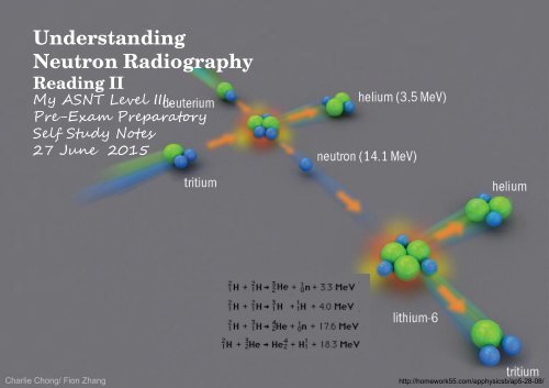
• The low-voltage type employing the reaction 3 H + 2 H → 4 He + 1 n , a(d,T)<br />
generator, where n, d, and T represent the neutron, deuteron (the nucleus<br />
<strong>of</strong> a deuterium atom, D or 2 H, that consists <strong>of</strong> one neutron and one proton),<br />
and tritium ( 3 H), respectively<br />
• High-energy x-ray machines, in which (x,n) reactions are used, where x<br />
represents x-ray radiation<br />
• Van de Graaff accelerators<br />
• More recently, high-energy linear accelerators and cyclotrons to generate<br />
neutrons by charged-particle reactions on beryllium or lithium targets<br />
Charlie Chong/ Fion Zhang
■ Low-Voltage Accelerators. A (d,T) generator provides fast-neutron<br />
yields in the range <strong>of</strong> 10 10 to 10 12 n/s. Target lives in sealed neutron tubes are<br />
reasonable (100 to 1000 h, depending on yield), and the sealed-tube system<br />
presents a source similar to that <strong>of</strong> certain types <strong>of</strong> x-ray machines.<br />
■ High- nergy X-Ray Machines. An (x,n) neutron source is a high-energy<br />
x-ray source such as a linear accelerator that can be converted for the<br />
production <strong>of</strong> neutrons by adding a suitable secondary target:<br />
for example, beryllium. X- ays having energies above an energy threshold<br />
level cause the secondary target to emit neutrons; in beryllium, the threshold<br />
x-ray energy for neutron production is 2.67 × 10 -13 J (1.66 MeV). Useful<br />
neutron radiography has been performed with an 8.8 × 10 -13 J (5.5 MeV)<br />
linear accelerator having an x-ray output <strong>of</strong> 0.17 C/kg · min (650 R/min) at 1<br />
m (3 ft). Changeover time from neutron emission to x-ray emission for this<br />
source was only 1 h. Beam intensities for neutron radiography with this<br />
source were about 5 × 10 4 n/cm 2 · s. with reasonable beam collimation.<br />
Charlie Chong/ Fion Zhang
■ Van de Graaff Accelerators.<br />
Much higher beam intensities have been obtained by the acceleration <strong>of</strong><br />
deuterons onto a beryllium target in a 3.2 × 10 -13 J (2.0 MeV) Van de Graaff<br />
generator. An intensity <strong>of</strong> 1.2 × 10 6 n/cm 2 · s was achieved (with medium<br />
collimation), and it is estimated that an acceleration voltage <strong>of</strong> 4.8 × 10 -13 J<br />
(3.0 MeV) would improve beam intensity by a factor <strong>of</strong> approximately six. The<br />
principle <strong>of</strong> the Van de Graaff machine is illustrated in Fig. 3. A rotating belt<br />
transports the charge from a supply to a high-voltage terminal. An ion source<br />
within the terminal is fed deuterium gas from a reservoir frequently located<br />
within the terminal. A radio-frequency system ionizes the gas, and positive<br />
ions are extracted into the accelerator tube. The terminal voltage <strong>of</strong> about 3<br />
MV is distributed by a resistor chain over about 80 gaps forming the<br />
accelerator tube, all <strong>of</strong> which is enclosed in a pressure vessel filled with<br />
insulating gas (N 2 and CO 2 at 2.0 MPa, or 290 psi).<br />
Charlie Chong/ Fion Zhang
Fig. 3 Cross section showing Van de Graaff principle as it is applied to<br />
neutron radiography. Source: Ref 6<br />
Charlie Chong/ Fion Zhang
The particle beam is extracted along flight tubes. In a typical neutron reaction,<br />
the beam bombards a water-cooled beryllium target in the center <strong>of</strong> the water<br />
moderator tank, which also serves as a partial shield. The higher-energy<br />
accelerators indicated above can provide neutron yields <strong>of</strong> 10 13 n/s and<br />
moderated, well-collimated beam intensities <strong>of</strong> the order <strong>of</strong> 10 6 n/cm 2 ·s.<br />
A few 4.8 × 10 -13 J (3.0 MeV) Van de Graaff generators have recently been<br />
placed in service for thermal-neutron radiography. In one such Van de Graaff<br />
system designed for neutron radiography, deuterons (4.8 × 10 -13 J, or 3 MeV;<br />
280 A) are accelerated onto a disk-shaped, water-cooled beryllium metal<br />
target. <strong>Neutron</strong>s in the range <strong>of</strong> 3.2 to 9.6 × 10 -13 J (2 to 6 MeV) are emitted<br />
preferentially in the forward direction and are moderated in water. The 4 (solid<br />
angle) yield <strong>of</strong> 5 × 10 11 n/s produces a peak thermal neutron flux <strong>of</strong> 2 × 10 9<br />
n/cm 2 · s. At a collimator ratio <strong>of</strong> 36:1, the typical exposure time for highquality<br />
film (3 × 10 9 n/cm 2 ) is about 2 h.<br />
Keywords:<br />
<strong>Neutron</strong> Yield<br />
Collimated beam intensity/ <strong>Neutron</strong> flux<br />
Charlie Chong/ Fion Zhang
The accelerator tank for the 4.8 × 10 -13 J (3 MeV) machine measures 5.2 m<br />
(17 ft) in length and 1.5 m (5 ft) in diameter. The weight is 6100 kg (13,500 lb).<br />
The dimensions <strong>of</strong> the water tank are approximately 1 m (3 ft) on each side.<br />
<strong>Neutron</strong> beams can be extracted through three horizontal beam collimators.<br />
Unlike reactors, subcritical multipliers, or (d, T) accelerators, the Van de<br />
Graaff accelerators utilize no radioactive source material and sometimes<br />
require less stringent license processes. Other acceleration machines or<br />
reactions can be used for thermal-neutron radiography. However, those<br />
described above have been most widely used.<br />
Charlie Chong/ Fion Zhang
3.3 Radioactive Sources.<br />
There are many possible radioactive sources. The characteristics <strong>of</strong> several<br />
radioisotopes that are commonly used are summarized in Table 3.<br />
Table 3 Properties and characteristics <strong>of</strong> several radioisotopes used for<br />
thermal-neutron radiography<br />
(γ, n)<br />
γ<br />
(α, n)<br />
γ<br />
(α, n)<br />
γ<br />
Charlie Chong/ Fion Zhang
Table 3 Properties and characteristics <strong>of</strong> several radioisotopes used for<br />
thermal-neutron radiography<br />
(α, n)<br />
(α, n)<br />
γ<br />
Charlie Chong/ Fion Zhang
■ Radioisotopes<br />
<strong>of</strong>fer the best prospect for a portable neutron-radiographic facility, but it<br />
should be recognized that the thermal-neutron intensity is only about 10 -5 <strong>of</strong><br />
the total fast-neutron yield from the source. Consequently, neutron<br />
radiography using a radioisotope as a neutron source normally requires long<br />
exposure times and fast films. For example, a typical 3.7 × 10 11 Bq (10 Ci)<br />
source would provide a total fast-neutron yield <strong>of</strong> the order <strong>of</strong> 10 7 n/s. The<br />
radiographic intensity would be about 10 2 n/cm 2 · s, and a typical exposure<br />
time using a fast film/converter-screen combination would be about 1 h.<br />
Californium-252, usually purchased in the form shown in Fig. 4, has been the<br />
most frequently used radioactive source for neutron radiography.<br />
Charlie Chong/ Fion Zhang
Fig. 4 Cross section <strong>of</strong> doubly encapsulated 252 Cf source. Source: Ref 6<br />
Charlie Chong/ Fion Zhang
3.4 Subcritical Assembly.<br />
Another type <strong>of</strong> source that has received some attention is a subcritical<br />
assembly. This type <strong>of</strong> source is similar to a reactor, except that the neutron<br />
flux is less and the design is such that criticality cannot be achieved. A<br />
subcritical assembly <strong>of</strong>fers some <strong>of</strong> the same neutron multiplication features<br />
as a reactor. It is somewhat easier to operate, and safety precautions are less<br />
stringent, because it is not capable <strong>of</strong> producing a self-sustaining neutron<br />
chain reaction.<br />
Interesting reading:<br />
https://en.wikipedia.org/wiki/Critical_mass<br />
Charlie Chong/ Fion Zhang
4.0 Attenuation <strong>of</strong> <strong>Neutron</strong> Beams<br />
Unlike electrons and electromagnetic radiation, which interact with orbital<br />
electrons surrounding an atomic nucleus, neutrons interact only with atomic<br />
nuclei. Usually, neutrons are deflected by interaction with the nuclei, but<br />
occasionally a neutron is absorbed into a nucleus. When a neutron collides<br />
with the nucleus <strong>of</strong> an atom and is merely deflected, the neutron imparts<br />
some <strong>of</strong> its kinetic energy to the atom. Both the neutron and the atom move<br />
<strong>of</strong>f in different directions from the original direction <strong>of</strong> motion <strong>of</strong> the neutron.<br />
This process, known as scattering, reduces the kinetic energy <strong>of</strong> the neutron<br />
and the probability that the neutron will pass through the object (testpiece) in<br />
a direction that will permit it to be detected by a device placed behind the<br />
object. True absorption <strong>of</strong> neutrons occurs when they are captured by nuclei.<br />
The capture <strong>of</strong> a neutron transforms the nucleus to the next-higher isotope <strong>of</strong><br />
the target nucleus and sometimes produces an unstable nucleus that then<br />
undergoes radioactive decay.<br />
Charlie Chong/ Fion Zhang
The probability that a collision between a neutron and a nucleus will result in<br />
capture is known as the capture cross section and is expressed as an<br />
effective area per atom. (The capture cross section is usually measured in<br />
barns, 1 barn equaling 10 -24 cm 2 or 1.6 × 10 -5 in. 2 .) The capture cross section<br />
varies with neutron energy, atomic number, and mass number. (the<br />
probability <strong>of</strong> neutron/ nuclei collision that results in capture)<br />
For thermal neutrons (energy <strong>of</strong> about 4.0 × 10 -21 J, or 0.025 eV), the<br />
average capture cross section varies randomly with atomic number, being<br />
high for certain elements and relatively low for other elements. The cross<br />
section actually varies by isotope rather than element. However,<br />
radiographers usually consider an average cross section for an element. For<br />
intermediate neutrons (energies <strong>of</strong> 8.0 × 10 -20 to 1.6 × 10 -15 J, or 0.5 eV to<br />
10 keV) and for fast neutrons (energies exceeding 1.6 × 10 -15 J, or 10 keV),<br />
the capture cross section is normally smaller than that for thermal neutrons,<br />
and there is much less variation with atomic number.<br />
For fast neutrons, most elements are similarly absorbing, and scattering is the<br />
dominant process <strong>of</strong> attenuation.<br />
Charlie Chong/ Fion Zhang
In relation to other types <strong>of</strong> penetrating radiation, many materials interact less<br />
with neutrons. Therefore, neutrons can sometimes be used to inspect greater<br />
thicknesses than can be conveniently inspected with electromagnetic<br />
radiation. The combined effect <strong>of</strong> scattering and capture can be expressed as<br />
a mass-absorption coefficient; this coefficient is used to determine the<br />
exposure factor for the neutron radiography <strong>of</strong> a given object (testpiece). For<br />
a given material, attenuation varies exponentially with thickness, and the<br />
basic law <strong>of</strong> radiation absorption (discussed in the article "Radiographic<br />
Inspection" in this Volume) applies to neutron attenuation as well as to the<br />
attenuation <strong>of</strong> electromagnetic radiation.<br />
μ = (ρN/A)∙σ<br />
I = I o e -μt<br />
Charlie Chong/ Fion Zhang
5.0 <strong>Neutron</strong> Detection Methods<br />
Detection methods for neutron radiography generally use photographic or x-<br />
ray films. In the so-called direct-exposure method, film is exposed directly to<br />
the neutron beam, with a conversion screen or intensifying screen providing<br />
the secondary radiation that actually exposes the film (Fig. 5a).<br />
Alternatively, film can be used to record an autoradiographic image from a<br />
radioactive image-carrying screen in a technique called the transfer method<br />
(Fig. 5b).<br />
Charlie Chong/ Fion Zhang
Fig. 5 Schematics <strong>of</strong> neutron radiography with film using the direct-exposure<br />
method (a) and the transfer method (b). The cassette is a light-tight device for<br />
holding film or conversion screens and film in close contact during exposure.<br />
Charlie Chong/ Fion Zhang
5.1 Direct-Exposure Method.<br />
Conversion screens <strong>of</strong> thin gadolinium foil or a scintillator have been most<br />
widely used in the direct-exposure method. When bombarded with a beam <strong>of</strong><br />
neutrons, some <strong>of</strong> the gadolinium atoms absorb some <strong>of</strong> the neutrons and<br />
then promptly emit γ-rays. The γ-rays in turn produce internal conversion<br />
electrons that actually expose the film; these are directly related in intensity to<br />
the intensity <strong>of</strong> the neutron beam. Scintillators, on the other hand, are<br />
fluorescent materials <strong>of</strong>ten made <strong>of</strong> zinc sulfide crystals that also contain a<br />
specific isotope, such as 6 Li 3 or 10 B 5 . In a neutron beam, these isotopes react<br />
with neutrons as follows:<br />
6<br />
Li 3 + 1 n 0 → 3 H 1 + α ( 4 He 2 )<br />
10<br />
B 5 + 1 n 0 → 7 Li 3 + α ( 4 He 2 )<br />
Charlie Chong/ Fion Zhang
The α particles emitted as a result <strong>of</strong> these reactions cause the zinc sulfide to<br />
fluoresce, which in turn exposes the film. Gadolinium oxysulfide, a scintillator<br />
originally developed for conventional radiography, is now widely used for<br />
neutron radiography. Scintillators provide useful images with total exposures<br />
as low as 5 × 10 5 n/cm 2 . The high speed and favorable relative<br />
neutron/gamma response <strong>of</strong> scintillators make them attractive for use with<br />
nonreactor neutron sources. For high-intensity sources, gadolinium screens<br />
are widely used. Gadolinium screens provide greater uniformity and image<br />
sharpness (high contrast resolution <strong>of</strong> 10 μm, or 400 μin., has been reported),<br />
but an exposure about 30 or more times that <strong>of</strong> a scintillator is required, even<br />
with fast films. Excessive background radiation should be kept to a minimum<br />
because it can have a detrimental effect on image quality.<br />
Keywords:<br />
Zinc Sulfide-Scintillator<br />
Gadolinium oxysulfide-Scintillator<br />
Gadolinium screens-Non Scintillator<br />
Charlie Chong/ Fion Zhang
5.2 In the transfer method,<br />
a thin sheet <strong>of</strong> metal called a transfer screen, which is usually made <strong>of</strong> indium<br />
or dysprosium, is exposed to the neutron beam transmitted through the<br />
specimen. <strong>Neutron</strong> capture by the isotope 115 In 49 or 164 Dy 66 (Dysprosium)<br />
induces radioactivity, indium having a half-life <strong>of</strong> 54 min and dysprosium a<br />
half-life <strong>of</strong> 2.35 h. The intensity <strong>of</strong> radioactive emission from each area <strong>of</strong> the<br />
transfer screen is directly related to the intensity <strong>of</strong> the portion <strong>of</strong> the<br />
transmitted neutron beam that induced radioactivity in that area. The<br />
radiograph to be interpreted is made by placing the radioactive transfer<br />
screen in contact with a sheet <strong>of</strong> film. The particle β and γ-ray emissions from<br />
the transfer screen expose the film, with film density in various portions <strong>of</strong> the<br />
developed image being proportionally related to the intensity <strong>of</strong> radioactive<br />
emission.<br />
Keywords:<br />
Transfer screen-indium or dysprosium, In, Dy.<br />
Thermal neutron filter using Cadmium for epithermal neutron radiography, Cd.<br />
Converter screen uses gadolinium which emit beta particles, Gd.<br />
Charlie Chong/ Fion Zhang
The transfer method is especially valuable for inspecting a radioactive<br />
specimen. Although the radiation emitted by the specimen (especially γ-rays)<br />
causes heavy film fogging during conventional radiography or direct-exposure<br />
neutron radiography, the same radiation will not induce radioactivity in a<br />
transfer screen. Therefore, a clear image <strong>of</strong> the specimen can be obtained<br />
even when there is a high level <strong>of</strong> background radiation. In comparing the two<br />
primary detection methods, the direct-exposure method <strong>of</strong>fers high speed,<br />
unlimited image integration time, and the best spatial resolution.<br />
The transfer method <strong>of</strong>fers insensitivity to the γ-rays emitted by the specimen<br />
and greater contrast because <strong>of</strong> lower amounts <strong>of</strong> scattered and secondary<br />
radiation.<br />
Keypoints:<br />
Direct Method: Best spatial resolution<br />
Transfer Method; Greater contrast<br />
Charlie Chong/ Fion Zhang
The direct-exposure method <strong>of</strong>fers:<br />
• high speed,<br />
• unlimited image integration time, and<br />
• the best spatial resolution.(?)<br />
The transfer method <strong>of</strong>fers:<br />
• insensitivity to the γ-rays emitted by the specimen and<br />
• greater contrast because <strong>of</strong> lower amounts <strong>of</strong> scattered and secondary<br />
radiation.<br />
Charlie Chong/ Fion Zhang
5.3 Real-time imaging,<br />
in which light from a scintillator is observed by a television camera, can also<br />
be used for neutron radiography. Because <strong>of</strong> low brightness, most real-time<br />
neutron radiographic images are enhanced by an image-intensifier tube,<br />
which may be separate or integral with the scintillator screen. This method<br />
can be used for such applications as the study <strong>of</strong> fluid flow in a closed system<br />
or the study <strong>of</strong> metal flow in a mold during casting. The lubricants moving in<br />
an operating engine have been observed with the real-time neutron imaging<br />
method.<br />
Charlie Chong/ Fion Zhang
Real Time <strong>Radiography</strong> Set-Up<br />
Charlie Chong/ Fion Zhang<br />
http://crisasantos.com.br/com/neutron-radiography
6.0 Applications<br />
Various applications concerning the inspection <strong>of</strong> ordnance 军 备 物 资 ,<br />
explosive, aerospace, and nuclear components. The presence, absence, or<br />
correct placement <strong>of</strong> explosives, adhesives, O- ings, plastic components, and<br />
similar materials can be verified. Nuclear fuel and control materials can be<br />
inspected to determine the distribution <strong>of</strong> isotopes and to detect foreign or<br />
imperfect material. Ceramic residual core in investment cast turbine blades<br />
can be detected. Observations <strong>of</strong> corrosion in metal assemblies are possible<br />
because <strong>of</strong> the excellent neutron sensitivity to the hydrogenous corrosion<br />
product. Hydride deposition in metals and diffusion <strong>of</strong> boron in heat treated<br />
boron-fiber composites can be observed. The following examples illustrate<br />
the application <strong>of</strong> neutron radiography to the inspection <strong>of</strong> radioactive<br />
materials and several assemblies <strong>of</strong> metallic and nonmetallic components.<br />
Charlie Chong/ Fion Zhang
Example 1: Thermal-<strong>Neutron</strong> <strong>Radiography</strong> Used to Determine Size <strong>of</strong><br />
Highly Radioactive Nuclear Fuel Elements.<br />
Highly radioactive nuclear fuel elements required size measurements to<br />
determine the extent <strong>of</strong> dimensional changes that may have occurred during<br />
irradiation. Generally, inspection is done in a hot cell, but because hot-cell<br />
inspection is a relatively long, tedious, and costly procedure, neutron<br />
radiography was selected. The fuel elements to be inspected consisted <strong>of</strong> 6.4<br />
mm ( ¼ in.) diam cylindrical pellets <strong>of</strong> UO 2 -PuO 2 ; the plutonium content was<br />
20%, and the uranium was enriched in 235 U. The pellets had been irradiated<br />
to 10% burnup, which resulted in a level <strong>of</strong> radioactivity <strong>of</strong> 3 × 10 -2 Ci/kg∙h<br />
(10 KR/h) at 0.3 m (1 ft). Five elements were selected for inspection. A<br />
neutron radiograph was taken by activating 0.25 mm (0.010 in.) thick<br />
dysprosium foil with a transmitted beam <strong>of</strong> thermal neutrons.<br />
An autoradiograph <strong>of</strong> the activated-dysprosium transfer screen on a mediumpeed<br />
x-ray film yielded the result shown in the positive print in Fig. 6.<br />
Charlie Chong/ Fion Zhang
Both 235U and plutonium have high attenuation coefficients for thermal<br />
neutrons. The high contrast <strong>of</strong> the fuel pellets made it possible to measure<br />
pellet diameter directly from the neutron radiographs. These measurements<br />
were both repeatable and statistically significant within 0.013 mm (0.0005 in.).<br />
Later, radiographic measurements were compared with physical<br />
measurements made in a hot cell. The two sets <strong>of</strong> values corresponded within<br />
0.038 mm (0.0015 in.).<br />
Charlie Chong/ Fion Zhang
Fig. 6 Positive print <strong>of</strong> a thermal-neutron radiograph <strong>of</strong> five irradiated nuclear<br />
fuel elements, taken to determine if dimensional changes occurred during<br />
irradiation. Radiograph was made using a dysprosium transfer-screen<br />
method. Dark squares in middle element are voids.<br />
voids.<br />
Rods<br />
Charlie Chong/ Fion Zhang
Example 2: Indium-Resonance Technique for Determining Internal<br />
Details <strong>of</strong> Highly Radioactive Nuclear Fuel Elements.<br />
The five nuclear fuel elements inspected for dimensional changes in Example<br />
1 were further inspected for internal details. This was necessary because the<br />
thermal-neutron inspection procedure did not reveal any internal details; it<br />
only shadowed the pellets, as shown by the positive print in Fig. 6. To inspect<br />
for internal details, an indium-resonance technique, which utilizes epithermal<br />
neutrons, was used.<br />
In this technique, a collimated neutron beam was filtered by 0.5 mm (0.02 in.)<br />
<strong>of</strong> cadmium to remove most <strong>of</strong> the thermal neutrons. Filtering produced a<br />
neutron beam with a nominal average energy somewhat above thermal. The<br />
epithermal neutron beam passed through the fuel elements and activated a<br />
sheet <strong>of</strong> indium foil. <strong>Neutron</strong>s with an energy <strong>of</strong> about 2.34×10 -19 J (1.46 eV),<br />
which is the resonance-absorption energy for indium (not the object!) , were<br />
primarily involved in activation.<br />
Comments: Indium-Resonance Technique is a type <strong>of</strong> transfer technique.<br />
Charlie Chong/ Fion Zhang
The positive print <strong>of</strong> a radiograph made with epithermal neutrons shown in<br />
Fig. 7 reveals considerable internal details, in contrast to the lack <strong>of</strong> internal<br />
details in Fig. 6. With epithermal neutrons, there was less attenuation by the<br />
fuel elements than with thermal neutrons. Therefore, internal details that were<br />
not revealed by thermal neutron radiography: such as cracking or chipping <strong>of</strong><br />
fuel pellets, and dimensional features <strong>of</strong> the central void in the fuel pellets<br />
(including changes in size and accumulation <strong>of</strong> fission products)- were<br />
revealed with the indium-resonance technique.<br />
Charlie Chong/ Fion Zhang
Fig. 7 Positive print <strong>of</strong> a neutron radiograph <strong>of</strong> the same five nuclear fuel<br />
elements shown in Fig. 6. Radiograph was made with epithermal neutrons<br />
and an indium-resonance technique, and it reveals internal details not shown<br />
in the thermal-neutron radiograph in Fig. 6<br />
Charlie Chong/ Fion Zhang
Example 3: Use <strong>of</strong> Conventional and <strong>Neutron</strong> <strong>Radiography</strong> to Inspect an<br />
Explosive Device for Correct Assembly.<br />
Small explosive devices assembled from both metallic and nonmetallic<br />
components required inspection to ensure correct assembly. The explosive<br />
and the components made <strong>of</strong> paper, plastic, or other low atomic number<br />
materials, which are less transparent to thermal neutrons than to x-rays, could<br />
be readily observed with thermal-neutron radiography. Metallic components<br />
were inspected by conventional x-ray radiography. A positive print <strong>of</strong> a<br />
thermal-neutron, direct-exposure radiograph <strong>of</strong> a 50 mm (2 in.) long explosive<br />
device is shown in Fig. 8(a). The radiograph was made on Industrex R film<br />
(Eastman Kodak), using a gadolinium-foil screen. Total exposure was 3 ×<br />
10 9 n/cm 2 , which was achieved with an exposure time <strong>of</strong> 4 to 5 min.<br />
Charlie Chong/ Fion Zhang
At the top in Fig. 8(a), just inside the stainless steel cap, can be seen a line<br />
image that corresponds to a moisture absorbent made <strong>of</strong> chemically treated<br />
paper. Below the paper is a mottled image, which is the explosive charge.<br />
Below the explosive charge are plastic components and, at the very bottom,<br />
epoxy. A conventional radiograph <strong>of</strong> the same device is shown in Fig. 8(b).<br />
The metallic components, which were poorly delineated in the thermalneutron<br />
radiograph, are more clearly seen in Fig. 8(b). Together, the two<br />
radiographs verified that both metallic and nonmetallic components were<br />
correctly assembled.<br />
Charlie Chong/ Fion Zhang
Fig. 8 Comparison <strong>of</strong> positive prints <strong>of</strong> a thermal-neutron radiograph (a) and a<br />
conventional radiograph (b) <strong>of</strong> a 50 mm (2 in.) long explosive device. <strong>Neutron</strong><br />
radiograph reveals details <strong>of</strong> paper, explosive compound, and plastic<br />
components not revealed by x-rays.<br />
Charlie Chong/ Fion Zhang
Example 4: Use <strong>of</strong> <strong>Neutron</strong> <strong>Radiography</strong> to Detect Corrosion in Aircraft<br />
Components.<br />
Aluminum honeycomb components are extensively used for aircraft<br />
construction. The aluminum material is subject to corrosion if exposed to<br />
water or humid environments. Thermal-neutron radiography is an excellent<br />
method <strong>of</strong> detecting hidden corrosion in these assemblies. The corrosion<br />
products are typically hydroxides or water-containing oxides; these corrosion<br />
products contain hydrogen, a material that strongly attenuates thermal<br />
neutrons. The aluminum metal, on the other hand, is essentially transparent<br />
to the neutrons. Therefore, a thermal-neutron radiograph <strong>of</strong> a corroded<br />
aluminum honeycomb assembly shows the corrosion product and other<br />
attenuating components such as adhesives and sealants. Figure 9 depicts a<br />
thermal-neutron radiograph <strong>of</strong> an aluminum honeycomb assembly showing<br />
the beginnings <strong>of</strong> corrosion.<br />
Charlie Chong/ Fion Zhang
The white line image the middle <strong>of</strong> the radiograph represents the adhesive<br />
coupling together two core sections. The faint white smears in the upper half<br />
<strong>of</strong> the image and the double dot in the lower left area are images <strong>of</strong> corrosion<br />
as disclosed by the thermal-neutron radiograph. Developmental work has<br />
shown that thermal-neutron imaging techniques are capable <strong>of</strong> detecting the<br />
corrosion product buildup represented by an aluminum metal loss <strong>of</strong> 25 μm<br />
(1000 μin.). The neutron method, therefore, is a very sensitive technique for<br />
the detection <strong>of</strong> corrosion.<br />
adhesive coupling<br />
corrosion<br />
Charlie Chong/ Fion Zhang
Fig. 9 Thermal-neutron radiograph <strong>of</strong> aluminum honeycomb aircraft<br />
component showing early evidence <strong>of</strong> hydrogen corrosion. See text for<br />
discussion. Courtesy <strong>of</strong> D. Froom, U.S. Air Force, McClellan Air Force Base<br />
Charlie Chong/ Fion Zhang
Example 5: Use <strong>of</strong> <strong>Neutron</strong> <strong>Radiography</strong> to Detect Corrosion in<br />
Adhesive - Bonded Aluminum Honeycomb Structures.<br />
Aluminum corrosion <strong>of</strong> aircraft surfaces has plagued both military and civilian<br />
aircraft. Identification <strong>of</strong> this corrosion has been difficult, at best, usually being<br />
detected after the corrosion has caused the part to fail. Of the nondestructive<br />
testing methods used to detect aluminum corrosion, thermal neutron<br />
radiography has proved the most sensitive method to date. The detection <strong>of</strong><br />
aluminum corrosion is based on the attenuation properties <strong>of</strong> hydrogen<br />
associated with the corrosion products rather than aluminum and aluminum<br />
oxide with their low attenuation coefficients. Depending on the environment,<br />
the corrosion products include aluminum trihydrates, monohydrates, and<br />
various other aluminum salts. Because the linear attenuation coefficient for<br />
aluminum is similar to that <strong>of</strong> water and about 28 times greater than that for<br />
aluminum, a 0.13 mm (0.005 in.) corrosion layer should be detectable under<br />
optimum conditions.<br />
Charlie Chong/ Fion Zhang
The sensitivity standard plate for aluminum corrosion fabricated by the<br />
Aeronautical Research Laboratories (Australia) contains corrosion products<br />
varying from 0.13 to 0.61 mm (0.005 to 0.024 in.) thick (Fig. 10). Aluminum<br />
corrosion <strong>of</strong> honeycomb structures is complicated by the bonding adhesives<br />
that may appear similar in a neutron radiograph (Fig. 11a) (see the article<br />
"Adhesive-Bonded Joints" in this Volume). Tilting <strong>of</strong> the honeycomb structure<br />
will alleviate this problem by allowing adhesive found along the bond lines to<br />
be distinguished from the randomly distributed corrosion products (Fig. 11b).<br />
Charlie Chong/ Fion Zhang
Fig. 10 Standard plate for aluminum corrosion detection contains 0.13 to 0.61<br />
mm (0.005 to 0.024 in.) thick corrosion products. Courtesy <strong>of</strong> R. Tsukimura,<br />
Aerotest Operations Inc.<br />
Charlie Chong/ Fion Zhang
Fig. 11 Effect <strong>of</strong> bonding adhesives on the quality <strong>of</strong> neutron radiographs<br />
obtained when checking for aluminum corrosion in honeycomb structures.<br />
Radiograph taken (a) normal to specimen surface and (b) tilted at any angle<br />
other than 90° to specimen surface. Courtesy <strong>of</strong> R. Tsukimura, Aerotest<br />
Operations Inc.<br />
Charlie Chong/ Fion Zhang
Example 6: Use <strong>of</strong> <strong>Neutron</strong> <strong>Radiography</strong> to Verify Welding <strong>of</strong> Dissimilar<br />
<strong>Materials</strong> (Titanium and Niobium).<br />
Exotic metal welded joints are a product <strong>of</strong> the extremely cold environment <strong>of</strong><br />
space and man's desire to explore the vast emptiness <strong>of</strong> space. For space<br />
vehicles, attitude control rockets provide the fine touch for proper vehicle<br />
alignment.<br />
For one application, a titanium-niobium welded joint was required between<br />
the light-weight propellant tank and the nozzle section. Attempts to verify weld<br />
integrity using conventional radiography were not productive. Thermal<br />
neutron radiography provided the image required to ensure quality welds.<br />
This defect standard weld shows the porosity at the seam and the similar<br />
thermal neutron attenuation for both titanium (Ti) and niobium (formerly<br />
known as columbium, Cb) (Fig. 12a). For comparison, the x-ray radiograph<br />
image is also shown (Fig. 12b).<br />
Charlie Chong/ Fion Zhang
Fig. 12 Comparison <strong>of</strong> thermal neutron (a) and x-ray (b) radiographs <strong>of</strong> a<br />
titanium-niobium welded joint. Courtesy <strong>of</strong> R. Tsukimura, Aerotest Operations<br />
Inc.<br />
Charlie Chong/ Fion Zhang
Example 7: Use <strong>of</strong> <strong>Neutron</strong> <strong>Radiography</strong> to Detect Core Material Still<br />
Remaining in the Interior Cooling Passages <strong>of</strong> Air-Cooled Turbine<br />
Blades.<br />
Investment casting <strong>of</strong> turbine blades using the lost wax process results in<br />
relatively clean castings. As the demand for higher-powered turbine engines<br />
has increased, the interior cooling passages for air-cooled turbine blades<br />
have become more and more complex. Concurrently, the removal <strong>of</strong> the core<br />
material has become increasingly more difficult. Incomplete removal <strong>of</strong> the<br />
core results in restricted flow through the cooling passages and possible<br />
failure <strong>of</strong> the overheated blade.<br />
Previously, visual inspection was the nondestructive inspection method <strong>of</strong><br />
choice for residual core detection. However, current designs preclude the use<br />
<strong>of</strong> borescopes and other visual means for the interior passages. X-<br />
adiography has proved rather ineffective in detecting residual core material.<br />
Thermal neutron radiography is the nondestructive testing method <strong>of</strong> choice,<br />
especially when gadolinium oxide (Gd 2 O 3 ) is used to dope the core material<br />
(1 to 3% by weight) (Fig. 13) prior to casting the blade.<br />
Charlie Chong/ Fion Zhang
When concerns about the possible detrimental effects <strong>of</strong> Gd 2 O 3 during the<br />
casting process prevents its use in the core material, a procedure was<br />
developed to tag the residual core material after the core removal process.<br />
The castings are dipped in a gadolinium solution [Gd(NO 3 ) 2 in solution] to<br />
impregnate any residual core, which is then imaged and subsequently<br />
detected by neutron radiography. The blades shown in Fig. 14 have been<br />
tagged. The neutron radiograph shows any residual core material greater<br />
than 0.38 mm (0.015 in.) in diameter. Figure 15 is a schematic <strong>of</strong> typical core<br />
fragments in investment cast turbine blades detected by thermal neutron<br />
radiography. Image clarity <strong>of</strong> gadolinium tagged or doped cores is much<br />
greater than that <strong>of</strong> normal cores.<br />
Charlie Chong/ Fion Zhang
Fig. 13 Residual core material in a gas-cooled aircraft-engine turbine blade<br />
as detected by thermal neutron radiography. The excess core material,<br />
tagged with 1.5% Gd 2 O 3 , is shown circled in the second photo from the right.<br />
Courtesy <strong>of</strong> R. Tsukimura, Aerotest Operations Inc.<br />
Charlie Chong/ Fion Zhang
Fig. 14 Thermal neutron radiograph <strong>of</strong> 12 turbine blades tagged with Gd 2<br />
O 3<br />
solution.<br />
One <strong>of</strong> the 12 blades (located in the top row and second from the left) contains<br />
residual core material in its upper right-hand corner cooling passage. Courtesy <strong>of</strong> R.<br />
Tsukimura, Aerotest Operations Inc.<br />
Charlie Chong/ Fion Zhang
Fig. 15 Schematic <strong>of</strong> turbine blade core standards: gadolinium [Gd(NO 3 ) 3 in<br />
solution] tagged core, normal core (no gadolinium tagging or doping), and<br />
Gd 2 O 3 doped core. Typical core fragments <strong>of</strong> various thicknesses are shown.<br />
Source: R. Tsukimura, Aerotest Operations Inc.<br />
Charlie Chong/ Fion Zhang
Charlie Chong/ Fion Zhang
Example 8: Use <strong>of</strong> <strong>Neutron</strong> <strong>Radiography</strong> to Verify Position <strong>of</strong> Explosive<br />
Charges and Seating <strong>of</strong> O-Ring Seals in Explosive Bolt Assemblies.<br />
There are many critical applications <strong>of</strong> explosive release devices in aircraft,<br />
space, and missile systems. Nondestructive testing is an important step in the<br />
quality control portion <strong>of</strong> the production cycle for these units.<br />
Thermal neutron radiography has proved an indispensable tool in the<br />
nondestructive testing arsenal, particularly for thick-walled, metal devices,<br />
such as explosive bolts (Fig. 16). The inner details <strong>of</strong> explosive bolts can be<br />
imaged only by thermal neutron radiography methods (Fig. 17). This<br />
particular type <strong>of</strong> bolt from a missile system is activated from the bottom by<br />
actuating the firing pin onto the primer. The short section <strong>of</strong> mild detonating<br />
cord carries the energy to the output charge, which fractures the bolt and<br />
allows the bolt to be severed. In addition to the explosive charges, the internal<br />
O-ring seals, including the concentric pair around the firing pin and for the<br />
body are readily visible. For safety's sake, determining the presence <strong>of</strong> the<br />
shear pin can also be accomplished through the use <strong>of</strong> thermal neutron<br />
radiography.<br />
Charlie Chong/ Fion Zhang
Fig. 16 Schematic showing location <strong>of</strong> critical components that comprise an<br />
explosive bolt. Source: R. Tsukimura, Aerotest Operations Inc.<br />
Charlie Chong/ Fion Zhang
Fig. 17 Thermal neutron radiograph showing two sample bolts identical to the<br />
workpiece shown schematically in Fig. 16. Courtesy <strong>of</strong> R. Tsukimura,<br />
Aerotest Operations Inc.<br />
Charlie Chong/ Fion Zhang
Example 9: Application <strong>of</strong> <strong>Neutron</strong> <strong>Radiography</strong> to Determine Potting<br />
Fill Levels in Encapsulated Electronic Filters.<br />
Electronic filters are an integral component <strong>of</strong> all space and satellite systems.<br />
Because the cost <strong>of</strong> these satellites is very high and the cost to repair them<br />
even more prohibitive, high reliability filters are necessary. A common mode<br />
<strong>of</strong> filter failure is that caused by inadequate potting <strong>of</strong> the internal components<br />
and the subsequent physical breakdown <strong>of</strong> the filter during periods <strong>of</strong> high<br />
vibration, such as that encountered during vehicle launch. Thermal neutron<br />
radiography is the method <strong>of</strong> choice for determining potting fill levels in<br />
encapsulated filters. The potting material attenuates the thermal neutrons and<br />
appears as the light density area. Voids in the potting material, the fill level,<br />
and the distribution can readily be detected with neutron radiography.<br />
Charlie Chong/ Fion Zhang
Applications <strong>of</strong> <strong>Neutron</strong> Imaging in Earth Sciences and Biosciences<br />
2D & 3D <strong>Neutron</strong> radiography & Tomography<br />
Non-destructive imaging techniques are extremely powerful diagnostic tools in the<br />
study <strong>of</strong> internal structures without the need to break open the test sample. The<br />
requirement <strong>of</strong> non-destructive testing chiefly has two sources; the specimen may be<br />
rare or even unique (e.g. geological and archaeological artefacts), or breaking may<br />
defeat the purpose <strong>of</strong> the investigation (e.g. bonding between surfaces and internal<br />
fluid flows).<br />
The analytical information provided by neutron radiography (2-D) and tomography (3-<br />
D) are entirely complementary to their better-known x-ray and gamma-ray<br />
counterparts, but have important advantages; in particular, neutrons can penetrate<br />
many materials, including metals, relatively easily, whilst being highly sensitive to<br />
hydrogen. This has lead to application in fields as wide-ranging as archaeology,<br />
engineering, biomaterials, biology and earth sciences.<br />
Neutrograph at the ILL exploits the most intense neutron beam in world in use for this<br />
technique, giving it the highest time resolution. In the case <strong>of</strong> radiography, fast<br />
processes can be resolved below 1 ms, while 3-D tomographic imaging can be carried<br />
out in 10 s. Neutrograph is also highly sensitive in distinguishing between low<br />
contrasting materials. Currently, the spatial resolution is ~150 microns, but it is<br />
foreseen that this will improve in the near future.<br />
Charlie Chong/ Fion Zhang<br />
http://see.leeds.ac.uk/ebi/studentship-neutron.htm
Real Time Imaging: Combustion Chamber<br />
Charlie Chong/ Fion Zhang<br />
http://see.leeds.ac.uk/ebi/studentship-neutron.htm
Tomography <strong>of</strong> Antarctic Conifer Fossils<br />
3-D tomographic reconstruction <strong>of</strong> a late Early Eocene age conifer fossil (~53 million years old),<br />
discovered on Seymour Island, West Antarctica reveals a beautifully preserved new flora,<br />
Araucariaceae, much resembling Araucaria araucana, the modern-day Monkey Puzzle tree. In<br />
this case, neutron tomography has replaced the time-consuming and utterly destructive serial<br />
thin-sections method. The 3-D structure has been held in tact with the leaves spiraling around a<br />
central woody stem.<br />
Charlie Chong/ Fion Zhang<br />
http://see.leeds.ac.uk/ebi/studentship-neutron.htm
Dynamic <strong>Radiography</strong> <strong>of</strong> Fluid Flow Through Sandstone<br />
In situ 2-D dynamic radiographic imaging <strong>of</strong> consecutive fluid flows through<br />
an initially water-saturated cylindrical sandstone core, Ф 5cm. Internal<br />
structures and fault zones are clearly visible, and appear to behave quite<br />
differently for different fluid combinations.<br />
nitrogen-water<br />
oil-water<br />
Charlie Chong/ Fion Zhang<br />
water-nitrogen<br />
water-oil<br />
http://see.leeds.ac.uk/ebi/studentship-neutron.htm
<strong>Neutron</strong> graph<br />
Charlie Chong/ Fion Zhang<br />
http://crisasantos.com.br/com/neutron-radiography
<strong>Neutron</strong> graph<br />
Charlie Chong/ Fion Zhang<br />
http://crisasantos.com.br/com/neutron-radiography
End Of <strong>Reading</strong><br />
Charlie Chong/ Fion Zhang
<strong>Reading</strong>-3<br />
E1316<br />
Charlie Chong/ Fion Zhang
E1316 Section H: <strong>Neutron</strong> Radiologic Testing (NRT) Terms<br />
The terms defined in Section H are the direct responsibility <strong>of</strong> Subcommittee<br />
E07.05 on the Radiology (<strong>Neutron</strong>) Method. Additional radiological terms can<br />
be found in Section D.<br />
activation - the process <strong>of</strong> causing a substance to become artificially<br />
radioactive by subjecting it to bombardment by neutrons or other particles.<br />
attenuation coefficient - related to the rate <strong>of</strong> change in the intensity <strong>of</strong> a<br />
beam <strong>of</strong> radiation as it passes through matter. (See linear and mass<br />
attenuation coefficient.)<br />
attenuation cross section - the probability, expressed in barns, that<br />
a neutron will be totally absorbed by the atomic nucleus.<br />
barn - a unit <strong>of</strong> area used for expressing the area <strong>of</strong> nuclear cross sections.<br />
1 barn = 10 -24 cm 2 (3)<br />
Charlie Chong/ Fion Zhang
cadmium ratio - the ratio <strong>of</strong> the neutron reaction rate measured with a given<br />
bare neutron detector to the reaction rate measured with an identical neutron<br />
detector enclosed by a particular cadmium cover and exposed in the same<br />
neutron field at the same or an equivalent spatial location.<br />
NOTE 27 - In practice, meaningful experimental values can be obtained in an<br />
isotropic neutron field by using a cadmium filter approximately 1 mm thick.<br />
Cassette - light-tight device for holding film or conversion screens and film<br />
in close contact during exposure.<br />
contrast agent - a material added to a component to enhance details by<br />
selective absorption <strong>of</strong> the incident radiation.<br />
Charlie Chong/ Fion Zhang
conversion screen - a device that converts the imaged neutron beam to<br />
radiation or light that exposes the radiographic film.<br />
cross section -theapparent cross-sectional area <strong>of</strong> the nucleus as<br />
calculated on the basis <strong>of</strong> the probability <strong>of</strong> occurrence <strong>of</strong> a reaction by<br />
collision with a particle. It does not necessarily coincide with the geometrical<br />
cross-sectional area πr 2 . It is given in units <strong>of</strong> area, 1 barn = 10 −24 cm 2 .<br />
direct exposure imaging - in the direct exposure imaging method, the<br />
conversion screen and image recorder are simultaneously exposed to the<br />
neutron beam.<br />
electron volt - the kinetic energy gained by an electron after passing through<br />
a potential difference <strong>of</strong> 1 V.<br />
Charlie Chong/ Fion Zhang
facility scattered neutrons - neutrons scattered in the facility that contribute<br />
to the film exposure.<br />
γ - effective gamma content. γ is the percent background film darkening<br />
caused by low-energy photon radiation absorbed by pair production in 2 mm<br />
<strong>of</strong> lead.<br />
Charlie Chong/ Fion Zhang
Pair Production<br />
hν = E - + E + = (m 0 c 2 + K - ) + (m 0 c 2 + K + ) = K - + K + + 2m 0 c 2<br />
Charlie Chong/ Fion Zhang<br />
http://electrons.wikidot.com/pair-production-and-annihilation
gamma ray - electromagnetic radiation having its origin in an atomic nucleus.<br />
half-life T ½ - the time required for one half a given number <strong>of</strong> radioactive<br />
atoms to undergo decay.<br />
half-value layer - the thickness <strong>of</strong> an absorbing material required to reduce<br />
the intensity <strong>of</strong> a beam <strong>of</strong> incident radiation to one-half <strong>of</strong> its original intensity.<br />
image quality indicator - a device or combination <strong>of</strong> devices whose image or<br />
images on a neutron radiograph provide visual or quantitative data, or both,<br />
concerning the radiographic sensitivity <strong>of</strong> the particular neutron radiograph.<br />
Charlie Chong/ Fion Zhang
indirect exposure - a method in which only a gamma-insensitive conversion<br />
screen is exposed to the neutron beam. After exposure, the conversion<br />
screen is placed in contact with the image recorder.<br />
L/D ratio - one measure <strong>of</strong> the resolution capability <strong>of</strong> a neutron radiographic<br />
system. It is the ratio <strong>of</strong> the distance between the entrance aperture and the<br />
image plane (L) to the diameter <strong>of</strong> the entrance aperture (D).<br />
U g = Dt/L , I = Ф /[16∙(L/D) 2 ]<br />
Linear attenuation coefficient - a measure <strong>of</strong> the fractional decrease in<br />
radiation beam intensity per unit <strong>of</strong> distance traveled in the material (cm -1 ).<br />
low-energy photon radiation - Gamma- and X-ray photon radiation having<br />
energy less than 200 keV (0.2 Mev) (excluding visible and ultraviolet light).<br />
Charlie Chong/ Fion Zhang
mass attenuation coefficient - a measure <strong>of</strong> the fractional decrease in<br />
radiation beam intensity per unit <strong>of</strong> surface density cm 2 ∙gm −1 . (cm 2 ∙g -1 )<br />
Mass attenuation coefficient<br />
The mass attenuation coefficient or mass narrow beam attenuation coefficient<br />
<strong>of</strong> the volume <strong>of</strong> a material characterizes how easily it can be penetrated by a<br />
beam <strong>of</strong> light, sound, particles, or other energy or matter. In addition to visible<br />
light, mass attenuation coefficients can be defined for other electromagnetic<br />
radiation (such as X-rays), sound, or any other beam that attenuates. The SI<br />
unit <strong>of</strong> mass attenuation coefficient is the square meter per kilogram (m 2 /kg).<br />
Other common units include cm 2 /g (the most common unit for X-ray mass<br />
attenuation coefficients) and mL∙ g −1 ccm −1 (sometimes used in solution<br />
chemistry). "Mass extinction coefficient" is an old term for this quantity.<br />
The mass attenuation coefficient can be thought <strong>of</strong> as a variant <strong>of</strong> absorption<br />
cross section where the effective area is defined per unit mass instead <strong>of</strong> per<br />
particle.<br />
https://en.wikipedia.org/wiki/Mass_attenuation_coefficient<br />
Charlie Chong/ Fion Zhang
moderator - a material used to slow fast neutrons. <strong>Neutron</strong>s are slowed<br />
down when they collide with atoms <strong>of</strong> light elements such as hydrogen,<br />
deuterium, beryllium, and carbon.<br />
Why the<br />
heavier<br />
elements<br />
were not<br />
used as<br />
moderator?<br />
Charlie Chong/ Fion Zhang
NC - effective thermal neutron content or neutron radiographic contrast. NC is<br />
the percent background film exposure due to unscattered thermal neutrons.<br />
neutron - a neutral elementary particle having an atomic mass close to 1. In<br />
the free state outside <strong>of</strong> the nucleus, the neutron is unstable having a half-life<br />
<strong>of</strong> approximately 10 min. A neutron undergoes spontaneous beta decay to form a proton, a high<br />
energy electron (β particle) and an electron antineutrino. Whilst atomic and mass numbers are conserved in the<br />
process the combined mass <strong>of</strong> the products is slightly less than the original neutron mass. This accounts for the<br />
energy released. http://www.atnf.csiro.au/outreach//education/senior/cosmicengine/sun_nuclear.html<br />
http://scienceblogs.com/startswithabang/2013/07/0<br />
5/why-did-the-universe-start-<strong>of</strong>f-with-hydrogenhelium-and-not-much-else/<br />
Charlie Chong/ Fion Zhang
neutron radiography - the process <strong>of</strong> producing a radiograph using neutrons<br />
as the penetrating radiation.<br />
object scattered neutrons - neutrons scattered by the test objects that<br />
contribute to the film exposure.<br />
P - effective pair production content. P is the percent background exposure<br />
caused by pair production in 2 mm <strong>of</strong> lead.<br />
pair production - the process whereby a gamma photon with energy greater<br />
than 1.02 MeV is converted directly into matter in the form <strong>of</strong> an electronpositron<br />
pair. Subsequent annihilation <strong>of</strong> the positron results in the production<br />
<strong>of</strong> two 0.511 MeV gamma photons.<br />
process control radiograph - a radiograph which images a beam purity<br />
indicator and sensitivity indicator under identical exposure and processing<br />
procedures as the test object radiograph. A process control radiograph may<br />
be used to determine image quality parameters in circumstances <strong>of</strong> large or<br />
unusual test object geometry.<br />
Charlie Chong/ Fion Zhang
Pair Production<br />
hν = E - + E + = (m 0 c 2 + K - ) + (m 0 c 2 + K + ) = K - + K + + 2m 0 c 2<br />
Charlie Chong/ Fion Zhang<br />
http://electrons.wikidot.com/pair-production-and-annihilation
adiograph - a permanent, visible image on a recording medium produced by<br />
penetrating radiation passing through the material being tested.<br />
radiographic inspection - the use <strong>of</strong> X rays or nuclear radiation, or both, to<br />
detect discontinuities in material, and to present their images on a recording<br />
medium.<br />
radiography - the process <strong>of</strong> producing a radiograph using penetrating<br />
radiation.<br />
radiological examination - the use <strong>of</strong> penetrating ionizing radiation to<br />
display images for the detection <strong>of</strong> discontinuities or to help ensure integrity <strong>of</strong><br />
the part.<br />
Charlie Chong/ Fion Zhang
adiology - the science and application <strong>of</strong> X rays, gamma rays, neutrons, and<br />
other penetrating radiations.<br />
radioscopic inspection - the use <strong>of</strong> penetrating radiation and radioscopy to<br />
detect discontinuities in material.<br />
radioscopy - the electronic production <strong>of</strong> a radiological image that follows<br />
very closely the changes with time <strong>of</strong> the object being imaged.<br />
real-time radioscopy - radioscopy that is capable <strong>of</strong> following the motion <strong>of</strong><br />
the object without limitation <strong>of</strong> time.<br />
S - effective scattered neutron content. S is the percent background film<br />
darkening caused by scattered neutrons.<br />
scattered neutrons - neutrons that have undergone a scattering collision but<br />
still contribute to film exposure.<br />
Charlie Chong/ Fion Zhang
sensitivity value - the value determined by the smallest standard<br />
discontinuity in any given sensitivity indicator observable in the radiographic<br />
image. Values are defined by identification <strong>of</strong> type <strong>of</strong> indicator, size <strong>of</strong> defect,<br />
and the absorber thickness on which the discontinuity is observed.<br />
thermalization - the process <strong>of</strong> slowing neutron velocities by permitting the<br />
neutrons to come to thermal equilibrium with a moderating medium.<br />
thermalization factor - the inverse ratio <strong>of</strong> the thermal neutron flux obtained<br />
in a moderator, per source neutron.<br />
thermal neutrons - neutrons having energies ranging between 0.005 eV and<br />
0.5 eV; neutrons <strong>of</strong> these energies are produced by slowing down fast<br />
neutrons until they are in equilibrium with the moderating medium at a<br />
temperature near 20°C.<br />
Charlie Chong/ Fion Zhang
total cross section - the sum <strong>of</strong> the absorption and scattering cross sections.<br />
vacuum cassette - a light-tight device having a flexible entrance window,<br />
which when operated under a vacuum, holds the film and conversion screen<br />
in intimate contact during exposure.<br />
Charlie Chong/ Fion Zhang
Thermalization <strong>of</strong> <strong>Neutron</strong>s<br />
the last stage <strong>of</strong> the moderation <strong>of</strong> neutrons in various mediums, in which the<br />
role <strong>of</strong> chemical bonding and the thermal motion <strong>of</strong> the atoms <strong>of</strong> the medium<br />
become essential.<br />
When the kinetic energy <strong>of</strong> neutrons is reduced to values less than 1 electron<br />
volt, the neutron velocity becomes comparable to the velocity <strong>of</strong> thermal<br />
motion <strong>of</strong> atoms and molecules. Energy exchange arises between these<br />
species and the neutrons, leading to the establishment <strong>of</strong> an equilibrium<br />
Maxwellian velocity distribution <strong>of</strong> the neutrons. However, because <strong>of</strong> several<br />
factors, such as the motion and binding <strong>of</strong> atoms, absorption, and the finite<br />
size <strong>of</strong> the system, the energy spectra <strong>of</strong> neutrons in moderators differ from<br />
the equilibrium spectra. The study <strong>of</strong> the thermalization <strong>of</strong> neutrons is<br />
required for the calculation and prediction <strong>of</strong> the behavior <strong>of</strong> thermal reactors.<br />
Research in this area has been the source <strong>of</strong> new methods for the study <strong>of</strong><br />
the physics <strong>of</strong> solids and liquids.<br />
Charlie Chong/ Fion Zhang<br />
http://encyclopedia2.thefreedictionary.com/<strong>Neutron</strong>s%2c+Thermalization+<strong>of</strong>
<strong>Neutron</strong> temperature<br />
The neutron detection temperature, also called the neutron energy, indicates<br />
a free neutron's kinetic energy, usually given in electron volts. The term<br />
temperature is used, since hot, thermal and cold neutrons are moderated in a<br />
medium with a certain temperature. The neutron energy distribution is then<br />
adopted to the Maxwellian distribution known for thermal motion. Qualitatively,<br />
the higher the temperature, the higher the kinetic energy is <strong>of</strong> the free neutron.<br />
Kinetic energy, speed and wavelength <strong>of</strong> the neutron are related through the<br />
De Broglie relation.<br />
Charlie Chong/ Fion Zhang<br />
https://en.wikipedia.org/wiki/<strong>Neutron</strong>_temperature
Maxwellian distribution<br />
Charlie Chong/ Fion Zhang<br />
http://hyperphysics.phy-astr.gsu.edu/hbase/kinetic/kintem.html
<strong>Neutron</strong> energy distribution ranges<br />
<strong>Neutron</strong> energy range names<br />
But different ranges with different names<br />
are observed in other sources. For<br />
example, Epithermal neutrons have<br />
energies between 1 eV and 10 keV and<br />
smaller nuclear cross sections than<br />
thermal neutrons.<br />
Charlie Chong/ Fion Zhang<br />
https://en.wikipedia.org/wiki/<strong>Neutron</strong>_temperature
Thermal<br />
<strong>Neutron</strong>s in thermal equilibrium with their surroundings<br />
Most probable energy at 20 degrees (C) - 0.025 eV; Maxwellian distribution<br />
<strong>of</strong> 20 degrees (C) extends to about 0.2 eV.<br />
Epithermal<br />
<strong>Neutron</strong>s <strong>of</strong> energy greater than thermal<br />
Greater than 0.2 eV<br />
Cadmium<br />
<strong>Neutron</strong>s which are strongly absorbed by cadmium<br />
Less than 0.4 eV<br />
Epicadmium<br />
<strong>Neutron</strong>s which are not strongly absorbed by cadmium<br />
Greater than 0.6 eV<br />
Charlie Chong/ Fion Zhang<br />
https://en.wikipedia.org/wiki/<strong>Neutron</strong>_temperature
Slow<br />
<strong>Neutron</strong>s <strong>of</strong> energy slightly greater than thermal<br />
Less than 1 to 10 eV (sometimes up to 1 keV)<br />
Resonance<br />
In pile neutron physics, usually refers to neutrons which are strongly captured<br />
in the resonance <strong>of</strong> U-238, and <strong>of</strong> a few commonly used detectors (e.g.,<br />
Indium, Gold, etc.)<br />
1 eV to 300 eV<br />
Intermediate<br />
<strong>Neutron</strong>s that are between slow and fast<br />
Few hundred eV to 0.5 MeV<br />
Fast<br />
Greater than 0.5 MeV<br />
Charlie Chong/ Fion Zhang<br />
https://en.wikipedia.org/wiki/<strong>Neutron</strong>_temperature
Ultrafast<br />
Relativistic<br />
Greater than 20 MeV<br />
Pile<br />
<strong>Neutron</strong>s <strong>of</strong> all energies present in nuclear reactors<br />
0.001 eV to 15 MeV<br />
Fission<br />
<strong>Neutron</strong>s formed during fission<br />
100 keV to 15 MeV (Most probable: 0.8 MeV; Average: 2.0 MeV)<br />
Charlie Chong/ Fion Zhang<br />
https://en.wikipedia.org/wiki/<strong>Neutron</strong>_temperature
Ultracold neutrons (UCN)<br />
Ultracold neutrons are free neutrons which can be stored in traps made from<br />
certain materials.<br />
Charlie Chong/ Fion Zhang<br />
https://en.wikipedia.org/wiki/<strong>Neutron</strong>_temperature
Thermal neutrons<br />
A thermal neutron is a free neutron with a kinetic energy <strong>of</strong> about 0.025 eV<br />
(about 4.0×10 -21 J or 2.4 MJ/kg, hence a speed <strong>of</strong> 2.2 km/s), which is the<br />
energy corresponding to the most probable velocity at a temperature <strong>of</strong> 290 K<br />
(17 °C or 62 °F), the mode <strong>of</strong> the Maxwell–Boltzmann distribution for this<br />
temperature.<br />
After a number <strong>of</strong> collisions with nuclei (scattering) in a medium (neutron<br />
moderator) at this temperature, neutrons arrive at about this energy level,<br />
provided that they are not absorbed.<br />
Thermal neutrons have a different and <strong>of</strong>ten much larger effective neutron<br />
absorption cross-section for a given nuclide than fast neutrons, and can<br />
therefore <strong>of</strong>ten be absorbed more easily by an atomic nucleus, creating a<br />
heavier, <strong>of</strong>ten unstable isotope <strong>of</strong> the chemical element as a result (neutron<br />
activation).<br />
Charlie Chong/ Fion Zhang<br />
https://en.wikipedia.org/wiki/<strong>Neutron</strong>_temperature
Fast neutrons<br />
A fast neutron is a free neutron with a kinetic energy level close to 1 MeV<br />
(100 TJ/kg), hence a speed <strong>of</strong> 14,000 km/s, or higher. They are named fast<br />
neutrons to distinguish them from lower-energy thermal neutrons, and highenergy<br />
neutrons produced in cosmic showers or accelerators.<br />
Fast neutrons are produced by nuclear processes:<br />
nuclear fission produces neutrons with a mean energy <strong>of</strong> 2 MeV (200 TJ/kg,<br />
i.e. 20,000 km/s), which qualifies as "fast". However the range <strong>of</strong> neutrons<br />
from fission follows a Maxwell–Boltzmann distribution from 0 to about 14 MeV<br />
in the center <strong>of</strong> momentum frame <strong>of</strong> the disintegration, and the mode <strong>of</strong> the<br />
energy is only 0.75 MeV, meaning that fewer than half <strong>of</strong> fission neutrons<br />
qualify as "fast" even by the 1 MeV criterion. nuclear fusion: deuterium–tritium<br />
fusion produces neutrons <strong>of</strong> 14.1 MeV (1400 TJ/kg, i.e. 52,000 km/s, 17.3%<br />
<strong>of</strong> the speed <strong>of</strong> light) that can easily fission uranium-238 and other non-fissile<br />
actinides.<br />
Fast neutrons can be made into thermal neutrons via a process called<br />
moderation. This is done with a neutron moderator. In reactors, typically<br />
heavy water, light water, or graphite are used to moderate neutrons.<br />
Charlie Chong/ Fion Zhang<br />
https://en.wikipedia.org/wiki/<strong>Neutron</strong>_temperature
other non-fissile actinides.<br />
■<br />
http://minerals.usgs.gov/minerals/pubs/commodity/<br />
Charlie Chong/ Fion Zhang<br />
https://en.wikipedia.org/wiki/<strong>Neutron</strong>_temperature
other non-fissile actinides.<br />
Charlie Chong/ Fion Zhang<br />
https://en.wikipedia.org/wiki/<strong>Neutron</strong>_temperature
Fast reactor and thermal reactor compared<br />
Most fission reactors are thermal reactors that use a neutron moderator to<br />
slow down ("thermalize") the neutrons produced by nuclear fission.<br />
Moderation substantially increases the fission cross section for fissile nuclei<br />
such as uranium-235 or plutonium-239. In addition, uranium-238 has a much<br />
lower capture cross section for thermal neutrons, allowing more neutrons to<br />
cause fission <strong>of</strong> fissile nuclei and propagate the chain reaction, rather than<br />
being captured by 238U. The combination <strong>of</strong> these effects allows light water<br />
reactors to use low-enriched uranium. Heavy water reactors and graphitemoderated<br />
reactors can even use natural uranium as these moderators have<br />
much lower neutron capture cross sections than light water. (moderation<br />
without capture?)<br />
An increase in fuel temperature also raises U-238's thermal neutron<br />
absorption by Doppler broadening, providing negative feedback to help<br />
control the reactor. Also, when the moderator is also a circulating coolant<br />
(light water or heavy water), boiling <strong>of</strong> the coolant will reduce the moderator<br />
density and provide negative feedback (a negative void coefficient).<br />
Charlie Chong/ Fion Zhang<br />
https://en.wikipedia.org/wiki/<strong>Neutron</strong>_temperature
Intermediate-energy neutrons have poorer fission/capture ratios than either<br />
fast or thermal neutrons for most fuels. An exception is the uranium-233 <strong>of</strong><br />
the thorium cycle, which has a good fission/capture ratio at all neutron<br />
energies.<br />
Fast reactors use unmoderated fast neutrons to sustain the reaction and<br />
require the fuel to contain a higher concentration <strong>of</strong> fissile material relative to<br />
fertile material U-238. However, fast neutrons have a better fission/capture<br />
ratio for many nuclides, and each fast fission releases a larger number <strong>of</strong><br />
neutrons, so a fast breeder reactor can potentially "breed" more fissile fuel<br />
than it consumes.<br />
Fast reactor control cannot depend solely on Doppler broadening or on<br />
negative void coefficient from a moderator. However, thermal expansion <strong>of</strong><br />
the fuel itself can provide quick negative feedback. Perennially expected to be<br />
the wave <strong>of</strong> the future, fast reactor development has been nearly dormant<br />
with only a handful <strong>of</strong> reactors built in the decades since the Chernobyl<br />
accident due to low prices in the uranium market, although there is now a<br />
revival with several Asian countries planning to complete larger prototype fast<br />
reactors in the next few years.<br />
Charlie Chong/ Fion Zhang<br />
https://en.wikipedia.org/wiki/<strong>Neutron</strong>_temperature
End Of <strong>Reading</strong><br />
Charlie Chong/ Fion Zhang
<strong>Reading</strong>-4<br />
<strong>Neutron</strong>s provide unique penetrating<br />
radiation<br />
Charlie Chong/ Fion Zhang<br />
http://spie.org/x18990.xml
In the short-wavelength world <strong>of</strong> matter waves -- past the UV portion <strong>of</strong> the<br />
spectrum and beyond x rays -- materials look very different and the rules <strong>of</strong><br />
imaging are different than with photons. "<strong>Neutron</strong>s show you things that x<br />
rays will never be able to," said Wade Richards <strong>of</strong> the Univ. <strong>of</strong><br />
California/Davis research nuclear reactor in Sacramento, CA (Figure 1).<br />
Figure 1. <strong>Neutron</strong> radiograph <strong>of</strong> a flower corsage shows the method's ability<br />
to image thin biological samples. Photo courtesy <strong>of</strong> Nray Services.<br />
Charlie Chong/ Fion Zhang<br />
http://spie.org/x18990.xml
<strong>Neutron</strong> basics<br />
The ways that neutrons interact with matter are very different from the way x<br />
rays interact with matter.<br />
• X rays interact with the electron cloud surrounding the nucleus <strong>of</strong> an atom.<br />
• <strong>Neutron</strong>s interact with the nucleus itself.<br />
• In general, x-ray attenuation increases as the atomic number <strong>of</strong> the target<br />
material increases; usually, the attenuation is greater for lower energy x<br />
rays.<br />
• For <strong>Neutron</strong> radiography, some light elements (such as hydrogen, boron,<br />
and carbon) have high thermal neutron attenuation coefficients, while<br />
some heavier elements (such as lead) have relatively small attenuation<br />
coefficients.<br />
Charlie Chong/ Fion Zhang<br />
http://spie.org/x18990.xml
The methods can be used in a complementary fashion. And while the imaging<br />
materials are different, neutron radiography is similar to x-ray radiography: a<br />
beam <strong>of</strong> particles penetrates the target, and the shadow <strong>of</strong> the device is<br />
captured.<br />
Patrick Doty, Senior Scientist at Sandia National Labs. (Albuquerque, NM)<br />
said that because the intensity <strong>of</strong> neutron scattering varies irregularly with<br />
atomic number and neutron energies vary over a large range (and thus a<br />
wide range <strong>of</strong> useful wavelengths), neutrons can probe the structure <strong>of</strong> matter<br />
over many scales <strong>of</strong> length.<br />
Charlie Chong/ Fion Zhang<br />
http://spie.org/x18990.xml
FIG. X1.1 Approximate Mass Attenuation Coefficients μ/ρ as a Function <strong>of</strong><br />
Atomic Number<br />
Charlie Chong/ Fion Zhang
FIG. X1.2 Calculated Thermal <strong>Neutron</strong> and 100 and 500 KEV X-Ray Linear<br />
Attenuation Coefficients (μ) as a Function <strong>of</strong> Atomic Number (A)<br />
Charlie Chong/ Fion Zhang
<strong>Neutron</strong>s can be divided into several energy groups:<br />
■ cold,<br />
■ thermal,<br />
■ epithermal,<br />
■ fast, and<br />
■ relativistic.<br />
This article concentrates on thermal and fast neutrons. Thermal neutrons<br />
have energies <strong>of</strong> roughly 0.03 eV or less, whereas fast neutrons are 10 to 15<br />
MeV. Fission reactors produce neutrons with a wide range <strong>of</strong> energies, but<br />
because most reactors also have large volumes <strong>of</strong> moderator (to slow the<br />
neutrons down so they will be more efficient at initiating new fissions),<br />
reactors are excellent sources <strong>of</strong> thermal neutrons.<br />
Beams <strong>of</strong> fast neutrons can (also) be generated indirectly from particle<br />
accelerators (which accelerate charged particles into a target that gives <strong>of</strong>f<br />
neutrons). "Fast neutrons are very highly penetrating," Doty said. "You can<br />
tailor the energies to look at a material, or you can look at shielded things --<br />
you can look through lead shielding." Radioisotopes such as californium and<br />
americium-beryllium can generate fast neutrons as well, although this is not<br />
generally used for radiography.<br />
Charlie Chong/ Fion Zhang<br />
http://spie.org/x18990.xml
3.3 Radioactive Sources.<br />
There are many possible radioactive sources. The characteristics <strong>of</strong> several<br />
radioisotopes that are commonly used are summarized in Table 3.<br />
Table 3 Properties and characteristics <strong>of</strong> several radioisotopes used for<br />
thermal-neutron radiography<br />
(γ, n)<br />
γ<br />
(α, n)<br />
γ<br />
(α, n)<br />
γ<br />
Charlie Chong/ Fion Zhang
Table 3 Properties and characteristics <strong>of</strong> several radioisotopes used for<br />
thermal-neutron radiography<br />
(α, n)<br />
(α, n)<br />
γ<br />
252<br />
Cf<br />
■<br />
http://minerals.usgs.gov/minerals/pubs/commodity/<br />
Charlie Chong/ Fion Zhang
Thermal neutrons from reactors<br />
At the McClellan Nuclear Radiation Center (MNRC) located just north <strong>of</strong><br />
Sacramento, CA, Wade Richards, Tom Majchrowski and others use thermal<br />
neutrons from the small nuclear reactor for a variety <strong>of</strong> applications, including<br />
inspecting aircraft parts for corrosion.<br />
The MNRC is a small nuclear reactor: whereas a power-generating reactor<br />
produces 2000 to 3000 MW, the McClellan reactor produces 2 MW. In<br />
nuclear reactors, neutrons are generated by fission in uranium. One neutron<br />
hits a 235 U and two neutrons emerge. The neutrons emerge isotropically 各 向<br />
同 性 的 , heading in all directions. To use the neutrons for imaging, part <strong>of</strong> the<br />
shielding (10-ft.-thick concrete walls outside the tank <strong>of</strong> water in which the<br />
uranium sits) is removed. Pipes lined with neutron-absorbing and -scattering<br />
materials remove the particles that are too far out <strong>of</strong> line, providing a<br />
collimated beam <strong>of</strong> neutrons to the imaging bays. The reactor provides a flux<br />
<strong>of</strong> about 4 X 10 6 neutrons/cm 2 /s at the radiography plane.<br />
Charlie Chong/ Fion Zhang<br />
http://spie.org/x18990.xml
Richards said that in the 2D and 3D computer tomography neutron<br />
radiography systems in his facility, a converter screen uses gadolinium (which<br />
has a high cross-section for thermal neutrons), which emits beta particles<br />
when bombarded with neutrons, and the beta particles are caught by a<br />
fluorescing zinc sulfide material. Once the image has been converted to<br />
visible light, it can be captured on film or by a video camera sitting outside the<br />
neutron-beam axis. (Other converters can also be used, including lithium<br />
carbonate and plastic scintillators, depending on the application and neutron<br />
energies used.) A major application <strong>of</strong> neutron radiography at the reactor is<br />
for real-time imaging <strong>of</strong> military aircraft wings as a standard maintenance<br />
method to detect corrosion.<br />
Keywords:<br />
Converter screen: Gadolinium, Indium, Dysprosium<br />
Scintillator screen: (1) Zinc sulfide, (2) Lithium carbonate, (3) plastid<br />
scintillator<br />
Question: Is Cadmium used as converter screen?<br />
Charlie Chong/ Fion Zhang<br />
http://spie.org/x18990.xml
The McClellan site is the only facility in the world equipped with a robot stage<br />
and a video-camera radiography system that allows real-time imaging <strong>of</strong><br />
objects 34 ft. long by 12 ft. high and as heavy as 5000 pounds.<br />
There is always some concern about how much one can bombard the object<br />
before the nucleus becomes radioactive. For aluminum, Richards said there<br />
is a 2.5-minute decay time. "Within 10 minutes, it's all gone."<br />
Charlie Chong/ Fion Zhang<br />
http://spie.org/x18990.xml
McClellan Nuclear Radiation Center (MNRC)<br />
Charlie Chong/ Fion Zhang<br />
http://spie.org/x18990.xml
McClellan Nuclear Radiation Center (MNRC)<br />
Charlie Chong/ Fion Zhang<br />
http://spie.org/x18990.xml
McClellan Nuclear Radiation Center (MNRC)<br />
http://mnrc.ucdavis.edu/<br />
Charlie Chong/ Fion Zhang<br />
http://spie.org/x18990.xml
McClellan Nuclear Radiation<br />
Center (MNRC)<br />
http://mnrc.ucdavis.edu/<br />
Charlie Chong/ Fion Zhang<br />
http://spie.org/x18990.xml
McClellan Nuclear Radiation<br />
Center (MNRC)<br />
http://mnrc.ucdavis.edu/<br />
Charlie Chong/ Fion Zhang<br />
http://spie.org/x18990.xml
Thermal neutron radiography<br />
Glen MacGillivray at Nray Services (Petawawa, ON, Canada) described the<br />
complementary relationship between x-ray and neutron radiography: "When<br />
one is looking for a flaw, the contrast between the flaw and the unflawed<br />
material is paramount. If the attenuation in the material is too large, then<br />
insufficient beam penetrates to allow inspection." For applications that require<br />
distinguishing materials that attenuate differently, usually one wants to find<br />
the higher attenuator within a bulk material <strong>of</strong> lower attenuation. "So,"<br />
MacGillivray said, "finding lead in a paraffin block (or a needle in a haystack)<br />
would work for x rays while looking for paraffin in a lead block (or a straw in a<br />
needlestack) would work for neutrons."<br />
In addition to imaging corrosion in aircraft wings, neutron radiography's ability<br />
to detect hydrogen and carbon yield other applications. <strong>Neutron</strong> computer<br />
tomography has been used to analyze flaws and misalignments in o-rings,<br />
which are used for sealing joints in rockets and other heavy machinery.<br />
Charlie Chong/ Fion Zhang<br />
http://spie.org/x18990.xml
The method allows researchers to look through the outer (usually metallic)<br />
materials to see how artifacts from the fabrication process sometimes put<br />
crimps into the rings when they are in place (work <strong>of</strong> this sort for NASA has<br />
been done at McClellan).<br />
In a similar way, neutron radiography can be used for viewing lubricants or<br />
other details <strong>of</strong> interest within a metal structure (Figure 2), or for looking at<br />
explosives contained within metals.<br />
"Thermal neutron radiography is limited to reactor-based sources for highresolution<br />
production-rate work," MacGillivray said. Accelerator and isotopic<br />
sources <strong>of</strong> neutrons can be used for imaging, but with sacrifices in speed<br />
and/or resolution. Images are obtained using a variety <strong>of</strong> techniques,<br />
including direct to film from gadolinium foil, indirect to film from activated foils<br />
<strong>of</strong> dysprosium (Dy, atomic number 66) or indium, to a CCD device from a<br />
scintillator, or to an imaging plate from a scintillator. "Imaging speeds <strong>of</strong><br />
several thousand frames per second have been obtained," MacGillivray said.<br />
Charlie Chong/ Fion Zhang<br />
http://spie.org/x18990.xml
Figure 2. <strong>Neutron</strong> radiograph <strong>of</strong> a handgun shows a wide range <strong>of</strong> contrasts<br />
within a complex mechanical structure.<br />
Charlie Chong/ Fion Zhang<br />
http://spie.org/x18990.xml
MacGillivray said the neutron flux required for imaging depends on the<br />
application. "We have successfully used image-plane neutron fluxes ranging<br />
from 5 X 10 4 to 4 X 10 7 neutrons/cm 2 /s for film imaging," he said.<br />
MacGillivray will be presenting his invited paper, "Imaging with neutrons: the<br />
other penetrating radiation," at the Penetrating Radiation Systems and<br />
Applications conference at SPIE's Annual Meeting in July.<br />
In addition to the applications mentioned above, neutron radiography can be<br />
used with a contrast agent to look for residual ceramic core material inside jet<br />
engine turbine blades. Another application is an indirect method <strong>of</strong> inspecting<br />
nuclear fuel -- a very radioactive material that would, if inspected directly, fog<br />
the film (by the gamma ray) .<br />
Charlie Chong/ Fion Zhang<br />
http://spie.org/x18990.xml
Fast neutron radiography<br />
Beams <strong>of</strong> fast neutrons, with energies from 10 to 15 MeV, <strong>of</strong>fer different<br />
imaging capabilities than thermal neutrons. These energetic particles can be<br />
produced by linear accelerators.<br />
Robert Hamm <strong>of</strong> AccSys Technology (Pleasanton, CA) said his company<br />
generates neutrons from linear accelerators by knocking an electron <strong>of</strong>f a<br />
proton or deuteron (usually from hydrogen gas), accelerating the positively<br />
charged particle, then bombarding a target (usually beryllium). The target<br />
then emits secondary radiation (neutrons), mostly moving in the same<br />
direction as the ion beam. (Figure 3). "Fast neutrons penetrate matter very<br />
easily," Hamm said.<br />
Charlie Chong/ Fion Zhang<br />
http://spie.org/x18990.xml
Figure 3. In addition to being gathered from nuclear reactors, neutrons can<br />
be generated by linear accelerators. This machine generates neutrons by<br />
accelerating protons into a beryllium target. The systems can generate from<br />
10 8 to 10 13 neutrons/second. Photo courtesy <strong>of</strong> AccSys Technology.<br />
Keypoint:<br />
<strong>Neutron</strong> Accelerator Target material: Beryllium, Be.<br />
Charlie Chong/ Fion Zhang<br />
http://spie.org/x18990.xml
Fast neutron radiography can be used in prospecting for diamonds or other<br />
minerals, Hamm said. It also shows mineral inclusions in rocks. For this<br />
application, users shine two beams at the target, one after the other. One<br />
neutron beam is at a resonant energy for the mineral, the other is <strong>of</strong>ffrequency.<br />
The difference between the images provides information about the<br />
interior <strong>of</strong> the rock.<br />
Meanwhile, James Hall and others at Lawrence Livermore National Labs<br />
(Livermore, CA) produce fast neutrons using a "DD source." This is a system<br />
in which a deuterium beam is accelerated to the desired energies and hits<br />
deuterium with a pressurized gas cell (at 2 to 3 atm). The interaction creates<br />
neutrons mostly going in the same direction as the incoming beam.<br />
Hall uses fast neutrons to penetrate steel, lead, or uranium. "We can look at<br />
voids <strong>of</strong> a few cubic millimeters in size behind up to four inches <strong>of</strong> uranium,"<br />
he said, "and we can see it well."<br />
Charlie Chong/ Fion Zhang<br />
http://spie.org/x18990.xml
Hall wants to create a system that will fit into a small laboratory and can<br />
image cubic-millimeter-scale voids or other structural defects in heavily<br />
shielded thick materials. The system should also be able to acquire<br />
tomographic image data sets, allowing users to gain a 3D image <strong>of</strong> the object.<br />
To detect fast neutrons, Hall's group is using a rigid 4-cm-thick plastic<br />
scintillator indirectly viewed by a single commercial CCD camera. A thin<br />
mirror made <strong>of</strong> front-surfaced-aluminized Pyrex glass reflects light from the<br />
scintillator to the camera, which is well out <strong>of</strong> the neutron beam path. The<br />
camera's CCD is a cryogenically cooled thinned, back-illuminated 1024- X<br />
1024-pixel CCD with an antireflective coating on its active area. The detector<br />
can be used for image integration times as long as an hour.<br />
Charlie Chong/ Fion Zhang<br />
http://spie.org/x18990.xml
Applications include looking at thick objects not well penetrated by thermal<br />
neutrons. Hall's group has imaged a 6-in.-thick uranium and polyethylene slab<br />
assembly (with features machined into the polyethylene). The group also<br />
imaged a set <strong>of</strong> nine conventional step wedges. The step wedges were<br />
fabricated from lead, Lucite®, mock high explosive, aluminum, beryllium,<br />
graphite, brass, polyethylene, and stainless steel. All were 0.5-in.-thick pieces<br />
with uniform steps ranging from 0.5 in. to 5 in. in width. All <strong>of</strong> steps in each <strong>of</strong><br />
the materials within the detector's field <strong>of</strong> view could be discerned in the final<br />
processed image. A series <strong>of</strong> other imaging experiments, including<br />
tomographic imaging, have also been performed.<br />
Charlie Chong/ Fion Zhang<br />
http://spie.org/x18990.xml
End Of <strong>Reading</strong> 4<br />
Charlie Chong/ Fion Zhang
<strong>Reading</strong>-5<br />
<strong>Neutron</strong>s <strong>Radiography</strong> mini article<br />
Charlie Chong/ Fion Zhang<br />
http://spie.org/x18990.xml
<strong>Neutron</strong> <strong>Radiography</strong><br />
Similar to x-ray radiography, neutron radiography is a very efficient tool to<br />
enhance investigations in the field <strong>of</strong> non-destructive testing (NDT) as well as<br />
in many fundamental research applications. <strong>Neutron</strong> radiography is, however,<br />
suitable for a number <strong>of</strong> tasks impossible for conventional x-ray radiography.<br />
The advantage <strong>of</strong> neutrons compared to x-rays is the ability to image light<br />
elements (i.e. with low atomic numbers) such as hydrogen, water, carbon etc.<br />
In addition, neutrons penetrate heavy elements (i.e. with high atomic numbers)<br />
such as lead, titanium etc. allowing the study <strong>of</strong> materials in complex sample<br />
environments, for example water accumulation in hydrogen fuel cells:<br />
see Fig. 1.<br />
Because neutrons interact with the nucleus rather than with the electron shell,<br />
they can also distinguish between different isotopes <strong>of</strong> the same element.<br />
This makes neutron radiography an important tool in various research<br />
applications and in the field <strong>of</strong> NDT. The MNRC high neutron intensity beams<br />
permit short exposure times, high spatial resolution and high sample<br />
throughput.<br />
Charlie Chong/ Fion Zhang
Fig. 1. Left: Photograph <strong>of</strong> a hydrogen fuel cell. Right: False colored neutron<br />
radiograph <strong>of</strong> a fuel cell showing the water content <strong>of</strong> the cell during operation.<br />
Charlie Chong/ Fion Zhang
Methods <strong>of</strong> neutron radiography<br />
The detection <strong>of</strong> neutrons relies on a conversion into visible light; to achieve<br />
this, conversion screens containing either Gd or 6 Li and a fluorescence<br />
material are commonly used. After the conversion the emitted light can be<br />
detected by different media such as:<br />
• Film, that is then developed in a dark room and results in a permanent<br />
image,<br />
• Imaging Plates, that can be re-used after being processed by an image<br />
reader. (The technology is very similar to x-ray imaging plates used at<br />
medical <strong>of</strong>fices),<br />
• Digital cameras (CCD, CMOS), allow to capture the image digitally.<br />
Charlie Chong/ Fion Zhang
Differences between neutron and x-ray radiography<br />
<strong>Neutron</strong> radiography is based on the principal that neutrons interact with the<br />
nucleus <strong>of</strong> the atom, rather than the electrons. Therefore neutrons are<br />
absorbed in matter very differently from x-rays and gamma rays. This means<br />
that, contrary to x-rays, neutrons are attenuated by some light materials, such<br />
as hydrogen, boron and lithium, but penetrate many heavy materials such as<br />
titanium and lead. This allows for some unique applications <strong>of</strong> neutron<br />
radiography.<br />
The figures 2 below impressively demonstrate how neutron radiography can<br />
yield different yet complementary information to x-ray radiography.<br />
Charlie Chong/ Fion Zhang
Fig.2. X-ray and <strong>Neutron</strong> radiographs <strong>of</strong> a 35 mm film SLR camera. Dark elements in the x-ray<br />
radiographs are caused by metal components; comparison shows that they are almost<br />
transparent for neutrons. Dark componets in the neutron radiograph are due to plastic<br />
components which in turn are almost transparent to x-rays.<br />
X-Ray Radiograph<br />
Charlie Chong/ Fion Zhang
Fig.2. X-ray and <strong>Neutron</strong> radiographs <strong>of</strong> a 35 mm film SLR camera. Dark elements in the x-ray<br />
radiographs are caused by metal components; comparison shows that they are almost<br />
transparent for neutrons. Dark componets in the neutron radiograph are due to plastic<br />
components which in turn are almost transparent to x-rays.<br />
<strong>Neutron</strong> Radiograph<br />
Charlie Chong/ Fion Zhang
Applications<br />
<strong>Neutron</strong> <strong>Radiography</strong> has a wide range <strong>of</strong> uses, including:<br />
• Imaging casting to ensure that the mold materials don't carry into the<br />
castings as impurities.<br />
• Validating the proper fill <strong>of</strong> pyrotechnical in actuators<br />
• Studying the flow <strong>of</strong> oil in automobile transmissions<br />
• Facilitate Fluid flow analysis<br />
• Analyze O-ring placements<br />
• Image carbon, gun powder grain structure, plastics, lead, and other heavy<br />
metals.<br />
Charlie Chong/ Fion Zhang
End Of <strong>Reading</strong> 5<br />
Charlie Chong/ Fion Zhang
Screen Types<br />
1. Transfer screen-indium or dysprosium, In, Dy.<br />
2. Thermal neutron filter using Cadmium for epithermal neutron radiography,<br />
Cd.<br />
3. Converter screen uses gadolinium which emit beta particles, Gd.<br />
4. the beta particles are caught by a fluorescing zinc sulfide material<br />
5. Scintillator screen: Zinc sulfide, Lithium carbonate, plastid scintillator<br />
6. <strong>Neutron</strong> Accelerator Target material: Beryllium, Be.<br />
Charlie Chong/ Fion Zhang
■ωσμ∙Ωπ∆º≠δ≤>ηθφФρ|β≠Ɛ∠ ʋ λαρτ√ ≠≥ѵФ<br />
Charlie Chong/ Fion Zhang
Peach – 我 爱 桃 子<br />
Charlie Chong/ Fion Zhang
Good Luck<br />
Charlie Chong/ Fion Zhang
Good Luck<br />
Charlie Chong/ Fion Zhang
Charlie https://www.yumpu.com/en/browse/user/charliechong<br />
Chong/ Fion Zhang


