
You also want an ePaper? Increase the reach of your titles
YUMPU automatically turns print PDFs into web optimized ePapers that Google loves.
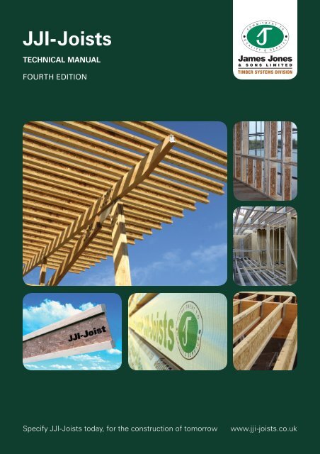
<strong>JJI</strong>-<strong>Joists</strong><br />
TECHNICAL MANUAL<br />
FOURTH EDITION<br />
Specify <strong>JJI</strong>-<strong>Joists</strong> today, for the construction of tomorrow<br />
www.jji-joists.co.uk
CONTENTS<br />
01 INTRODUCTION<br />
02 THE SYSTEM<br />
03 GENERAL INFORMATION<br />
04 ENVIRONMENTAL INFORMATION<br />
05 <strong>JJI</strong>-JOISTS<br />
08 SERVICE HOLES IN <strong>JJI</strong>-JOISTS<br />
09 FIRE AND DURABILITY<br />
10 ACOUSTIC PERFORMANCE<br />
11 BJ-BEAM (GLULAM)<br />
14 BJ-BEAM FIXING DETAILS<br />
17 METALWORK<br />
18 FLOOR DESIGN<br />
19 DOMESTIC INTERMEDIATE AND APARTMENT FLOOR SPAN TABLES<br />
20 HEALTH AND SAFETY – TEMPORARY BRACING<br />
21 SITE STORAGE AND RESTRICTIONS<br />
22 INDICATIVE FLOOR DETAILING – F DETAILS<br />
31 ROOF DESIGN<br />
32 <strong>JJI</strong>-JOIST FLAT ROOFS<br />
33 <strong>JJI</strong>-JOIST PITCHED RAFTERS<br />
35 INDICATIVE ROOF DETAILING – R DETAILS<br />
38 WALL DESIGN<br />
39 <strong>JJI</strong>-JOIST THERMAL PERFORMANCE<br />
40 INDICATIVE WALL DETAILING – W DETAILS<br />
41 GLOSSARY<br />
We currently offer a face to face seminar on Engineered Wood<br />
Products for Modern Methods of Construction. These are<br />
offered for larger Construction Practises throughout the UK<br />
and Ireland.<br />
Please visit our website to request a face to face seminar and<br />
find out how to take our online CPD Seminar.<br />
Whilst every effort was made to ensure the accuracy of this publication at the time of printing<br />
James Jones & Sons cannot be held responsible for changes to <strong>Build</strong>ing Regulations, NHBC<br />
Standards etc.<br />
For the most up-to-date information please visit our web site: www.jji-joists.co.uk
INTRODUCTION<br />
1<br />
INTRODUCTION TO JAMES JONES & SONS<br />
James Jones & Sons is the UK’s leading manufacturer of I-<strong>Joists</strong><br />
based at its Timber Systems Division in Forres, Morayshire.<br />
The Timber Systems Division prides itself on building strong<br />
partnerships throughout the supply chain, concentrating on its<br />
core values of quality and service.<br />
<strong>JJI</strong>-<strong>Joists</strong> are manufactured under the strictest quality and<br />
environmental standards, and this new edition of the Technical<br />
Manual outlines the applications and versatility of <strong>JJI</strong>-<strong>Joists</strong>.<br />
The range is manufactured to UK sizes and specifications,<br />
and is available on a Just-In-Time basis from a comprehensive<br />
stock holding. The entire production and distribution process<br />
has been audited by third party accreditation systems, and<br />
a Life Cycle Assessment has been carried out to ensure full<br />
sustainability and environmental compliance.<br />
Through the use of our bespoke, dedicated software<br />
programmes, <strong>JJI</strong>-<strong>Joists</strong> can be specified and engineered to<br />
exacting standards, for applications including floors and roofs<br />
of both domestic and commercial buildings.<br />
<strong>JJI</strong>-<strong>Joists</strong> are part of a comprehensive building system and are<br />
complimented by glulam and metal connectors and this manual<br />
highlights their use and combinations.<br />
<strong>JJI</strong>-<strong>Joists</strong> are sold through dedicated Distributors, merchants,<br />
timber frame kit manufacturers and roof truss manufacturers<br />
situated strategically across the UK and Ireland. These<br />
combined resources, backed up by dedicated James Jones<br />
& Sons personnel, ensure that the design, specification and<br />
supply of <strong>JJI</strong>-<strong>Joists</strong> is seamless and of the highest quality.<br />
ROOTS<br />
Mr James Jones started trading in timber and allied products in<br />
the middle of the nineteenth century. Since being incorporated<br />
in 1905, James Jones & Sons has grown both organically and<br />
by acquisition.<br />
THE COMPANY<br />
James Jones & Sons is one of the largest suppliers of British<br />
Timber in the UK today. The company’s sawmills are strategically<br />
placed to take advantage of the increasing supply of saw logs<br />
being produced from post war plantations. These are bought<br />
from both private and state owned forests as well as woodlands<br />
owned and managed by the company.<br />
FAMILY CONCERN<br />
James Jones & Sons is a real family business. Even with a staff of<br />
over 500 it has the culture of a family firm. Like any good family,<br />
the company cares for its members. That concern extends to<br />
whole communities in rural areas where the company is a<br />
major employer. There is also an equal concern for customer<br />
satisfaction. The company’s mission is to maintain the highest<br />
standards of quality and service in the industry.<br />
CUTTING EDGE<br />
The company strives to maintain its competitive advantages.<br />
Variety of product is one. Wood is harvested and processed<br />
for specific markets and end uses such as: Construction,<br />
Palletwood, Packaging and Fencing.<br />
James Jones & Sons has a team of highly trained professionals<br />
who look after the purchasing and harvesting of round timber,<br />
making sure that the right logs go to the right mill where they<br />
can be processed to best advantage. Good relationships with<br />
forest owners are vital and in most cases are of many years<br />
standing thus providing the right background for the purchase<br />
of our raw material.<br />
Quality comes from modern sawmills staffed by experienced<br />
people. James Jones & Sons is fortunate in having many<br />
people who are experts in their field and who know about and<br />
understand wood. This ensures the quality of our products is<br />
maintained at the highest level.<br />
THE FUTURE<br />
<br />
<br />
<br />
<br />
<br />
<br />
<br />
<br />
<br />
United Box<br />
<br />
<br />
As well as investing in state of the art technology for our<br />
traditional sawmilling business, James Jones & Sons has<br />
taken the strategic decision to invest in and develop more<br />
innovative products. The <strong>JJI</strong>-Joist, manufactured by James<br />
Jones & Sons, Timber Systems Division, is the direct result<br />
of one of the new technologies that has been embraced by<br />
the company. Following the successful launch of the <strong>JJI</strong>-Joist<br />
range in 1999 the Timber Systems Division have added a fully<br />
automated second production line along with a highly efficient<br />
finger jointing line to keep up with demand. In addition to the<br />
production investment, the Division has also set up a technical<br />
and design office to provide a full design and engineering<br />
support service.
2 THE SYSTEM<br />
THE <strong>JJI</strong>-JOIST SYSTEM<br />
The <strong>JJI</strong>-Joist system relies on a unique combination of<br />
engineered products designed to compliment each other and<br />
deliver outstanding performance.<br />
<strong>JJI</strong>-JOISTS<br />
The work horse of the system, a versatile light weight structural<br />
member ideal for floor joists, rafters, purlins and wall studs.<br />
SOFTWARE<br />
The <strong>JJI</strong>-Joist system is fully supported by three Windows<br />
based software packages written in the UK to provide fast<br />
and cost effective design solutions for today’s construction<br />
industry.<br />
These packages are regularly updated to ensure compliance<br />
with ever changing <strong>Build</strong>ing Regulations and Codes of Practice,<br />
each new version incorporating new features and developments<br />
to help the designer maximise the benefits of the system.<br />
JoistMaster is an extremely powerful beam design tool, which<br />
enables the specifier to quickly assess the most cost effective<br />
joist solution, tailored to his/her particular design requirements,<br />
and provide a calculation printout suitable for Local Authority<br />
approval. JoistMaster is freely available to download from<br />
www.jji-joists.co.uk<br />
For more information see page 5<br />
BJ-BEAM (GLULAM)<br />
For the most demanding applications, high strength and<br />
stiffness combined with dimensional stability make this the<br />
ideal choice for heavily loaded members in floors, roofs and<br />
walls.<br />
FloorMaster is a comprehensive floor design and layout<br />
package allowing trained designers to quickly and accurately<br />
produce detailed layout drawings, installation details, material<br />
call-offs, calculations and design quotations for any building<br />
footprint.<br />
METALWORK<br />
For more information see page 11<br />
The key to making the system work is being able to connect<br />
everything together. A comprehensive range of connectors<br />
designed specifically for the <strong>JJI</strong>-Joist system are available from<br />
two approved suppliers.<br />
OptiMaster is a stock optimisation package designed to work<br />
with the output from FloorMaster.<br />
For more information see page 17
GENERAL INFORMATION<br />
3<br />
DISTRIBUTION<br />
The <strong>JJI</strong>-Joist system is available from a network of builders/<br />
timber merchants and timber frame and engineered timber<br />
system manufacturers providing local, quality expertise.<br />
APPROVALS<br />
<strong>JJI</strong>-<strong>Joists</strong> are an accepted building material within the<br />
construction industry thanks to third party certification from both<br />
the British Board of Agrément and BM TRADA Certification.<br />
CERTIFICATE NUMBER EWP-0001<br />
BM TRADA<br />
ENGINEERED WOOD PRODCUTS<br />
BBA certification and BMTRADA Q-Mark are recognised by<br />
NHBC, Zurich, Local Authority <strong>Build</strong>ing Control and others.<br />
These Distributors are trained to use our software and<br />
understand the correct use and specification of our products.<br />
This training is ongoing and ensures our Distributors have<br />
the skills required to provide an efficient, cost-effective,<br />
<strong>JJI</strong>-Joist solution.<br />
Distributor details are available to download from<br />
www.jji-joists.co.uk<br />
<strong>JJI</strong>-JOISTS UK STOCKISTS & TECHNICAL SUPPORT<br />
James Jones & Sons are founder members of the UK Timber<br />
Frame Association (UKTFA) Engineered Wood Products<br />
Committee and were involved in the drafting of the Code of<br />
Practice for the Design of Engineered Wood Products which<br />
provides guidance on the design of structures using I-joists.<br />
Greshop Industrial Estate,<br />
Forres, Moray, IV36 1JJ<br />
General Support<br />
01309 671111<br />
Regional Support<br />
James Smith<br />
07500 016773<br />
Lynford Chambers<br />
07879 888216<br />
Peter Barker<br />
07977 283781<br />
Mark Tilston<br />
07977 283756<br />
www.jji-joists.co.uk<br />
QUALITY CONTROL AND QUALITY ASSURANCE<br />
The success of a manufactured product is often determined by<br />
its quality. <strong>It</strong> is for this reason the James Jones & Sons, Timber<br />
Systems Division maintains a thorough Quality Assurance<br />
program which enables us to achieve our goal of producing a<br />
consistent and uniform product of exceptionally high standards.<br />
<strong>JJI</strong>-<strong>Joists</strong> are manufactured under a Quality Assurance scheme<br />
which complies with ISO 9001:2008 and CE marking.<br />
<strong>JJI</strong>–Joist Distributor<br />
Timber Frame Kit Supplier<br />
CUSTOMER SERVICES AND TECHNICAL SUPPORT<br />
James Jones & Sons, Timber Systems Division has a highly<br />
trained team of Technical, Engineering and Sales personnel<br />
providing UK and Irish national coverage to ensure simple, safe<br />
and quick installation of <strong>JJI</strong>-Joist systems. A summary of the<br />
services offered is given below.<br />
<br />
<br />
<br />
<br />
<br />
<br />
RESEARCH AND DEVELOPMENT<br />
The Timber Systems Division has an ongoing research and<br />
development program designed to find new applications<br />
for existing products and to improve the performance in<br />
current applications. In addition to this, production methods<br />
and technology are continuously reviewed and improved to<br />
maximise quality and efficiency.
4 ENVIRONMENTAL INFORMATION<br />
ENVIRONMENTAL MANAGEMENT<br />
Environmental considerations are a very important factor in<br />
the production of <strong>JJI</strong>-<strong>Joists</strong>. Our certified ISO 14001:2004<br />
Environmental Management System has enabled the company<br />
to target key areas to reduce the impacts of our activities on<br />
the environment.<br />
The introduction of sustainable heating systems and the<br />
continuous commitment to waste minimisation, energy<br />
savings and recycling of materials used ensures the delivery of<br />
<strong>JJI</strong>-<strong>Joists</strong> with the smallest environmental footprint possible.<br />
The constant consideration of the environment in our current<br />
and future plans has shaped our purchasing policy to choose<br />
only those technologies that can prevent pollution and improve<br />
our environmental performance.<br />
The high competence of our employees enables our<br />
environmental objectives to be implemented and exceeded<br />
every year. The support given by management ensures that a<br />
continual improvement culture in environmental performance<br />
is always present at the very centre of all our activities. As<br />
environmental considerations affect the whole <strong>JJI</strong>-Joist supply<br />
chain, we are engaged in continuous dialogue with our suppliers<br />
and distributors to minimise this impact. One result from these<br />
efforts has been the mutual decision to supply only timber from<br />
sustainable sources.<br />
Therefore, our commitment to ISO 14001:2004 not only<br />
guarantees you compliance with all current and forthcoming<br />
legislation but delivers a <strong>JJI</strong>-Joist with excellent environmental<br />
credentials and minimal impacts throughout its life cycle.<br />
LIFE CYCLE<br />
True sustainability can only be measured and improved upon<br />
by assessing all environmental impacts associated with the<br />
sourcing, transport and manufacture of that product (ie. from<br />
the forest to the end user).<br />
<strong>JJI</strong>-<strong>Joists</strong> can help to mitigate climate change as timber acts<br />
as a carbon sink. Carbon dioxide (CO ² ) is absorbed by trees<br />
and used to create wood. This CO ² is only released back into<br />
the environment when the joists come to the end of their<br />
lifetime. As only sustainable timber is used for the production<br />
of <strong>JJI</strong>-<strong>Joists</strong>, other trees are planted to replace harvested ones<br />
immediately, closing the CO ² cycle and contributing to keep<br />
a constant or even increasing volume of CO ² locked away<br />
from the atmosphere where it cannot contribute to climate<br />
change.<br />
The continuous planning and research to minimise transport,<br />
purchase new formulation resins and use biomass as a way to<br />
substitute fossil fuels ensures that impacts throughout the life<br />
cycle of <strong>JJI</strong>-<strong>Joists</strong> are minimal.<br />
These low impacts have been recognised by the current scheme<br />
created to quantify environmental impacts of products such as<br />
BRE environmental profiles. Scores for this scheme are used in<br />
the assessment process of 'The Code for Sustainable Homes' in<br />
England and Wales and 'Ecohomes' in Scotland. Timber I-joists<br />
such as <strong>JJI</strong>-<strong>Joists</strong> achieve the best scores in this scheme (A+)<br />
and therefore can help specifiers to achieve the Zero Carbon<br />
House level.<br />
Flanges<br />
Electricity<br />
supply<br />
Natural<br />
gas supply<br />
Diesel<br />
supply<br />
Water<br />
supply<br />
CHAIN OF CUSTODY<br />
The UK Government policy on timber purchasing has stated that<br />
timber should only be purchased from legal and sustainable<br />
sources. Increasingly, both public and private sectors are<br />
encouraged to follow this policy.<br />
Sustainable timber supply has always been integral to the<br />
manufacture of our engineered wood products. <strong>JJI</strong>-<strong>Joists</strong> meets<br />
this requirement as they can be specified as FSC Certified or PEFC<br />
Certified. These claims are independently verified through BM<br />
TRADA Forest Product certification scheme.<br />
The Central Point of Expertise on Timber Procurement (CPET),<br />
the UK Government advisory committee for timber purchasing,<br />
has established the different options available for companies<br />
to prove that timber is legal and sustainable. In this way,<br />
compliance with an existing certification scheme approved<br />
by CPET is considered to be sufficient. Both FSC and PEFC<br />
schemes have been approved as a way to deliver legal and<br />
sustainable timber.<br />
OSB<br />
Glue<br />
Packaging<br />
Emissions<br />
to air<br />
THERMAL PERFORMANCE<br />
Emissions<br />
to water<br />
Co-products<br />
Emissions<br />
to land<br />
Other advantages of using <strong>JJI</strong>-<strong>Joists</strong> are their superior strength<br />
to weight ratio and readily available deep sections (up to 450mm)<br />
when compared with solid timber. In this way more insulation can<br />
be used within the building envelope and significant savings in<br />
heating can be achieved.<br />
The thin web used in <strong>JJI</strong>-<strong>Joists</strong> contributes to minimise repeated<br />
thermal bridging in timber frame structures enabling <strong>JJI</strong>-<strong>Joists</strong><br />
to achieve better U-values than solid timber. This property<br />
makes <strong>JJI</strong>-<strong>Joists</strong> ideal as a structural member in roofs and walls<br />
in low energy buildings.<br />
TT-COC 1503 & 1064<br />
BMT-PEFC-0105<br />
The UK government has already expressed their preference<br />
for better insulated and airtight building envelopes as a way<br />
to reduce energy consumption. The adoption of insulated<br />
structures using <strong>JJI</strong>-<strong>Joists</strong> and designed according to principles<br />
such as Passivhaus can significantly reduce the energy<br />
requirements for heating and this approach will be essential<br />
to achieve a truly Zero Carbon House.
<strong>JJI</strong>-JOISTS<br />
5<br />
INTRODUCTION<br />
A <strong>JJI</strong>-Joist is a composite engineered timber joist, combining<br />
45mm deep high-grade finger jointed softwood flanges (C24)<br />
with a 9mm thick oriented strand board (OSB/3) web. Four<br />
flange widths are available at 47, 63, 72 and 97mm wide.<br />
<strong>JJI</strong>-JOIST RANGE AND TOLERANCES<br />
<strong>JJI</strong>-<strong>Joists</strong> are available in a comprehensive range of sizes,<br />
designed specifically for the UK market. <strong>JJI</strong>-<strong>Joists</strong> are available<br />
in lengths of up to 12m.<br />
COMPOSITION<br />
<strong>JJI</strong>-JOIST FLANGE SIZES<br />
A+ B+ C D<br />
Softwood flanges<br />
High tensile and compressive<br />
strength is used to carry the<br />
bending loads which are<br />
greatest at the top and<br />
bottom of the section<br />
9mm OSB/3 Web<br />
High shear strength is used<br />
to carry the shear loads which<br />
are greatest at the mid depth<br />
of the section<br />
47mm 63mm 72mm 97mm<br />
45mm<br />
45mm<br />
These materials have different specific properties and by<br />
combining the two materials in this way to form a composite<br />
section you can use the strengths of each one where it is<br />
needed most. This results in the new section outperforming<br />
the individual materials that it is made from (the sum is greater<br />
than its parts) making it more structurally efficient.<br />
Using advanced technology these components are combined to<br />
produce an innovative alternative to conventional construction<br />
timber with many additional advantages.<br />
ADVANTAGES<br />
<strong>JJI</strong>-<strong>Joists</strong> are designed to give a superior strength to weight<br />
ratio enabling the manufacture of longer and lighter structural<br />
members. The <strong>JJI</strong>-Joist, with a softwood flange:<br />
<br />
<br />
<br />
<br />
<br />
<br />
<br />
<br />
<br />
<br />
<br />
<br />
Joist Depth<br />
(mm)<br />
A+<br />
47mm<br />
<strong>JJI</strong>-Joist Flange Sizes<br />
B+<br />
63mm<br />
C<br />
72mm<br />
D<br />
97mm<br />
Timber<br />
Grade<br />
145 ✓ C24<br />
195 ✓ ✓ ✓ ✓ C24<br />
220 ✓ ✓ ✓ ✓ C24<br />
235 ✓ ✓ ✓ ✓ C24<br />
245 ✓ ✓ ✓ ✓ C24<br />
300 ✓ ✓ ✓ ✓ C24<br />
350 ✓ ✓ C24<br />
400 ✓ ✓ C24<br />
450 ✓ C24<br />
Table 1. <strong>JJI</strong>-Joist Product Range<br />
Member Dimension<br />
Tolerance (mm)<br />
Overall Joist Length +/-3.0<br />
Overall Joist Depth +/-2.0<br />
Flange Thickness/Depth +/-2.0<br />
Web Thickness +/-0.8<br />
Table 2. <strong>JJI</strong>-Joist Manufacturing Tolerance<br />
<strong>JJI</strong>-JOIST IDENTIFICATION AND MARKING<br />
<strong>JJI</strong>-<strong>Joists</strong> are identified by an alpha numeric code that specifies<br />
the joist depth, flange size and flange grade (see example<br />
below). This code is printed at regular intervals along the<br />
centreline of the web along with the production time and date<br />
to facilitate on-site identification and traceability.<br />
ID<br />
<strong>JJI</strong>195 B+24<br />
James<br />
Jones<br />
I-Joist<br />
195mm<br />
Deep<br />
C24<br />
Timber<br />
Flange<br />
‘B+’ Flange<br />
63mm Wide<br />
DD.MM.YY<br />
Production<br />
Batch Code<br />
In addition to the above information, the clear warning 'DO NOT<br />
CUT FLANGES' is printed along the length of each flange as a<br />
precaution against creating unnecessary structural damage.
6 <strong>JJI</strong>-JOISTS<br />
<strong>JJI</strong>-JOIST PROPERTIES<br />
<strong>It</strong> is possible to design <strong>JJI</strong>-Joist structures using either a<br />
Permissible Stress Design Code (BS 5268-2) or a Limit State<br />
Design Code (EN1995-1-1/Eurocode 5). Each code requires<br />
properties that are derived and presented in a different way.<br />
Permissible stress design properties, intended for use with<br />
BS 5268-2 and Characteristic capacities, intended for use with<br />
Eurocode 5, can be found in TRADA Q-Mark EWP-0001.<br />
Joist Type<br />
Depth<br />
Bending<br />
moment<br />
capacity<br />
Bending<br />
stiffness<br />
Shear<br />
strength<br />
capacity<br />
Shear<br />
stiffness<br />
Intermediate bearing<br />
capacity – minimum<br />
89mm bearing length<br />
End bearing capacity<br />
– minimum 45mm<br />
bearing length<br />
End bearing capacity<br />
– minimum 89mm<br />
bearing length<br />
M EI V GA N/S W/S N/S W/S N/S W/S W<br />
Weight<br />
per metre<br />
length<br />
(mm) (kNm) (10 9 Nmm 2 ) (kN) (10 6 N) (kN) (kN) (kN) (kN) (kN) (kN) (kg/m)<br />
<strong>JJI</strong> 145 A+ 145 1.64 139.6 3.12 0.550 5.36 6.92 2.78 3.60 3.38 4.55 2.26<br />
<strong>JJI</strong> 195 A+ 195 2.40 305.1 3.48 0.907 5.66 7.95 2.78 5.27 3.38 5.27 2.56<br />
<strong>JJI</strong> 195 B+ 3.05 424.7 3.87 0.907 7.18 9.28 3.73 5.27 4.31 6.10 3.21<br />
<strong>JJI</strong> 195 C 3.40 505.6 4.07 0.907 8.21 10.61 4.22 5.51 4.31 6.97 3.57<br />
<strong>JJI</strong> 195 D 4.32 740.5 4.60 0.907 8.73 12.69 4.22 7.42 4.31 9.39 4.58<br />
<strong>JJI</strong> 220 A+ 220 2.79 407.4 3.71 1.086 6.25 7.95 2.96 5.27 3.45 5.27 2.70<br />
<strong>JJI</strong> 220 B+ 3.54 588.5 4.09 1.086 7.18 9.28 3.73 5.27 4.31 6.10 3.35<br />
<strong>JJI</strong> 220 C 3.95 667.3 4.29 1.086 8.21 10.61 4.22 5.51 4.31 6.97 3.72<br />
<strong>JJI</strong> 220 D 5.02 941.3 4.81 1.086 8.73 12.69 4.22 7.42 4.31 9.39 4.73<br />
<strong>JJI</strong> 235 A+ 235 3.03 472.4 3.85 1.193 6.60 7.95 3.13 5.27 3.62 5.27 2.79<br />
<strong>JJI</strong> 235 B+ 3.84 678.1 4.22 1.193 7.18 9.28 3.73 5.27 4.31 6.10 3.44<br />
<strong>JJI</strong> 235 C 4.28 771.3 4.42 1.193 8.21 10.61 4.22 5.51 4.31 6.97 3.80<br />
<strong>JJI</strong> 235 D 5.44 1088.0 4.95 1.193 8.73 12.69 4.22 7.42 4.31 9.39 4.82<br />
<strong>JJI</strong> 245 A+ 245 3.19 518.0 3.95 1.265 6.84 7.95 3.24 5.27 3.72 5.27 2.85<br />
<strong>JJI</strong> 245 B+ 4.04 737.2 4.32 1.265 7.18 9.28 3.73 5.27 4.31 6.10 3.50<br />
<strong>JJI</strong> 245 C 4.50 844.4 4.52 1.265 8.21 10.61 4.22 5.51 4.31 6.97 3.86<br />
<strong>JJI</strong> 245 D 5.72 1195.4 5.04 1.265 8.73 12.69 4.22 7.42 4.31 9.39 4.87<br />
<strong>JJI</strong> 300 A+ 300 4.09 816.3 4.54 1.658 6.17 7.95 3.13 5.27 3.86 5.27 3.17<br />
<strong>JJI</strong> 300 B+ 5.17 1121.9 4.88 1.658 7.18 9.28 3.73 5.27 4.14 6.10 3.82<br />
<strong>JJI</strong> 300 C 5.75 1319.5 5.07 1.658 8.21 10.61 3.95 5.51 4.14 6.97 4.18<br />
<strong>JJI</strong> 300 D 7.29 1899.0 5.59 1.658 8.73 12.69 3.95 7.42 4.14 9.39 5.20<br />
<strong>JJI</strong> 350 C 350 6.90 1899.6 5.62 2.015 8.21 10.61 3.35 5.51 3.57 6.97 4.48<br />
<strong>JJI</strong> 350 D 8.74 2647.6 6.12 2.015 8.73 12.69 3.35 7.42 3.57 9.39 5.49<br />
<strong>JJI</strong> 400 C 400 8.08 2673.0 6.19 2.373 8.21 10.61 2.69 5.51 3.32 6.97 4.77<br />
<strong>JJI</strong> 400 D 10.20 3428.0 6.68 2.373 8.44 12.69 2.69 7.42 3.32 9.39 5.78<br />
<strong>JJI</strong> 450 D 450 11.69 4170.4 7.26 2.730 7.04 12.69 2.37 7.42 3.02 9.39 6.07<br />
Table 3. Long Term Permissible Design Properties for <strong>JJI</strong>-<strong>Joists</strong> (BS 5268-2)<br />
Joist Type<br />
Depth<br />
Bending<br />
moment<br />
capacity<br />
Bending<br />
stiffness<br />
Shear<br />
strength<br />
capacity<br />
Shear<br />
stiffness<br />
Intermediate bearing<br />
capacity – minimum<br />
89mm bearing length<br />
End bearing capacity<br />
– minimum 45mm<br />
bearing length<br />
End bearing capacity<br />
– minimum 89mm<br />
bearing length<br />
M EI V GA N/S W/S N/S W/S N/S W/S W<br />
Weight<br />
per metre<br />
length<br />
(mm) (kNm) (10 9 Nmm 2 ) (kN) (10 6 N) (kN) (kN) (kN) (kN) (kN) (kN) (kg/m)<br />
<strong>JJI</strong> 145 A 145 1.59 139.6 3.07 0.550 5.13 6.63 2.65 3.44 3.25 4.36 2.18<br />
<strong>JJI</strong> 195 A 195 2.32 290.8 3.43 0.907 5.66 7.95 2.68 5.27 3.25 5.27 2.48<br />
<strong>JJI</strong> 195 B 2.93 397.7 3.80 0.907 6.84 8.84 3.57 5.27 4.26 5.81 3.08<br />
<strong>JJI</strong> 220 A 220 2.70 383.5 3.66 1.086 6.25 7.95 2.96 5.27 3.45 5.27 2.62<br />
<strong>JJI</strong> 220 B 3.40 562.3 4.02 1.086 6.84 8.84 3.57 5.27 4.26 5.81 3.23<br />
<strong>JJI</strong> 235 A 235 2.93 445.6 3.81 1.193 6.60 7.95 3.13 5.27 3.62 5.27 2.71<br />
<strong>JJI</strong> 235 B 3.69 647.1 4.16 1.193 6.84 8.84 3.57 5.27 4.26 5.81 3.32<br />
<strong>JJI</strong> 245 A 245 3.08 489.8 3.91 1.265 6.84 7.95 3.24 5.27 3.72 5.27 2.77<br />
<strong>JJI</strong> 245 B 3.89 701.5 4.25 1.265 6.84 8.84 3.57 5.27 4.26 5.81 3.38<br />
<strong>JJI</strong> 300 A 300 3.95 779.4 4.49 1.658 6.17 7.95 3.13 5.27 3.86 5.27 3.09<br />
<strong>JJI</strong> 300 B 4.97 1056.0 4.82 1.658 6.84 8.84 3.57 5.27 4.15 5.81 3.70<br />
Table 3a. Long Term Permissible Design Properties for <strong>JJI</strong>-<strong>Joists</strong> (BS5268-2) – A & B Range<br />
Notes for Table 3 and 3a<br />
1. Do not mix values from Tables 3 and 3(a) and Tables 4 and 4(a)<br />
2. Values given are for long term load durations only (k 3 =1.0)<br />
3. Values are applicable to joists in Service Class 1 only<br />
4. N/S: no web stiffeners required, W/S: web stiffeners required<br />
5. All strength properties are given for <strong>JJI</strong>-<strong>Joists</strong> used in load sharing situations. Non-load sharing values can be obtained as follows:<br />
Moment, Shear and Bearing Capacity – Divide the tabulated value by 1.1 (k 8 = 1.1)<br />
6. Minimum end bearing length = 45mm, minimum intermediate bearing length = 89mm<br />
7. End bearing capacities for bearing lengths between 45-89mm can be found by linear interpolation<br />
8. The long term uniformly distributed bottom flange pull-off load is 5.5kN/m<br />
9. For Residential Floors within Self Contained Dwellings with a maximum imposed load of 1.5kN/m 2 , the <strong>JJI</strong>-Joist Moment, Shear and Bearing capacities can<br />
be multiplied by 1.12 (k dom = 1.12)<br />
CERTIFICATE NUMBER EWP-0001<br />
BM TRADA<br />
ENGINEERED WOOD PRODCUTS
<strong>JJI</strong>-JOISTS<br />
7<br />
Joist Type<br />
Depth<br />
Bending<br />
moment<br />
capacity<br />
Bending<br />
stiffness<br />
Shear<br />
strength<br />
capacity<br />
Shear<br />
stiffness<br />
Intermediate bearing<br />
capacity – minimum<br />
89mm bearing length<br />
End bearing capacity<br />
– minimum 45mm<br />
bearing length<br />
End bearing capacity<br />
– minimum 89mm<br />
bearing length<br />
M EI V GA N/S W/S N/S W/S N/S W/S W<br />
Weight<br />
per metre<br />
length<br />
(mm) (kNm) (10 9 Nmm 2 ) (kN) (10 6 N) (kN) (kN) (kN) (kN) (kN) (kN) (kg/m)<br />
<strong>JJI</strong> 145 A+ 145 3.89 139.6 9.54 0.748 16.37 16.37 8.50 8.50 10.33 10.76 2.26<br />
<strong>JJI</strong> 195 A+ 195 5.67 305.1 10.64 1.234 16.37 16.37 8.50 8.50 10.31 10.76 2.56<br />
<strong>JJI</strong> 195 B+ 7.20 424.7 11.82 1.234 21.94 21.94 11.39 11.39 13.16 14.42 3.21<br />
<strong>JJI</strong> 195 C 8.03 505.6 12.44 1.234 25.07 25.07 12.90 13.02 13.16 16.48 3.57<br />
<strong>JJI</strong> 195 D 10.22 740.5 14.06 1.234 26.66 30.00 12.90 17.54 13.16 22.20 4.58<br />
<strong>JJI</strong> 220 A+ 220 6.60 407.4 11.33 1.477 16.37 16.37 8.50 8.50 10.31 10.76 2.70<br />
<strong>JJI</strong> 220 B+ 8.37 588.5 12.48 1.477 21.94 21.94 11.39 11.39 13.16 14.42 3.35<br />
<strong>JJI</strong> 220 C 9.32 667.3 13.09 1.477 25.07 25.07 12.90 13.02 13.16 16.48 3.72<br />
<strong>JJI</strong> 220 D 11.86 941.3 14.71 1.477 26.66 30.00 12.90 17.54 13.16 22.20 4.73<br />
<strong>JJI</strong> 235 A+ 235 7.17 472.4 11.77 1.623 16.37 16.37 8.50 8.50 10.31 10.76 2.79<br />
<strong>JJI</strong> 235 B+ 9.08 678.1 12.90 1.623 21.94 21.94 11.39 11.39 13.16 14.42 3.44<br />
<strong>JJI</strong> 235 C 10.11 771.3 13.51 1.623 25.07 25.07 12.90 13.02 13.16 16.48 3.80<br />
<strong>JJI</strong> 235 D 12.85 1088.0 15.12 1.623 26.66 30.00 12.90 17.54 13.16 22.20 4.82<br />
<strong>JJI</strong> 245 A+ 245 7.54 518.0 12.08 1.720 16.37 16.37 8.50 8.50 10.31 10.76 2.85<br />
<strong>JJI</strong> 245 B+ 9.55 737.2 13.19 1.720 21.94 21.94 11.39 11.39 13.16 14.42 3.50<br />
<strong>JJI</strong> 245 C 10.64 844.4 13.80 1.720 25.07 25.07 12.90 13.02 13.16 16.48 3.86<br />
<strong>JJI</strong> 245 D 13.52 1195.4 15.40 1.720 26.66 30.00 12.90 17.54 13.16 22.20 4.87<br />
<strong>JJI</strong> 300 A+ 300 9.67 816.3 13.86 2.255 16.37 16.37 8.50 8.50 10.31 10.76 3.17<br />
<strong>JJI</strong> 300 B+ 12.21 1121.9 14.91 2.255 21.94 21.94 11.39 11.39 12.64 14.42 3.82<br />
<strong>JJI</strong> 300 C 13.58 1319.5 15.49 2.255 25.07 25.07 12.08 13.02 12.64 16.48 4.18<br />
<strong>JJI</strong> 300 D 17.22 1899.0 17.07 2.255 26.66 30.00 12.08 17.54 12.64 22.20 5.20<br />
<strong>JJI</strong> 350 C 350 16.31 1899.6 17.16 2.741 25.07 25.07 10.22 13.02 10.91 16.48 4.48<br />
<strong>JJI</strong> 350 D 20.65 2647.6 18.70 2.741 26.66 30.00 10.22 17.54 10.91 22.20 5.49<br />
<strong>JJI</strong> 400 C 400 19.09 2673.0 18.91 3.227 25.07 25.07 8.20 13.02 10.15 16.48 4.77<br />
<strong>JJI</strong> 400 D 24.12 3428.0 20.41 3.227 25.79 30.00 8.20 17.54 10.15 22.20 5.78<br />
<strong>JJI</strong> 450 D 450 27.64 4170.4 22.18 3.713 21.50 30.00 6.79 17.54 9.21 22.20 6.07<br />
Table 4. Characteristic Capacities for <strong>JJI</strong>-<strong>Joists</strong> (Eurocode 5)<br />
Joist Type<br />
Depth<br />
Bending<br />
moment<br />
capacity<br />
Bending<br />
stiffness<br />
Shear<br />
strength<br />
capacity<br />
Shear<br />
stiffness<br />
Intermediate bearing<br />
capacity – minimum<br />
89mm bearing length<br />
End bearing capacity<br />
– minimum 45mm<br />
bearing length<br />
End bearing capacity<br />
– minimum 89mm<br />
bearing length<br />
M EI V GA N/S W/S N/S W/S N/S W/S W<br />
Weight<br />
per metre<br />
length<br />
(mm) (kNm) (10 9 Nmm 2 ) (kN) (10 6 N) (kN) (kN) (kN) (kN) (kN) (kN) (kg/m)<br />
<strong>JJI</strong> 145 A 145 3.75 139.6 9.38 0.748 15.67 15.67 8.1 8.14 9.92 10.30 2.18<br />
<strong>JJI</strong> 195 A 195 5.48 290.8 10.49 1.234 15.67 15.67 8.1 8.14 9.92 10.30 2.48<br />
<strong>JJI</strong> 195 B 6.92 397.7 11.61 1.234 20.89 20.89 10.9 10.85 13.02 13.73 3.08<br />
<strong>JJI</strong> 220 A 220 6.37 383.5 11.18 1.477 15.67 15.67 8.1 8.14 9.92 10.30 2.62<br />
<strong>JJI</strong> 220 B 8.05 562.3 12.27 1.477 20.89 20.89 10.9 10.85 13.02 13.73 3.23<br />
<strong>JJI</strong> 235 A 235 6.92 445.6 11.62 1.623 15.67 15.67 8.1 8.14 9.92 10.30 2.71<br />
<strong>JJI</strong> 235 B 8.73 647.1 12.70 1.623 20.89 20.89 10.9 10.85 13.02 13.73 3.32<br />
<strong>JJI</strong> 245 A 245 7.28 489.8 11.93 1.720 15.67 15.67 8.1 8.14 9.92 10.30 2.77<br />
<strong>JJI</strong> 245 B 9.19 701.5 12.99 1.720 20.89 20.89 10.9 10.85 13.02 13.73 3.38<br />
<strong>JJI</strong> 300 A 300 9.34 779.4 13.73 2.255 15.67 15.67 8.1 8.14 9.92 10.30 3.09<br />
<strong>JJI</strong> 300 B 11.75 1056.0 14.72 2.255 20.89 20.89 10.9 10.85 12.66 13.73 3.70<br />
Table 4a. Characteristic Capacities for <strong>JJI</strong>-<strong>Joists</strong> (Eurocode 5) – A & B Range<br />
CERTIFICATE NUMBER EWP-0001<br />
Notes for Table 4 and 4a:<br />
1. Do not mix values from Tables 3 and 3(a) and Tables 4 and 4(a)<br />
2. N/S: no web stiffeners required, W/S: web stiffeners required<br />
3. All strength properties are given for <strong>JJI</strong>-<strong>Joists</strong> used in load sharing<br />
situations. Non-load sharing values can be obtained as follows:<br />
Moment, Shear and Bearing Capacity – Divide the tabulated value by 1.1<br />
(k sys = 1.1)<br />
4. Minimum end bearing length = 45mm, minimum intermediate bearing<br />
length = 89mm<br />
5. Advice on choosing appropriate partial factors for limit state design can be<br />
found in TRADA Q-Mark EWP-0001<br />
<strong>JJI</strong> POINT LOADS AND UDL<br />
PERMISSIBLE <strong>JJI</strong>-JOIST<br />
VERTICAL LOAD CAPACITIES<br />
<strong>JJI</strong> Joist Depth<br />
Maximum long term load per<br />
metre run (kN/m)<br />
BM TRADA<br />
ENGINEERED WOOD PRODCUTS<br />
Maximum single point<br />
load (kN)<br />
195 25.0 12.0<br />
220 20.0 12.0<br />
235 20.0 12.0<br />
245 19.0 12.0<br />
300 17.0 10.0<br />
350 15.0 10.0<br />
400 13.0 8.0<br />
450 12.0 8.0<br />
Table 5. Permissible <strong>JJI</strong>-Joist Vertical Loads<br />
Notes for Table 5:<br />
1. Loads are given for long term load duration. Modification factor k 3<br />
has the following values for other load durations 1.25 Medium Term,<br />
1.5 Short Term
8 SERVICE HOLES IN <strong>JJI</strong>-JOISTS<br />
<strong>JJI</strong>-JOIST HOLE INSTALLATION GUIDE:<br />
CIRCULAR, SQUARE AND RECTANGULAR HOLES<br />
Service holes MUST NOT BE CUT in the <strong>JJI</strong>-Joist flange.<br />
The maximum size of a service hole that can be cut in the web<br />
of a <strong>JJI</strong>-Joist at a particular location depends on the specific<br />
load configuration on the joist. Because of this it is not possible<br />
to provide general rules that apply to all cases.<br />
The table below gives the minimum required distance, L (mm),<br />
from inside face of support to nearest edge of hole for uniformly<br />
loaded, simply supported joists under standard domestic<br />
loading of 0.75kN/m 2 dead load and 1.5kN/m 2 imposed load at<br />
up to 600mm centres. Where this is not the case, the hole(s)<br />
can be assessed using the JoistMaster software. Contact your<br />
Distributor for advice.<br />
Joist<br />
Depth<br />
(mm)<br />
Joist<br />
Span<br />
(mm)<br />
Hole Size (mm)<br />
50 75 100 125 150 175 200<br />
+ + + + + + +<br />
145 2000 300 300<br />
2500 387 300<br />
3000 637 528<br />
3500 887 778<br />
4000 1137 1028<br />
195 3000 300 300 300 300 300 401<br />
3500 300 300 300 366 374 651<br />
4000 300 405 527 616 624 901<br />
4500 477 655 777 866 874 1151<br />
5000 727 905 1027 1116 1124 1401<br />
220 3500 300 300 300 383 422 493 493 745<br />
4000 300 300 453 633 672 743 743 995<br />
4500 305 528 703 883 922 993 993 1245<br />
5000 555 778 953 1133 1172 1243 1243 1495<br />
5500 805 1028 1203 1383 1422 1493 1493 1745<br />
235 3500 300 300 300 341 395 528 528 792<br />
4000 300 300 370 591 645 778 778 1042<br />
4500 300 421 620 841 895 1028 1028 1292<br />
5000 430 671 870 1091 1145 1278 1278 1542<br />
5500 680 921 1120 1341 1395 1528 1528 1792<br />
245 3500 300 300 300 300 361 530 530 819 585 819<br />
4000 300 300 303 548 611 780 780 1069 835 1069<br />
4500 300 341 553 798 861 1030 1030 1319 1085 1319<br />
5000 339 591 803 1048 1111 1280 1280 1569 1335 1569<br />
5500 589 841 1053 1298 1361 1530 1530 1819 1585 1819<br />
300 4000 300 300 300 300 300 586 586 845 805 965 932 1187 981 1187<br />
4500 300 300 300 416 514 836 836 1095 1055 1215 1182 1437 1231 1437<br />
5000 300 300 331 666 764 1086 1086 1345 1305 1465 1432 1687 1481 1687<br />
5500 300 321 581 916 1014 1336 1336 1595 1555 1715 1682 1937 1731 1937<br />
6000 300 571 831 1166 1264 1586 1586 1845 1805 1965 1932 2187 1981 2187<br />
Table 6. Allowable Locations for Circular, Square and Rectangular Holes (Domestic Applications)<br />
Notes for Table 6:<br />
1. = Circular Holes, = Square Holes and = Rectangular Holes<br />
2. Where more than one hole is to be cut, the minimum spacing between holes must be 2 times the width of the largest hole<br />
3. The rectangular hole width b should not exceed 1.5 x times the height D<br />
4. Cut all holes carefully. Do not over-cut and do not cut the flanges<br />
5. Where holes are required in the rim and header joists of timber frame construction refer to James Jones & Sons<br />
6. Plastic plumbing is ideal for use with <strong>JJI</strong>-<strong>Joists</strong>. Where copper plumbing is to be used, careful consideration of the sequence of pipe installation is required<br />
SERVICE HOLE HELP DIAGRAM<br />
A 35mm hole (18mm for 145<br />
deep joist) may be drilled<br />
anywhere on the centre line<br />
of the web material provided<br />
there is a minimum of 35mm<br />
(18mm) from the edge of the<br />
hole to the end of the joist and<br />
it is not directly over a support<br />
2 x D<br />
L<br />
See hole charts<br />
D D1 D2 D<br />
Hole spacing<br />
2 x larger of<br />
D1 or D2<br />
Span<br />
Hole spacing<br />
2 x larger of<br />
b or D2<br />
b<br />
3mm<br />
3mm<br />
L<br />
See hole charts
FIRE AND DURABILITY<br />
9<br />
FIRE RESISTANCE<br />
Successful fire tests have been carried out on <strong>JJI</strong>-<strong>Joists</strong> by<br />
Chiltern International Fire. A half-hour floor, a one-hour floor<br />
and a half-hour floor incorporating ceiling downlighters have<br />
all been tested. The following details show the approved<br />
floor constructions described in Chiltern International Fire<br />
Assessment Numbers FEA/F99142A Rev B and FEA/F99142B<br />
that provide a half-hour and one hour period of fire resistance<br />
respectively.<br />
ONE-HOUR<br />
60 MIN. FIRE RESISTANCE<br />
1. Floor Deck 2. Structural Member<br />
HALF-HOUR<br />
30 MIN. FIRE RESISTANCE<br />
1. Floor Deck 2. Structural Member<br />
3. Ceiling<br />
1. Floor Deck<br />
<br />
<br />
<br />
<br />
<br />
450mm centres joists) flooring grade chipboard<br />
<br />
<br />
<br />
1. Floor Deck<br />
<br />
<br />
<br />
<br />
than 450mm centres joists) flooring grade chipboard<br />
<br />
<br />
<br />
2. Structural Member<br />
<br />
<br />
maximum 600mm centres (excluding 145mm deep)<br />
3. Ceiling<br />
<br />
<br />
<br />
<br />
3. Ceiling<br />
<br />
<br />
skim with board edge noggings<br />
<br />
edge noggings<br />
<br />
edge noggings<br />
Optional – Ceiling downlighters (not shown) up to<br />
130mm diameter at minimum 500mm spacing<br />
Optional – Glass wool or rock fibre insulation (not shown)<br />
laid on back of ceiling lining<br />
Reference – Chiltern International Fire assessment No. FEA/F99142A Rev B<br />
TREATMENT AND DURABILITY<br />
<strong>JJI</strong>-<strong>Joists</strong> are untreated and when used in a Service Class<br />
1 or 2 environment, the BBA certificate advises that they<br />
may be taken to have a service life in excess of 60 years.<br />
2. Structural Member<br />
<br />
<br />
maximum 600mm centres (excluding 145mm deep)<br />
3. Ceiling<br />
<br />
<br />
<br />
edge noggings<br />
<br />
edge noggings<br />
Optional – Glass wool or rock fibre insulation (not shown)<br />
laid on back of ceiling lining<br />
Reference – Chiltern International Fire assessment No. FEA/F99142B<br />
SCHEDULE OF WEIGHTS FOR BUILDING MATERIALS<br />
The following schedule provides a useful reference for building<br />
material weights (kN/m 2 ) and has been prepared from proprietary<br />
information and BS648 Weights of Materials.<br />
Material kN/m 2 Material kN/m 2<br />
18mm Chipboard 0.13 12.5mm Plasterboard 0.09<br />
22mm Chipboard 0.16 15mm Plasterboard 0.11<br />
15mm Plywood 0.10 19mm Plank 0.15<br />
19mm Plywood 0.12 12.5mm Fireboard 0.11<br />
15mm OSB 0.11 5mm Skim Coat 0.05<br />
18mm OSB 0.13 100mm Glass Fibre 0.02<br />
18mm T&G Boards 0.10 100mm Rock Wool 0.04<br />
22mm T&G Boards 0.12 Timber Studs with<br />
12.5mm Plasterboard<br />
Table 7. Material Weights<br />
0.29
10 ACOUSTIC PERFORMANCE<br />
ACOUSTIC REQUIREMENTS<br />
<strong>JJI</strong>-<strong>Joists</strong> can be used in both intermediate and separating<br />
floors that comply with <strong>Build</strong>ing Regulation requirements<br />
for Resistance to the Passage of Sound (Part E) provided<br />
appropriate detailing is used. Alternative solutions may be<br />
required in Scotland. Please refer to the Scottish <strong>Build</strong>ing<br />
Regulations. Part 5: Noise.<br />
INTERMEDIATE FLOORS<br />
MINIMUM CONSTRUCTION COMPLYING<br />
WITH PART E2B<br />
COMPARTMENT FLOOR<br />
Robust detail E-FT-1<br />
Generic solution<br />
4<br />
<strong>JJI</strong>-JOISTS IN TIMBER FRAME CONSTRUCTION<br />
COMPLYING WITH PART E1<br />
3<br />
2<br />
1<br />
1. Floor Deck 2. Structural Member<br />
5<br />
40dB<br />
40dB<br />
6<br />
7 8<br />
3. Ceiling<br />
1. Floor Deck – 18mm flooring grade chipboard.<br />
2. Structural Member – 220mm deep <strong>JJI</strong>-<strong>Joists</strong> at a minimum<br />
400mm centres<br />
3. Ceiling – 15mm gypsum wall board and no board<br />
edge noggings<br />
1. 18mm chipboard and 19mm plasterboard plank<br />
2. 70mm dynamic battens at 600mm centres<br />
3. Minimum 25mm quilt between battens<br />
4. Sub-deck board, minimum 15mm<br />
5. 100mm mineral fibre based quilt<br />
6. Resilient bar at 400mm centres<br />
7. Minimum 245mm deep <strong>JJI</strong>-Joist at centres to suit span<br />
8. 12.5mm plasterboard and 19mm plasterboard plank<br />
or 2 no. layers 15mm plasterboard<br />
COMPARTMENT FLOOR<br />
40mm screed system<br />
www.screedflo.co.uk<br />
<strong>JJI</strong>-JOISTS IN TIMBER FRAME CONSTRUCTION<br />
COMPLYING WITH PART E1<br />
COMPARTMENT FLOOR<br />
Robust detail E-FT-5<br />
www.cellecta.co.uk<br />
<strong>JJI</strong>-JOISTS IN TIMBER FRAME CONSTRUCTION<br />
COMPLYING WITH PART E1<br />
3<br />
2<br />
1<br />
1<br />
2<br />
3<br />
4<br />
5<br />
6 7<br />
5<br />
6 7<br />
4<br />
1. 40mm Screedflo<br />
2. Waterproof slip membrane<br />
3. Screedflo board<br />
4. Sub-deck board, minimum 18mm<br />
5. Resilient Bar at 400mm centres<br />
6. Minimum 220mm deep <strong>JJI</strong>-Joist at centres to suit span<br />
7. 12.5mm plasterboard and 19mm plasterboard<br />
plank or 2no. layers of 15mm plasterboard<br />
1. Cellecta dry screed board<br />
2. Cellecta composite resilient layer<br />
3. Sub-deck board, minimum 15mm<br />
4. 100mm mineral fibre based quilt<br />
5. Resilient bars at 400mm centres<br />
6. Minimum 245mm deep <strong>JJI</strong>-Joist at centres to suit span<br />
7. 12.5mm plasterboard and 19mm plasterboard<br />
plank or 2no. layers of 15mm plasterboard
BJ-BEAM (GLULAM)<br />
11<br />
INTRODUCTION<br />
BJ-Beam (Glulam) is a high specification engineered timber<br />
product made by gluing together strength graded timber<br />
laminations to make up larger sections and distribute the natural<br />
defects evenly throughout the volume. The laminations are<br />
finger jointed to allow long lengths to be formed. This results<br />
in a structural unit of great strength and dimensional stability.<br />
Glulam beams can be produced in a range of sectional sizes and<br />
are available from James Jones & Sons in lengths up to 12m.<br />
TYPICAL GLULAM SECTIONS<br />
BJ-BEAM (GLULAM) RANGE AND TOLERANCES<br />
James Jones & Sons can supply BJ-Beam as part of the <strong>JJI</strong>-Joist<br />
system. BJ-Beam is a custom made high specification product<br />
in sizes to compliment the <strong>JJI</strong>-Joist range (Table 1). Other sizes<br />
and grades are available to special order.<br />
Section Depth<br />
Width<br />
38 45 90<br />
195 ✓ ✓ ✓<br />
220 ✓ ✓ ✓<br />
235 ✓ ✓ ✓<br />
245 ✓ ✓ ✓<br />
300 ✓* ✓ ✓<br />
350 ✓* ✓<br />
400 ✓* ✓<br />
450 ✓* ✓<br />
Table 8. BJ-Beam Product Range<br />
Notes for Table 8:<br />
1. * Indicates sections where the depth to breadth ratio exceeds (BS 5268-2)<br />
For stability these depths should only be used in multiply members<br />
or rim beams<br />
Member Dimension<br />
Width<br />
Depth<br />
Length<br />
Tolerance (mm)<br />
+/– 2.0 mm<br />
+/– 2.0 mm<br />
+/– 5.0 mm<br />
Table 9. BJ-Beam Manufacturing Tolerances<br />
BJ-BEAM IDENTIFICATION AND MARKING<br />
ADVANTAGES<br />
Glulam beams offer many design performance advantages<br />
over conventional timber sections making them ideal for use<br />
in domestic and commercial <strong>JJI</strong>-Joist systems where high load<br />
capacity is required. BJ-Beam is:<br />
<br />
BJ-Beam<br />
<br />
<br />
<br />
<br />
in solid timber<br />
<br />
<br />
lengths<br />
These characteristics make BJ-Beam ideal for use as trimmers,<br />
beams, purlins, rim boards, columns and lintels, etc. In many<br />
instances BJ-Beam can be used to replace steel elements<br />
making installation and fixing easier.<br />
BJ-Beam is only available through our Distributors and is<br />
generally not marked on the product so that it may be left visible<br />
if desired. Care should be take to ensure that BJ-Beam used<br />
onsite has been supplied by the Distributor and not a similar<br />
but lower specification product from another source.<br />
BJ-BEAM PROPERTIES<br />
BJ-Beam should be designed to Eurocode 5 and requires the<br />
use of characteristic values as shown in Table 10. If designing<br />
to BS 5268-2 the designer can conservatively use the properties<br />
for C27 softwood.<br />
BJ-Beam Characteristic Values BJ-Beam Units<br />
Bending strength f m,g,k 32 N/mm 2<br />
Tension strength f t,0,g,k 22.5 N/mm 2<br />
f t,90,g,k 0.5 N/mm 2<br />
Compression strength f c,0,g,k 29 N/mm 2<br />
f c,90,g,k 3.3 N/mm 2<br />
Shear strength f v,g,k 3.8 N/mm 2<br />
Modulus of elasticity E 0,g,mean 13700 N/mm 2<br />
E 0,g,05 11100 N/mm 2<br />
E 90,g,mean 460 N/mm 2<br />
Shear modulus G g,mean 856 N/mm 2<br />
Density g,k 430 Kg/m 3<br />
Table 10. Characteristic Values<br />
PARTIAL FACTORS<br />
Care should be taken to ensure that all partial factors used<br />
to convert the characteristic values to design values are correctly<br />
chosen for the prevailing design conditions. For example, load<br />
duration, member depth, service class, etc.
12 BJ-BEAM (GLULAM)<br />
DURATION OF LOAD<br />
Service<br />
class<br />
Permanent<br />
Long term<br />
Load Duration Class<br />
Medium<br />
term<br />
Short<br />
term<br />
Instantaneous<br />
1 0.60 0.70 0.80 0.90 1.10<br />
2 0.60 0.70 0.80 0.90 1.10<br />
3 0.50 0.55 0.65 0.70 0.90<br />
Table 11. k mod for BJ-Beam design<br />
MATERIAL<br />
The material modification factor can be taken as M = 1.25.<br />
SERVICE CLASS<br />
Service class<br />
k def<br />
1 0.60<br />
2 0.80<br />
3 2.00<br />
Table 12. k def for BJ-Beam design<br />
To assist designers who are not familiar with Eurocode 5, Table<br />
13 has been prepared by applying the appropriate factors to<br />
the characteristic values of BJ-Beam for a domestic floor<br />
application.<br />
Width<br />
(mm)<br />
Depth<br />
(mm)<br />
Area<br />
(mm 2 )<br />
Weight (kg/m)<br />
Section<br />
Modulus<br />
Z<br />
(10 5 mm 3 )<br />
Moment<br />
of Inertia<br />
I<br />
(10 7 mm 4 )<br />
Flexural<br />
Rigidity<br />
EI<br />
(10 9 Nmm 2 )<br />
Shear Rigidity<br />
GA (10 6 N)<br />
d/w<br />
(–)<br />
Depth<br />
Factor<br />
K h<br />
(–)<br />
Moment<br />
Capacity<br />
(kNm)<br />
Shear<br />
Capacity (kN)<br />
38 195 7410 3.71 2.41 2.35 322 6.30 5.1 1.10 3.62 8.01<br />
220 8360 4.18 3.07 3.37 462 7.11 5.8 1.10 4.60 9.04<br />
235 8930 4.47 3.50 4.11 563 7.59 6.2 1.10 5.24 9.65<br />
245 9310 4.66 3.80 4.66 638 7.91 6.4 1.09 5.68 10.06<br />
300 11400 5.70 5.70 8.55 1171 9.69 7.9 1.07 8.34 12.32<br />
45 195 8775 4.39 2.85 2.78 381 7.46 4.3 1.10 4.28 9.48<br />
220 9900 4.95 3.63 3.99 547 8.42 4.9 1.10 5.45 10.70<br />
235 10575 5.29 4.14 4.87 667 8.99 5.2 1.10 6.21 11.43<br />
245 11025 5.51 4.50 5.51 756 9.37 5.4 1.09 6.72 11.92<br />
300 13500 6.75 6.75 10.13 1387 11.48 6.7 1.07 9.88 14.59<br />
350 15750 7.88 9.19 16.08 2203 13.39 7.8 1.06 13.24 17.02<br />
400 18000 9.00 12.00 24.00 3288 15.30 8.9 1.04 17.06 19.46<br />
450 20250 10.13 15.19 34.17 4682 17.21 10.0 1.03 21.34 21.89<br />
90 195 17550 8.78 5.70 5.56 762 14.92 2.2 1.10 8.57 18.97<br />
220 19800 9.90 7.26 7.99 1094 16.83 2.4 1.10 10.90 21.40<br />
235 21150 10.58 8.28 9.73 1333 17.98 2.6 1.10 12.42 22.86<br />
245 22050 11.03 9.00 11.03 1511 18.74 2.7 1.09 13.44 23.83<br />
300 27000 13.50 13.50 20.25 2774 22.95 3.3 1.07 19.75 29.18<br />
350 31500 15.75 18.38 32.16 4405 26.78 3.9 1.06 26.48 34.05<br />
400 36000 18.00 24.00 48.00 6576 30.60 4.4 1.04 34.12 38.91<br />
450 40500 20.25 30.38 68.34 9363 34.43 5.0 1.03 42.68 43.78<br />
Table 13. BJ-Beam Design Values for Domestic Flooring Applications<br />
Notes for Table 13:<br />
1. The moment and shear capacities are applicable for domestic floor applications only<br />
2. Strength modification factor k mod = 0.8<br />
3. Partial material factor M = 1.25<br />
4. Partial load factor F = 1.5<br />
5. Depth factor = (600/h) 0.1<br />
6. Larger section properties are available upon request<br />
BJ-BEAM POINT LOADS AND UDL<br />
PERMISSIBLE BJ-BEAM VERTICAL LOAD<br />
CAPACITIES<br />
BJ-Beam width<br />
Maximum long term load per<br />
metre run (kN/m)<br />
Maximum single point<br />
load (kN)<br />
38 53 32<br />
45 63 38<br />
90 126 76<br />
Table 14. Permissible BJ-Beam Vertical Loads<br />
Notes for Table 14:<br />
1. Loads are given for Eurocode 5 Medium Term load duration k mod =0.8
BJ-BEAM (GLULAM)<br />
13<br />
STORAGE ON SITE<br />
BJ-Beam will typically arrive on site with a moisture content<br />
between 10% and 15%, and will achieve a moisture content<br />
of approximately 12% when installed in Service Class 1<br />
conditions.<br />
BJ-Beam should be stored clear of the ground on a flat level<br />
surface and protected from the weather.<br />
Once installed, if the structure will not be weather tight for a<br />
prolonged period of time, the BJ-Beam should be protected<br />
from the weather to avoid excessive changes in moisture<br />
content, and associated dimensional changes.<br />
TREATMENT AND DURABILITY<br />
BJ-Beam is untreated. When used in a Service Class 1 or 2<br />
environment it will have a natural durability comparable to that<br />
of solid timber.<br />
Following discussions with the NHBC it has been confirmed<br />
that when used as a rim beam in timber frame construction<br />
and protected by a layer of sheathing and breather paper, no<br />
additional preservative treatment is required.<br />
Prior to preservative treatment advice should be sought from<br />
the manufacturer.<br />
FIRE RESISTANCE<br />
For the purpose of calculating the fire resistance of BJ-Beam<br />
members, a charring rate of 0.66mm per minute should<br />
be used.<br />
SERVICE HOLES IN BJ-BEAM<br />
Holes or notches should be formed in accordance with the<br />
guidelines given for solid timber members in The <strong>Build</strong>ing<br />
Regulations Approved Document “Timber Intermediate Floors<br />
for Dwellings”, clause 2.5. The hole and notch diagram is<br />
applicable to uniformly loaded single span beams only. For all<br />
other applications, consult the <strong>JJI</strong>-Joist Distributor.<br />
SERVICE HOLE HELP DIAGRAM<br />
Holes spaced apart<br />
by at least 3 times<br />
hole diameter<br />
D<br />
Holes and notches<br />
to be cut in shaded<br />
areas only. Hole diameter<br />
must not exceed 60mm.<br />
Notch depth not to<br />
exceed 30mm.<br />
Maximum hole<br />
diameter D/4<br />
0.4 x span<br />
100mm minimum<br />
between holes<br />
and notches<br />
0.25 x span<br />
0.25 x span<br />
0.07 x span<br />
Maximum<br />
notch<br />
depth D/8<br />
In addition to the rules given above a 35mm circular hole can<br />
be drilled at any location along the centre line of a BJ-Beam<br />
member provided the following rules are observed:<br />
<br />
from the end of the joist<br />
<br />
from the nearest support<br />
<br />
than 70mm edge to edge<br />
<br />
advice
14 BJ-BEAM FIXING DETAILS<br />
FIXING OF MULTIPLY BJ-BEAM MEMBERS<br />
Multiply BJ-Beam members can be fixed together using nails,<br />
screws or bolts depending on availability and preference.<br />
Screws – Where possible, James Jones & Sons recommend<br />
the use of large diameter self tapping screws in preference to<br />
nails or bolts. The following products can be supplied by the<br />
approved <strong>JJI</strong>-Joist metalwork suppliers.<br />
Cullen <strong>Build</strong>ing Products LedgerLok @ Ø5.8mm<br />
<br />
For details of the available screw sizes and advice on how<br />
they should be used please refer to the relevant metalwork<br />
manufacturer’s technical literature (see page 17 for contact<br />
details).<br />
For cases where large diameter self tapping screws are not<br />
available this section provides some standard nailing and<br />
bolting details for uniformly loaded multiply members loaded<br />
from one face only (e.g. incoming joists on hangers at 600mm<br />
centres or less).<br />
Nails – For two ply 38mm and 45mm members nails are the<br />
cheapest and most easily made fixing. Nails can also be used<br />
in three ply 38mm and 45mm members although designers<br />
are encouraged to use a screwed connection solution where<br />
possible.<br />
Bolts – Bolts can be used to connect together up to 5 ply 45mm<br />
members.<br />
Section Makeup 2 ply 3 ply 4 ply 5 ply<br />
Ply Thickness (mm) 38 45 90 38 45 38 45 38 45<br />
Overall width (mm) 76 90 180 114 135 152 180 190 225<br />
2 rows of 3.1x75mm nails (300 centres) 5.08 5.08 – 3.81 3.81 – – – –<br />
3 rows of 3.1x75mm nails (300 centres) 7.62 7.62 – 5.72 5.72 – – – –<br />
2 rows of M12 bolts (600 centres) 13.36 15.83 23.09 9.68 11.46 8.60 10.19 8.07 9.55<br />
2 rows of M12 bolts (400 centres) 20.04 23.74 34.63 14.52 17.19 12.91 15.28 12.10 14.33<br />
2 rows of M12 bolts (300 centres) 26.72 31.65 47.17 19.36 22.92 17.21 20.37 16.13 19.10<br />
Table 15. Maximum Uniform Line Load (kN/m) for Multiply BJ-Beams Loaded from One Face<br />
Notes for Table 15:<br />
1. The values in the table above are applicable to BJ-Beam members loaded to one face only<br />
2. Nail diameters indicated are based on common sizes of power driven nails, hammer driven nails up to 4.5mm may be used<br />
3. 38mm diameter x 3mm thick washers are required under each head and nut on M12 bolts. Bolts to be minimum 4.6 grade<br />
4. Sections over 180mm wide should be loaded equally from both sides unless checked by an Engineer<br />
5. Bolt length to be no less than the overall width of beam + 18mm, e.g. a 90mm BJ-Beam would require a 108mm bolt<br />
Nails in two ply members should be fixed in two rows 45mm<br />
in from the top and bottom edge and one row along the centre<br />
line if required, driven from alternate sides. The minimum end<br />
distance “e” should be 90mm.<br />
NAILING PATTERN FOR 2 PLY BJ-BEAM MEMBERS<br />
A<br />
45<br />
45<br />
e<br />
c/c<br />
c/c<br />
c/c<br />
A<br />
Section A-A<br />
=Fixings from front face<br />
=Fixings from rear face
BJ-BEAM FIXING DETAILS<br />
15<br />
Nails in three ply members should be fixed in two rows 45mm<br />
in from the top and bottom edge and one row along the centre<br />
line if required, driven through each outer ply into the central<br />
one. Note that nails from any one face should be at the specified<br />
centres with the nails from the opposite face offset by half<br />
the centres distance. The minimum distance “e” from the last<br />
column of nails to the end of the member should be 90mm.<br />
NAILING PATTERN FOR 3 PLY BJ-BEAM MEMBERS<br />
half<br />
c/c<br />
c/c<br />
c/c<br />
c/c<br />
B<br />
45<br />
45<br />
e<br />
c/c<br />
c/c<br />
c/c<br />
B<br />
Section B-B<br />
=Fixings from front face<br />
=Fixings from rear face<br />
Bolts should be fixed in two rows 65mm in from the top and<br />
bottom edge. Bolt holes should be drilled at Ø12mm and bolts<br />
tapped into place. The minimum end distance“e” should be<br />
48mm.<br />
BOLTING PATTERN FOR UP TO 5 PLY BJ-BEAM MEMBERS<br />
C<br />
65<br />
65<br />
e<br />
c/c<br />
c/c<br />
C<br />
Section C-C<br />
POINT LOADS<br />
Multiply BJ-Beam members are often used as trimming joists<br />
parallel with the short edge of stair wells resulting in significant<br />
point loads from the trimmer. In situations like this where an<br />
isolated point load is to be carried by a multiply member,<br />
the designer needs to consider a localised fixing close to the<br />
incoming member. Table 16 gives maximum long term point<br />
loads that can be carried if the fixing details on the following<br />
page are used.
16 BJ-BEAM FIXING DETAILS<br />
NAILING PATTERN FOR A 2 PLY BJ-BEAM MEMBER WITH AN INCOMING POINT LOAD<br />
45<br />
=<br />
=<br />
45<br />
90 90<br />
90<br />
90<br />
=Fixings from front face<br />
NAILING PATTERN FOR A 3 PLY BJ-BEAM MEMBER WITH AN INCOMING POINT LOAD<br />
45<br />
=<br />
=<br />
45<br />
90<br />
90 90 90 90 90<br />
=Fixings from front face<br />
=Fixings from rear face<br />
BOLTING PATTERN FOR BJ-BEAM MEMBER (UP TO 4 PLY) WITH AN INCOMING POINT LOAD<br />
65<br />
65<br />
90<br />
90<br />
Section Makeup 2 ply 3 ply 4 ply<br />
Ply Thickness (mm) 38 45 90 38 45 38 45<br />
Overall width (mm) 76 90 180 114 135 152 180<br />
Nail Detail 9.14 9.14 – 6.85 6.85 – –<br />
Bolt Detail 16.03 18.99 27.70 11.62 13.75 10.33 12.22<br />
Table 16. Maximum isolated point load (kN) for multiply BJ-Beams loaded from one face<br />
Notes for Table 16:<br />
1. The values in the table above are applicable to BJ-Beam members loaded to one face only<br />
2. Capacities for nail details are based on 3.1mm diameter power driven nails (75mm long for 38mm thick plies and 90mm long for 45mm plies), hammer driven<br />
nails up to 4.5mm diameter may be used<br />
3. 38mm diameter x 3mm thick washers are required under each head and nut on M12 bolts. Bolts to be minimum 4.6 grade<br />
4. Bolt length to be no less than the overall width of beam + 18mm, e.g. a 90mm BJ-Beam would require a 108mm bolt
METALWORK<br />
17<br />
<strong>JJI</strong>-JOIST CONNECTION HARDWARE<br />
James Jones & Sons continues to work closely with the<br />
UK’s leading timber engineering hardware manufacturers,<br />
developing ranges of fixings to suit <strong>JJI</strong>-<strong>Joists</strong> and BJ-Beam.<br />
The products include a complete range of fixings for timber to<br />
timber, timber to masonry and timber to steel connections. Only<br />
hardware approved by James Jones & Sons should be used with<br />
<strong>JJI</strong>-<strong>Joists</strong> and BJ-Beam to ensure quality construction standards.<br />
In addition, all approved hardware is automatically specified by<br />
James Jones & Sons JoistMaster and FloorMaster software.<br />
All connection hardware/fixings are available from <strong>JJI</strong>-Joist<br />
Distributors as part of the <strong>JJI</strong>-Joist system.<br />
Cullen <strong>Build</strong>ing Products<br />
1 Wheatstone Place<br />
Southfield Industrial Estate<br />
Glenrothes<br />
Fife<br />
KY6 2SW<br />
Tel: 01592 771132<br />
Fax: 01592 771182<br />
www.cullen-bp.com<br />
Simpson Strong-Tie UK<br />
Winchester Road<br />
Cardinal Point<br />
Tamworth<br />
Staffordshire<br />
B78 3HG<br />
Tel: 01827 255600<br />
Fax: 01827 255616<br />
www.strongtie.co.uk<br />
Examples of suitable metalwork from Cullen <strong>Build</strong>ing<br />
products:<br />
The FFI Hanger – the face fix timber to timber connector<br />
for an economical solution and a flat finished surface<br />
The Gripper – the easy solution for <strong>Build</strong>ing Regulation<br />
compliance at <strong>JJI</strong>-Joist ends when building into masonry<br />
walls<br />
The I-Clip – an alternative solution to traditional filler<br />
blocks for simple integrity inspection and a quicker<br />
on-site construction<br />
The RA Hanger – the easy to use safety solution for<br />
timber to masonry connections which is built off the<br />
same course of blockwork as built-in joists<br />
The U Hanger – a wrap over timber to timber connector<br />
that omits traditional backer block requirements<br />
Examples of suitable metalwork from Simpson<br />
Strong-Tie:<br />
The Safety Fast Hanger – a masonry hanger that can<br />
support load without the need for propping or masonry<br />
above to hold the hanger in place<br />
The End Seal – a robust way to achieve an air tight seal<br />
when joists are built in to masonry walls<br />
The ITB Hanger – a timber hanger which significantly<br />
reduces the amount of Backer Blocks required<br />
The HES Restraint Strap – a 1.5mm thick restraint strap<br />
that is lighter, quicker and easier to fit than traditional<br />
5mm thick straps<br />
The ZS Clip – the easiest and quickest way to fit <strong>JJI</strong>-Joist<br />
noggings and timber noggings to supporting joists<br />
General Notes
18 FLOOR DESIGN<br />
FACTORS AFFECTING FLOOR PERFORMANCE<br />
The following list describes factors that affect floor performance<br />
and consideration of these factors may be helpful when<br />
designing and installing a <strong>JJI</strong>-Joist floor system:<br />
F38<br />
TYPICAL TIMBER FRAME<br />
GROUND FLOOR DETAIL<br />
DPC<br />
Joist Depth<br />
Deeper joists create a stiffer floor thereby reducing deflection.<br />
A deep floor joist solution may in fact be cheaper than a shallow<br />
joist solution as you may be able to use thinner joists at wider<br />
centres.<br />
Deck Fixing<br />
A correctly nailed floor deck will improve floor performance<br />
by about 12%*. Gluing the floor deck to the joists, and gluing<br />
tongued and grooved joints is required by NHBC Standards<br />
Section 6.4 S1.9 and S2.0, and is also recommended in<br />
BS 7916. In addition, the floor performance can improve by as<br />
much as 70% when the floor deck is glued to the joists*.<br />
Min<br />
150mm<br />
External Timber<br />
Frame Wall<br />
Min 150mm<br />
<br />
<br />
DPC<br />
Sleeper Wall<br />
Min 75<br />
<br />
<br />
<br />
Deck Thickness<br />
Thicker floor deck material will improve the floor<br />
performance.<br />
Ceiling Treatments<br />
Directly applied ceiling finishes will improve floor<br />
performance by about 3%*.<br />
F44<br />
TYPICAL MASONRY GROUND FLOOR DETAIL<br />
Blocking<br />
Full depth blocking will improve floor performance.<br />
Workmanship<br />
Good quality workmanship is essential to achieve good floor<br />
performance. The provision of well prepared and level bearings,<br />
methodical erection procedure, diligent installation of all fixings<br />
and in particular fixing of the floor deck (including gluing where<br />
required) will have a significant effect on floor performance.<br />
The maximum acceptable tolerance on the level of bearings<br />
is +/- 3mm.<br />
* Figures obtained from independent laboratory tests originating from<br />
a government (DETR) research project.<br />
SPECIAL CONSIDERATION FOR GROUND FLOOR<br />
DESIGN<br />
Timber in ground floor construction is in a more moist<br />
environment than timber in an upper floor. As such, <strong>JJI</strong>-<strong>Joists</strong> for<br />
use in ground floors should be designed using joist properties<br />
for Service Class 2 conditions.<br />
Insulation<br />
Thermal insulation is required in all ground floors and each<br />
different building type should be assessed individually to identify<br />
the specific U-value requirements and thus the corresponding<br />
thickness of insulation to be used. Three options for providing<br />
ground floor insulation are as follows:<br />
1. Quilt insulation supported on plastic netting or breather<br />
membrane<br />
2. Quilt insulation supported on a board fixed to the top side<br />
of the bottom flange of the <strong>JJI</strong>-Joist<br />
3. Solid insulation supported on bottom flange of the<br />
<strong>JJI</strong>-Joist<br />
Min 75<br />
to DPC<br />
Most heat loss through a ground floor occurs around the floor<br />
perimeter and so the inclusion of insulation at the edges helps<br />
maintain overall insulation levels.<br />
Resistance to Moisture<br />
All suspended ground floors should be constructed to resist<br />
the ingress of moisture. Where external ground level is above<br />
the ground cover level, then the ground cover should be laid<br />
to fall to a suitable drainage outlet.<br />
Ventilation<br />
All parts of the void underneath the suspended floor require a<br />
ventilation path to the outside. The ventilation openings should<br />
be at least 1500mm 2 for each metre run of two opposite sides of<br />
the floor, or alternatively in Scotland, an opening area 500mm 2<br />
for every 1m 2 of floor area may be provided.<br />
Radon Gas<br />
DPC<br />
Sleeper Wall<br />
The construction of suspended timber ground floors in areas<br />
affected by Radon gas requires specialist advice.<br />
Access for the Disabled<br />
Min 150mm<br />
<br />
<br />
DPC<br />
External Masonry<br />
Wall<br />
Min<br />
150mm<br />
<br />
<br />
For guidance on providing access thresholds consult James<br />
Jones & Sons or the Stationery Office booklet Accessible<br />
thresholds in new housing (ISBN 011 702 333 7).
DOMESTIC INTERMEDIATE AND APARTMENT FLOOR SPAN TABLES<br />
19<br />
The domestic intermediate floor span tables below are based<br />
on the following design criteria:<br />
2 for<br />
flats or 0.75kN/m 2 for houses<br />
2 (Domestic floor imposed load).<br />
<br />
whichever is lesser<br />
<br />
loaded joists only<br />
<br />
assumed to be provided by the floor deck. 18mm chipboard<br />
or equivalent for joists up to 400mm centres and 22mm<br />
chipboard or equivalent for joists at up to 600mm centres<br />
<br />
<br />
described, refer to the <strong>JJI</strong>-Joist supplier for further<br />
assistance<br />
<strong>JJI</strong>-Joist calculation sheets display a Serviceability Index (SI) which<br />
is a measure of the joist performance, maximum allowable<br />
deflection/actual deflection. The minimum permissible SI value<br />
is 1.0. The spans given in the tables below have a SI of 1.0 for a<br />
0.003 x span or 12mm deflection limit. The spans do not include<br />
any of the beneficial effects of the various factors which may<br />
affect the floor performance as detailed on page 18.<br />
Joist Type<br />
Apartments<br />
Houses<br />
Dead load up to 1.15kN/m 2 Dead load up to 0.75kN/m 2 Most Economical Solution (1-100)<br />
Joist Centres (mm) Joist Centres (mm) Joist Centres (mm)<br />
300 400 480 600 300 400 480 600 300 400 480 600<br />
<strong>JJI</strong> 145 A+ 3197 2860 2660 2428 3402 3048 2839 2596 – – – –<br />
<strong>JJI</strong> 195 A+ 4155 3782 3527 3232 4343 4017 3755 3447 50 23 10 1<br />
<strong>JJI</strong> 195 B+ 4478 4135 3902 3570 4684 4328 4114 3811 60 33 17 4<br />
<strong>JJI</strong> 195 C 4656 4297 4081 3760 4872 4498 4274 4012 64 37 19 6<br />
<strong>JJI</strong> 195 D 5064 4664 4424 4143 5303 4888 4639 4348 80 54 38 16<br />
<strong>JJI</strong> 220 A+ 4473 4136 3909 3586 4675 4325 4115 3821 57 30 13 2<br />
<strong>JJI</strong> 220 B+ 4863 4491 4268 4006 5086 4700 4468 4197 68 41 22 8<br />
<strong>JJI</strong> 220 C 5002 4617 4386 4115 5232 4833 4593 4312 79 53 36 15<br />
<strong>JJI</strong> 220 D 5398 4975 4721 4423 5651 5212 4948 4640 88 69 49 28<br />
<strong>JJI</strong> 235 A+ 4645 4296 4086 3782 4855 4492 4274 4020 58 32 14 3<br />
<strong>JJI</strong> 235 B+ 5044 4659 4428 4158 5275 4875 4635 4354 71 43 25 9<br />
<strong>JJI</strong> 235 C 5192 4794 4554 4274 5431 5017 4769 4478 83 56 42 20<br />
<strong>JJI</strong> 235 D 5604 5166 4903 4595 5866 5412 5139 4819 92 75 55 35<br />
<strong>JJI</strong> 245 A+ 4756 4399 4184 3908 4970 4599 4376 4116 61 34 18 5<br />
<strong>JJI</strong> 245 B+ 5155 4762 4526 4250 5390 4982 4737 4451 73 45 27 11<br />
<strong>JJI</strong> 245 C 5315 4907 4662 4376 5559 5136 4881 4584 84 62 46 24<br />
<strong>JJI</strong> 245 D 5742 5293 5024 4709 6010 5545 5265 4938 94 81 65 44<br />
<strong>JJI</strong> 300 A+ 5338 4938 4698 4418 5577 5162 4913 4622 67 39 21 7<br />
<strong>JJI</strong> 300 B+ 5741 5306 5044 4739 6002 5550 5279 4961 76 47 31 12<br />
<strong>JJI</strong> 300 C 5956 5501 5228 4909 6229 5756 5473 5142 87 66 48 26<br />
<strong>JJI</strong> 300 D 6461 5959 5657 5304 6761 6240 5927 5561 97 85 74 52<br />
<strong>JJI</strong> 350 C 6528 6030 5731 5382 6827 6310 5999 5636 89 70 51 29<br />
<strong>JJI</strong> 350 D 7032 6487 6160 5777 7359 6793 6453 6056 98 91 82 63<br />
<strong>JJI</strong> 400 C 7108 6565 6239 5859 7433 6869 6531 6136 93 77 59 40<br />
<strong>JJI</strong> 400 D 7516 6935 6587 6179 7863 7261 6899 6476 99 95 86 72<br />
<strong>JJI</strong> 450 D 7911 7303 6937 6510 8275 7644 7264 6821 100 96 90 78<br />
Table 17. Maximum Engineering Span for Domestic Intermediate Floors<br />
Joist Type<br />
Apartments<br />
Houses<br />
Dead load up to 1.15kN/m 2 Dead load up to 0.75kN/m 2<br />
Joist Centres (mm)<br />
Joist Centres (mm)<br />
300 400 480 600 300 400 480 600<br />
<strong>JJI</strong> 145 A 3197 2860 2660 2428 3402 3048 2839 2596<br />
<strong>JJI</strong> 195 A 4109 3726 3475 3186 4295 3963 3700 3396<br />
<strong>JJI</strong> 195 B 4413 4076 3825 3501 4614 4265 4054 3736<br />
<strong>JJI</strong> 220 A 4411 4080 3836 3521 4610 4266 4059 3750<br />
<strong>JJI</strong> 220 B 4813 4446 4225 3954 5033 4652 4423 4155<br />
<strong>JJI</strong> 235 A 4583 4239 4033 3714 4789 4432 4218 3955<br />
<strong>JJI</strong> 235 B 4991 4611 4382 4116 5219 4824 4587 4310<br />
<strong>JJI</strong> 245 A 4695 4343 4132 3842 4906 4540 4321 4065<br />
<strong>JJI</strong> 245 B 5097 4709 4477 4204 5329 4927 4685 4403<br />
<strong>JJI</strong> 300 A 5281 4886 4649 4372 5518 5107 4861 4574<br />
<strong>JJI</strong> 300 B 5663 5234 4977 4677 5919 5474 5207 4895<br />
CORRECT<br />
Engineering Span<br />
Table 17a. Maximum Engineering Span for Domestic Intermediate Floors – A & B Range<br />
Notes for Table 17 and 17a:<br />
1. These tables serve as guidance only. For a more detailed <strong>JJI</strong>-Joist appraisal contact a <strong>JJI</strong>-Joist Distributor<br />
2. To achieve the stated spans, adequate <strong>JJI</strong>-Joist bearing will be required. Web stiffeners may be necessary<br />
3. The effect of the dead weight of non-load bearing partitions in apartments can be assumed to be included in the design where self-weight of the partition<br />
does not exceed 0.8kN/m run and the self-weight of the floor construction does not exceed 0.9kN/m 2<br />
4. The effect of the dead weight of non-load bearing partitions in houses can be assumed to be included in the design where self-weight of the partition does<br />
not exceed 0.8kN/m run and the self-weight of the floor construction does not exceed 0.5kN/m 2<br />
5. Permissible web holes to be drilled in accordance with JoistMaster software or hole chart Table 6 on page 8<br />
6. For all solutions that work for a particular span the one with the lowest 'Most Economical Solution' index will be the most cost effective
20 HEALTH AND SAFETY – TEMPORARY BRACING<br />
INSTALLATION GUIDELINES<br />
This diagram indicates temporary erection bracing only. <strong>It</strong> is<br />
applicable to both timber frame and masonry construction.<br />
1.5m max<br />
Nail all binders and braces to each<br />
joist with 2 no. 3.35x65mm nails<br />
Min 675mm cured masonry above<br />
hanger level or as advised by<br />
hanger manufacturer<br />
Construction materials shall only<br />
be stored in the 1.5m edge zone<br />
at one end of the joist only<br />
22x97mm diagonal brace<br />
Decking can be laid<br />
in lieu of diagonal<br />
bracing<br />
2.4m max 2.4m max<br />
Do not store construction<br />
material close to trimmers<br />
22x97mm continuous longitudinal binders must<br />
be connected to a diagonally braced and blocked<br />
system at one end of the joist run<br />
38x125mm solid timber stability blocks<br />
or I-Joist blocking panels<br />
STABILITY BLOCKING NOTES<br />
<br />
<br />
accurately to maintain joist spacing. Fasten with minimum<br />
2 no. 3.35x65mm nails<br />
<br />
a minimum distance of 1200mm<br />
<br />
in each run of joists and at cantilever supports<br />
<br />
blocks at these supports when total joist length exceeds<br />
6000mm<br />
<br />
of joists<br />
<br />
at 12m spacing in long joist runs<br />
TEMPORARY ERECTION BRACING NOTES<br />
The builder is responsible for identifying and minimising the<br />
risks involved in erecting <strong>JJI</strong>-<strong>Joists</strong> to ensure that the health and<br />
safety of all workers is maintained. <strong>Build</strong>ers should be aware<br />
of the health and safety responsibilities imposed on them by<br />
the Construction (Design and Management) Regulations 2007.<br />
Proper erection procedures and bracing are vital to the safe<br />
construction of <strong>JJI</strong>-<strong>Joists</strong> floors. The following notes may assist<br />
builders in preparing a safety assessment.<br />
1. Do not allow workers to walk on unbraced joists<br />
2. Do not store building materials on unbraced joists<br />
3. <strong>JJI</strong>-<strong>Joists</strong> should be erected straight and vertical. The<br />
maximum deviation from horizontal should not exceed<br />
10mm and the maximum deviation from the vertical should<br />
not exceed 2mm<br />
4. <strong>JJI</strong>-<strong>Joists</strong> are unstable until fully braced. Bracing includes:<br />
longitudinal binders, diagonal bracing, stability blocking, rim<br />
joist/rim boards<br />
5. All longitudinal binders, diagonal braces, stability blocks,<br />
and hangers should be completely installed and fully nailed<br />
as detailed<br />
6. Lateral strength should be provided by a diagonally braced<br />
and blocked system across at least 3 joists as shown in the<br />
Erection Bracing Details (diagram above). Additional braced<br />
and blocking systems should be provided at 12m spacing<br />
in long joist runs<br />
7. Construction materials may only be stored on joists when<br />
all bracing is in place and the material should be spread<br />
over at least 4 joists and not more than 1500mm from a<br />
support. Floor/ceiling boards may be stacked up to 250mm<br />
high (150kg per joist at 600mm centres, 100kg per joist at<br />
400mm centres) on braced floors<br />
8. Flooring should be fully fixed to the <strong>JJI</strong>-<strong>Joists</strong> before<br />
additional loads are placed on the floor<br />
9. The ends of cantilevers should be stabilised with longitudinal<br />
binders fixed to the top and bottom flanges<br />
10. Temporary bracing may be progressively removed as<br />
decking is fixed<br />
REMOVE SAFETY<br />
BRACING AS<br />
DECKING<br />
PROCEEDS
SITE STORAGE AND RESTRICTIONS<br />
21<br />
<strong>JJI</strong>-JOIST SITE STORAGE<br />
Protect joists from the elements.<br />
Keep them dry.<br />
Use suitable lifting<br />
equipment to offload<br />
joist bundles.<br />
Store joists on edge.<br />
Use supports at about 3.0m<br />
spacing to keep joists clean,<br />
level and above the ground.<br />
TIMBER SYSTEMS DIVISION<br />
Transport joists on edge,<br />
not flat.<br />
DO NOT store joists flat.<br />
DO NOT lift joists by top flange.<br />
DO NOT lift joists on the flat.<br />
ATTENTION! THE FOLLOWING CONDITIONS ARE NOT ALLOWED<br />
DO NOT HAMMER ON<br />
THE WEB OR FLANGE<br />
DO NOT BEVEL CUT THE<br />
JOISTS PAST THE INSIDE<br />
FACE OF THE WALL<br />
DO NOT SUPPORT<br />
THE JOIST ON THE WEB<br />
DO NOT WALK<br />
ON JOISTS UNTIL<br />
PROPER BRACING<br />
IS IN PLACE<br />
DO NOT STACK BUILDING MATERIALS<br />
ON UNBRACED JOISTS<br />
DO NOT CUT HOLES TOO<br />
CLOSE TO EACH OTHER –<br />
SEE HOLE INSTALLATION<br />
GUIDE<br />
DO NOT SPLIT THE<br />
FLANGE, ENSURE<br />
PROPER TOE NAILING<br />
DO NOT OVER-CUT<br />
WEB HOLES<br />
DO NOT USE<br />
NON-APPROVED<br />
HANGERS<br />
DO NOT CUT OR<br />
NOTCH FLANGES
22 INDICATIVE FLOOR DETAILING – F DETAILS<br />
EXAMPLE <strong>JJI</strong>-JOIST FLOOR SYSTEM<br />
See notes and details<br />
for temporary erection<br />
bracing and procedure<br />
F7<br />
F10<br />
F2<br />
F23<br />
Where cantilever<br />
situations exist refer to<br />
specific details provided<br />
by the <strong>JJI</strong>-Joist Distributor<br />
F9<br />
F5<br />
F13<br />
BJ-Beam<br />
F15<br />
F1<br />
F12<br />
F4<br />
F11<br />
For any construction situation<br />
not addressed by the following<br />
floor details, please contact<br />
the <strong>JJI</strong>-Joist Distributor<br />
F14<br />
F3<br />
Masonry<br />
Timber frame<br />
Refer to Table 6 for hole<br />
installation chart<br />
General<br />
F1<br />
CONTINUOUS JOIST ON WALL<br />
F2<br />
SPLIT JOIST ON WALL<br />
Cjo<br />
3mmgapattop<br />
ofspliceblock<br />
Eitherblockwork<br />
or-oistblocking<br />
required<br />
M89<br />
glh<br />
<br />
Aplo<br />
gp<br />
18x200mmplywood<br />
spliceblockoneside<br />
only,fixwith<br />
335x65mmnail<br />
clenchedover<br />
Minimumjoist<br />
bearing45mm<br />
Anytypeofload<br />
bearingsupport<br />
heresplijoist(s)ofdifferentwidthsmeeonthewalladouble<br />
rowofblockingisrequiredosuitjoiswidths<br />
Masonry Timber Frame General
INDICATIVE FLOOR DETAILING – F DETAILS<br />
23<br />
F3<br />
WALL AT 90˚ TO JOISTS<br />
F4<br />
NON-LOAD BEARING WALL PARALLEL<br />
TO JOISTS<br />
<br />
<br />
<br />
<br />
<br />
<br />
<br />
<br />
<br />
<br />
<br />
<br />
<br />
<br />
<br />
<br />
<br />
<br />
F5<br />
INTERMEDIATE BEARING WITH<br />
LOAD BEARING WALL ABOVE<br />
F6<br />
TERMINATING JOIST ON WALL<br />
<br />
<br />
<br />
<br />
<br />
<br />
<br />
<br />
<br />
<br />
<br />
<br />
<br />
<br />
t<br />
l<br />
F7<br />
JOIST BEARING IN BLOCK WALL<br />
F8<br />
MASONRY WALL RESTRAINT JOIST PARALLEL<br />
DETAIL 1<br />
<br />
38x45<br />
5x65<br />
<br />
<br />
90mm<br />
Block Wall<br />
Refer to approved<br />
connector manufacturer’s<br />
guidelines for installation<br />
instructions<br />
Nogging/dwang<br />
(can be <strong>JJI</strong>-blocking)<br />
securely fixed with<br />
3.35x65mm skew<br />
nailing or approved clip<br />
<br />
<br />
<br />
<br />
<br />
Galvanised restraint strap<br />
at maximum 2.0m centres,<br />
over a minimum of 3 joists<br />
Blocking between<br />
<strong>JJI</strong>-Joist and wall<br />
RESTRAINT STRAPS ARE THE RESPONSIBILITY OF THE BUILDING DESIGNER
24 INDICATIVE FLOOR DETAILING – F DETAILS<br />
F9<br />
MASONRY WALL RESTRAINT JOIST PARALLEL<br />
DETAIL 2<br />
F10<br />
WALL RESTRAINT, BLOCK WALL<br />
HANGER SUPPORT<br />
Block wall<br />
Do not notch the joist<br />
flange under any<br />
circumstances<br />
Strap through slot in<br />
web at level to suit<br />
block course<br />
External masonry<br />
wall requires restraint<br />
675mm of cured<br />
masonry before<br />
hanger loaded,<br />
see approved<br />
connector<br />
manufacturer’s<br />
H&S guidelines<br />
Nogging/dwang<br />
(min 38x45mm or<br />
<strong>JJI</strong>-blocking) securely<br />
fixed with 3.35x65mm<br />
skew nailing or<br />
approved clip<br />
Min 0.5d<br />
5x30mm galvanised<br />
restraint strap at maximum<br />
2.0m centres, over a<br />
minimum of 3 joists<br />
Blocking between<br />
<strong>JJI</strong>-Joist and wall<br />
d<br />
Twisted offset restraint strap<br />
fixed to side of joist and built<br />
into masonry bed joint at<br />
appropriate centers<br />
Web fillers may be required.<br />
Refer to joist design and/or<br />
approved connector<br />
manufacturer’s guidelines<br />
RESTRAINT STRAPS ARE THE RESPONSIBILITY OF THE BUILDING DESIGNER<br />
F11<br />
JOIST BEARING ON EXTERNAL WALL<br />
F12<br />
JOIST BEARING ON EXTERNAL WALL<br />
<br />
<br />
<br />
<br />
<br />
<br />
<br />
<br />
<br />
<br />
<br />
<br />
<br />
F13<br />
JOIST PARALLEL TO EXTERNAL WALL<br />
F14<br />
SINGLE JOIST TO JOIST<br />
<br />
<br />
Ensure minimum<br />
4 no. nails fixed<br />
through hanger into<br />
incoming joist<br />
Backer block fixed<br />
to BOTH SIDES<br />
of principal joist.<br />
Refer to detail F21<br />
<br />
<br />
<br />
Approved face or top fix hanger secured through<br />
specified nail holes (refer to approved connector<br />
manufacturers guidelines)<br />
Masonry Timber Frame General
INDICATIVE FLOOR DETAILING – F DETAILS<br />
25<br />
F15<br />
SINGLE JOIST TO MULTIPLE JOIST<br />
F16<br />
SINGLE JOIST TO JOIST (LIGHT LOAD)<br />
Ensure minimum<br />
4 no. nails fixed<br />
through hanger<br />
into incoming joist<br />
Backer block fixed<br />
to loaded side of<br />
principal joist.<br />
Refer to detail F21<br />
Filler block fixed<br />
as detail F19<br />
Approved metalwork secured<br />
through all nail holes (refer to<br />
connector manufacturers guidelines)<br />
Approved face or top fix hanger secured through specified nail<br />
holes (refer to approved connector manufacturer’s guidelines)<br />
F17<br />
MULTIPLE JOIST TO MULTIPLE JOIST<br />
F18<br />
JOIST TO ENGINEERED TIMBER<br />
Filler block fixed<br />
as detail F19<br />
Ensure minimum<br />
4 no. nails fixed<br />
through hanger into<br />
incoming joist<br />
BJ-Beam or<br />
Engineered Timber<br />
Ensure minimum<br />
4 no. nails fixed<br />
through hanger into<br />
incoming joist<br />
Approved face or top fix hanger<br />
secured through specified nail holes<br />
(refer to approved connector<br />
manufacturers guidelines)<br />
Backer block fixed<br />
to loaded side of<br />
principal joist.<br />
Refer to detail F21<br />
Approved face or top fix hanger secured through specified nail<br />
holes (refer to approved connector manufacturer’s guidelines)<br />
F19<br />
FILLER BLOCK – DOUBLE OR TREBLE JOIST<br />
F20<br />
FILLER AND BACKER BLOCK TABLE<br />
<br />
<br />
<br />
<br />
<strong>JJI</strong>-Joist<br />
Depth<br />
(mm)<br />
Filler and<br />
Backer<br />
Block<br />
Depth<br />
(mm)<br />
<strong>JJI</strong>-Joist<br />
Flange<br />
Type<br />
Backer Block /<br />
Web Stiffener<br />
Thickness<br />
(mm)<br />
Filler<br />
Block<br />
Thickness<br />
(mm)<br />
<br />
<br />
<br />
<br />
<br />
<br />
<br />
<br />
<br />
<br />
<br />
195 ) 1<br />
125 <br />
235 C 32<br />
<br />
<br />
125+125
26 INDICATIVE FLOOR DETAILING – F DETAILS<br />
F21<br />
FILLER AND BACKER BLOCK NAILING DETAIL<br />
F22<br />
WEB STIFFENER<br />
For A,B and C flange size<br />
40<br />
25<br />
25<br />
60<br />
L=300mm to 600mm<br />
All filler blocks and backer blocks<br />
for face fix hangers to be fixed<br />
tight to bottom flange with a<br />
minimum 3mm gap at the top<br />
Backer blocks for top fix hangers to<br />
be fixed tight to the top flange with<br />
a minimum 3mm gap at the bottom<br />
25<br />
25<br />
For D flange size only<br />
40<br />
L=350mm to 600mm<br />
Flange<br />
Spec<br />
60<br />
Nail lengths (mm)<br />
Backer<br />
Block<br />
A+ (A) 65<br />
B+ (B) 65<br />
C 90<br />
D 90<br />
Filler<br />
Block<br />
65<br />
90<br />
90<br />
90<br />
Minimum nail diameter 3.1mm<br />
<br />
<br />
<br />
<br />
<br />
<br />
<br />
<br />
<br />
<br />
<br />
<br />
<br />
<br />
F23<br />
COMPRESSION BLOCK<br />
F24<br />
CANTILEVER<br />
<br />
<br />
<br />
<br />
<br />
<br />
<br />
<br />
<br />
<br />
<br />
<br />
<br />
<br />
<br />
<br />
<br />
<br />
<br />
<br />
<br />
<br />
<br />
<br />
<br />
F25<br />
STAIR STRINGER CONNECTION<br />
F26<br />
<strong>JJI</strong> SUPPORTED ON STEEL/CORBEL WALL<br />
Backer block fixed<br />
as detail F21<br />
Stair trimmer<br />
(possibly 1 ply or Engineered Timber)<br />
<strong>JJI</strong> blocking required<br />
for lateral stability<br />
Stringer fixed<br />
to trimmer<br />
as <strong>Build</strong>ing<br />
Designer’s detail<br />
Filler block fixed<br />
as detail F19<br />
Steel angle<br />
bracket or<br />
masonry corbel<br />
Timber<br />
wall plate<br />
Masonry Timber Frame General
INDICATIVE FLOOR DETAILING – F DETAILS<br />
27<br />
F27<br />
LOAD BEARING WALL PARALLEL TO JOIST RUN<br />
F28<br />
NEWEL POST TO TRIMMER<br />
<br />
<br />
<br />
<br />
<br />
<br />
Backer block fixed<br />
to loaded side<br />
of principal joist.<br />
Refer to detail F21<br />
Filler block fixed<br />
as detail F19<br />
<br />
<br />
<br />
<br />
<br />
<br />
Cut and recess newel<br />
to fit over trimmer<br />
in accordance with<br />
BS 585-1<br />
F29<br />
JOIST TO STEEL BEAM FACE FIXING<br />
F30<br />
JOIST TO STEEL BEAM/MASONRY<br />
<br />
<br />
<br />
<br />
<br />
<br />
<br />
<br />
<br />
<br />
<br />
675mm of cured<br />
masonry before<br />
hanger loaded, see<br />
approved connector<br />
manufacturer’s<br />
H&S guidelines<br />
<br />
may be required<br />
<br />
<br />
<br />
Approved masonry<br />
hangers built into<br />
<br />
<br />
unless approved by lintel manufacturer<br />
<br />
<br />
further information<br />
RESTRAINT STRAPS ARE THE RESPONSIBILITY OF THE BUILDING DESIGNER<br />
F31<br />
JOIST TO STEEL BEAM TOP FIXING<br />
F32<br />
JOIST BEARING ON PARTY WALL<br />
<br />
<br />
<br />
<br />
<br />
<br />
<br />
<br />
<br />
<br />
<br />
<br />
<br />
<br />
<br />
<br />
<br />
<br />
<br />
<br />
<br />
<br />
<br />
<br />
<br />
x
28 INDICATIVE FLOOR DETAILING – F DETAILS<br />
F33<br />
JOIST PARALLEL TO PARTY WALL<br />
F34<br />
INDICATIVE DISPROPORTIONATE COLLAPSE<br />
JOISTS AT 90˚ TO WALL<br />
<br />
<br />
<br />
<br />
<br />
<br />
<br />
<br />
l<br />
<br />
F35<br />
INDICATIVE DISPROPORTIONATE<br />
COLLAPSE JOISTS PARALLEL TO WALL<br />
F36<br />
JOIST PARALLEL TO EXTERNAL WALL<br />
<br />
<br />
<br />
<br />
<br />
<br />
<br />
<br />
<br />
<br />
<br />
<br />
F37<br />
FLOOR CASSETTE JOINING DETAIL<br />
TIMBER FRAME DETAIL NOTES<br />
A<br />
Shy<br />
C<br />
e<br />
<br />
<br />
Deck<br />
Shy<br />
Shy<br />
B<br />
Oversail<br />
D<br />
Flush<br />
Shy<br />
Flush<br />
1. See Table 5 and Table 14 for vertical load capacities<br />
2. Rimboard thickness to timber frame kit manufacturer’s<br />
Consulting Engineer’s specification/approval<br />
3. Rimboard fixed to bearing with 3.34x65mm nails at<br />
150mm c/c<br />
4. Secure rimboard to <strong>JJI</strong>-Joist with 2 no 3.35x65mm ring shank<br />
nails, one each to top and bottom flanges<br />
5. Fix <strong>JJI</strong>-Joist to bearing with 2 no 3.35x65mm nails, 40mm<br />
from joist end<br />
6. Minimum joist bearing length 45mm<br />
7. Ensure the <strong>Build</strong>ing Designer is satisfied with fixing between<br />
the wall and floor<br />
FOR F38 SEE PAGE 18<br />
Masonry Timber Frame General
INDICATIVE FLOOR DETAILING – F DETAILS<br />
29<br />
F39<br />
ENHANCED UPLIFT<br />
F40<br />
FILLER BLOCKS<br />
Where <strong>JJI</strong>-<strong>Joists</strong> are<br />
used web fillers are<br />
required (see F22)<br />
All triangular optional nail holes filled<br />
to provide enhanced uplift value<br />
(see hanger manufacturers literature<br />
for further information)<br />
<br />
<br />
<strong>JJI</strong>-Joist or<br />
Engineered Timber<br />
<br />
<br />
Approved face or top fix hanger secured<br />
through specified nail holes<br />
<br />
<br />
<br />
<br />
<br />
F41<br />
BACKER FREE JOIST TO JOIST<br />
F42<br />
FIXING DOUBLE OR TREBLE JOISTS<br />
<br />
<br />
<br />
<br />
<br />
<br />
<br />
<br />
F43<br />
FIXING DOUBLE JOISTS<br />
F45<br />
MASONRY RESTRAINT HANGER DETAIL 1<br />
<br />
8x45<br />
<br />
5x65<br />
<br />
<br />
<br />
<br />
<br />
<br />
<br />
<br />
FOR F44 SEE PAGE 18<br />
RESTRAINT STRAPS ARE THE RESPONSIBILITY OF THE<br />
BUILDING DESIGNER
30 INDICATIVE FLOOR DETAILING – F DETAILS<br />
F46<br />
MASONRY RESTRAINT HANGER DETAIL 2<br />
F47<br />
ALTERNATIVE AIRTIGHTNESS DETAIL 1<br />
<br />
38x45<br />
5x65<br />
<br />
<br />
<br />
<br />
<br />
<br />
<br />
<br />
<br />
<br />
<br />
RESTRAINT STRAPS ARE THE RESPONSIBILITY OF THE BUILDING DESIGNER<br />
F48<br />
ALTERNATIVE AIRTIGHTNESS DETAIL 2<br />
F49<br />
JOIST BEARING ON EXTERNAL WALL<br />
LOW LOAD<br />
<br />
<br />
<br />
<br />
<br />
<br />
<br />
<br />
4<br />
<br />
<br />
<br />
<br />
<br />
<br />
<br />
<br />
<br />
<br />
<br />
<br />
<br />
RESTRAINT STRAPS ARE THE RESPONSIBILITY OF THE<br />
BUILDING DESIGNER<br />
F50<br />
JOIST PARALLEL TO EXTERNAL WALL<br />
LOW LOAD<br />
F51<br />
JOIST PARALLEL DETAIL – SPROCKETS<br />
18mm WPB<br />
Plywood to<br />
BS 5268-2<br />
Section 4<br />
<strong>JJI</strong>-Joist<br />
blocking<br />
offcuts<br />
38 approx<br />
BJ-Beam or other<br />
engineered timber<br />
<strong>JJI</strong>-Joist<br />
blocking<br />
sprockets<br />
38 approx<br />
45<br />
45<br />
Minimum 3.1 x 90mm nails<br />
Minimum 3.1 x 90mm nails<br />
Web of blocking<br />
material must be<br />
fully supported<br />
Refer to page 7 for permissible vertical load capacities<br />
Alternatively use BJ-Beam blocking in lieu of <strong>JJI</strong>-<strong>Joists</strong><br />
<strong>JJI</strong>-Joist blocking offcuts can be of any joist width<br />
Maximum 610mm<br />
Additional blocking may be required to Engineer’s specifications<br />
to improve: – Sound<br />
– Structural performance<br />
– Fixing<br />
Refer to timber frame detail notes (see page 28)<br />
Refer to page 12 for permissible vertical load capacities<br />
Masonry Timber Frame General
ROOF DESIGN<br />
31<br />
INTRODUCTION<br />
By making the most of their long spanning capabilities, <strong>JJI</strong>-<strong>Joists</strong><br />
are ideally suited for use in roofs. This allows the Designer the<br />
freedom to create large open room spaces without the need<br />
for additional supports.<br />
DESIGN CONSIDERATIONS<br />
Unlike a floor design, a full roof design requires many additional<br />
considerations due to its location on the exposed envelope of<br />
the building and potentially complex geometry. Unlike floors, a<br />
roof is exposed to wind and snow loading.<br />
Loading<br />
Dead loads should be calculated for each job based on the<br />
specific roof makeup. Refer to BS 648 Weights of <strong>Build</strong>ing<br />
Materials or manufacturers literature for material data.<br />
Imposed Snow and Wind loads should be based on the location<br />
of the building if known or alternatively on conservative estimates.<br />
BS 6399-3 and BS 6399-2 should be used for snow and wind<br />
loading respectively.<br />
Joist Stability<br />
Roofs should be braced during the erection process. Refer to<br />
temporary erection bracing notes. (See page 20.)<br />
The compression flange of the <strong>JJI</strong>-Joist requires lateral restraint<br />
at regular centres to prevent lateral buckling. This can be<br />
achieved by using a permanent structural sarking layer directly<br />
fixed to the joist, or alternatively by battens/firring strips fixed<br />
perpendicular to each joist.<br />
Where a wind load analysis indicates that the rafters will<br />
experience a stress reversal under wind suction loads, care<br />
should be taken to ensure that the bottom flange of the joist<br />
is suitably restrained. This can be achieved by, for example,<br />
directly applying a ceiling/soffit lining to the underside of the<br />
joists.<br />
Blocking or Cross-bracing (see Roof Detail R10) may be required<br />
at support locations unless joists are held in place by alternative<br />
means.<br />
<strong>Build</strong>ing Stability<br />
Lateral restraint to gable walls etc. can be provided using details<br />
similar to those used for floors.<br />
Racking of the whole roof structure should be prevented by the<br />
use of structural sarking or a system of triangulated bracing<br />
(this is required where only felt and tiling battens are used).<br />
Deflection Limits<br />
When considering member deflection a maximum limit of 0.003<br />
x span is recommended. When a finished ceiling is applied to<br />
the underside of the roof, for long spans, the designer should<br />
consider restricting the maximum deflection further to avoid<br />
damage to the finishing. The designer should also consider a<br />
more strict deflection limit for principal members such as ridge<br />
beams and purlins to minimise combined deflection.<br />
Fixings<br />
Fixing <strong>JJI</strong>-<strong>Joists</strong> to supports needs careful consideration to<br />
account for axial, tangential, horizontal and vertical loads.<br />
Particular care should be taken when considering uplift forces<br />
due to wind suction.<br />
Responsibilities<br />
A full roof design will address all the above issues, however,<br />
they may be dealt with by different parties (Roof Component<br />
Designer, Roof Designer, <strong>Build</strong>ing Designer). <strong>It</strong> is vital that the<br />
responsibility of each party is clearly defined at the start of the<br />
design process.
32 <strong>JJI</strong>-JOIST FLAT ROOFS<br />
<strong>JJI</strong>-JOIST FLAT ROOFS<br />
<br />
roof makeup including ceiling linings<br />
2 (Snow)<br />
<br />
<br />
<br />
<br />
assumed to be provided by the roof deck<br />
<br />
<br />
above, refer to the <strong>JJI</strong>-Joist supplier for further assistance<br />
Dead load up to 0.75kN/m 2 Dead load up to 1.00kN/m 2<br />
Joist Type<br />
Joist Centres (mm)<br />
Joist Centres (mm)<br />
300 400 480 600 300 400 480 600<br />
<strong>JJI</strong> 145 A+ 3242 3071 2956 2808 3071 2887 2765 2611<br />
<strong>JJI</strong> 195 A+ 4681 4407 4216 3874 4407 4121 3936 3650<br />
<strong>JJI</strong> 195 B+ 5339 5006 4673 4288 5007 4664 4404 4036<br />
<strong>JJI</strong> 195 C 5718 5286 4931 4521 5351 4974 4645 4253<br />
<strong>JJI</strong> 195 D 6627 5948 5542 5072 6174 5603 5214 4764<br />
<strong>JJI</strong> 220 A+ 5320 4992 4667 4291 4998 4664 4405 4046<br />
<strong>JJI</strong> 220 B+ 6149 5606 5235 4808 5752 5291 4937 4528<br />
<strong>JJI</strong> 220 C 6456 5831 5443 4997 6031 5502 5132 4704<br />
<strong>JJI</strong> 220 D 7230 6491 6053 5548 6826 6119 5701 5217<br />
<strong>JJI</strong> 235 A+ 5675 5257 4916 4522 5325 4965 4641 4265<br />
<strong>JJI</strong> 235 B+ 6537 5893 5505 5058 6110 5564 5193 4766<br />
<strong>JJI</strong> 235 C 6823 6136 5730 5263 6412 5792 5404 4957<br />
<strong>JJI</strong> 235 D 7607 6833 6375 5847 7184 6444 6006 5501<br />
<strong>JJI</strong> 245 A+ 5905 5428 5077 4672 5537 5130 4794 4407<br />
<strong>JJI</strong> 245 B+ 6743 6069 5671 5213 6330 5731 5351 4913<br />
<strong>JJI</strong> 245 C 7041 6334 5917 5436 6655 5980 5581 5121<br />
<strong>JJI</strong> 245 D 7861 7063 6591 6047 7425 6662 6212 5691<br />
<strong>JJI</strong> 300 A+ 7042 6351 5944 5475 6664 6005 5617 5169<br />
<strong>JJI</strong> 300 B+ 7799 7027 6573 6049 7377 6641 6207 5707<br />
<strong>JJI</strong> 300 C 8214 7398 6917 6363 7768 6990 6530 6001<br />
<strong>JJI</strong> 300 D 9225 8299 7752 7122 8719 7835 7313 6710<br />
<strong>JJI</strong> 350 C 9302 8384 7842 7219 8800 7924 7407 6811<br />
<strong>JJI</strong> 350 D 10345 9314 8706 8005 9781 8798 8217 7548<br />
<strong>JJI</strong> 400 C 10443 9416 8810 8113 9881 8901 8324 7658<br />
<strong>JJI</strong> 400 D 11310 10191 9530 8770 10698 9630 9000 8273<br />
<strong>JJI</strong> 450 D 11910L 10917 10214 9405 11457 10320 9650 8877<br />
Table 18. Maximum Engineering Span For <strong>JJI</strong>-Joist Flat Roofs<br />
Dead load up to 0.75kN/m 2 Dead load up to 1.00kN/m 2<br />
Joist Type<br />
Joist Centres (mm)<br />
Joist Centres (mm)<br />
300 400 480 600 300 400 480 600<br />
<strong>JJI</strong> 145 A 3242 3071 2956 2808 3071 2887 2765 2611<br />
<strong>JJI</strong> 195 A 4592 4326 4150 3817 4326 4047 3867 3597<br />
<strong>JJI</strong> 195 B 5203 4883 4579 4202 4883 4552 4316 3956<br />
<strong>JJI</strong> 220 A 5194 4883 4579 4212 4883 4560 4323 3972<br />
<strong>JJI</strong> 220 B 6041 5526 5161 4741 5654 5216 4868 4466<br />
<strong>JJI</strong> 235 A 5545 5160 4826 4440 5206 4858 4557 4189<br />
<strong>JJI</strong> 235 B 6420 5806 5425 4986 6003 5483 5119 4699<br />
<strong>JJI</strong> 245 A 5776 5333 4988 4591 5419 5040 4710 4331<br />
<strong>JJI</strong> 245 B 6637 5975 5584 5133 6212 5643 5270 4839<br />
<strong>JJI</strong> 300 A 6938 6258 5857 5396 6565 5917 5535 5095<br />
<strong>JJI</strong> 300 B 7649 6894 6448 5936 7236 6516 6090 5601<br />
Table 18a. Maximum Engineering Span For <strong>JJI</strong>-Joist Flat Roofs – A & B Range<br />
Notes for Table 18 and 18a:<br />
1. These tables serve as guidance only. For a more detailed <strong>JJI</strong>-Joist appraisal contact a <strong>JJI</strong>-Joist Distributor<br />
2. To achieve the stated spans, adequate <strong>JJI</strong>-Joist bearing will be required. Web stiffeners may be necessary<br />
3. Designs based on a dead load as shown + 0.75kN/m 2 imposed snow load<br />
4. Permissible web holes to be drilled in accordance with JoistMaster software<br />
5. Design in accordance with BS 6399-3–4.3.1 (Minimum imposed load on roof with no access)<br />
6. No allowance for rafter overhangs within tables<br />
7 . Figures followed by L denote engineering spans limited by the maximum manufactured <strong>JJI</strong>-Joist length of 12m
<strong>JJI</strong>-JOIST PITCHED RAFTERS<br />
33<br />
<strong>JJI</strong>-JOIST PITCHED RAFTERS<br />
Support Requirements<br />
When designing a <strong>JJI</strong>-Joist pitched rafter the Designer should<br />
ensure that there are at least two vertical supports under the<br />
rafter. Typically these would be a load bearing wall or ridge<br />
beam at the top end and a load bearing wall at the lower end.<br />
Additional intermediate supports may be provided by, for<br />
example, purlins.<br />
<strong>It</strong> is possible to design the rafters with only one support at<br />
the lower end if the top end (Ridge) is resting on another<br />
rafter leaning in the opposite direction. This, however, leads to<br />
horizontal reactions at the lower end and higher axial loads that<br />
need to be considered by a qualified Engineer.<br />
DEFINITION OF ENGINEERING SPAN FOR RAFTERS<br />
L max = 12m<br />
Engineering span measured on plan<br />
Joist Type<br />
Dead load up to 0.5kN/m 2 Dead load up to 1.0kN/m 2 Dead load up to 1.5kN/m 2<br />
15˚ 30˚ 45˚ 15˚ 30˚ 45˚ 15˚ 30˚ 45˚<br />
<strong>JJI</strong> 145 A+ 3022 2868 3045 2568 2437 2527 2286 2170 2223<br />
<strong>JJI</strong> 195 A+ 4095 3915 3991 3594 3418 3325 3230 3046 2937<br />
<strong>JJI</strong> 195 B+ 4538 4343 4437 3975 3784 3691 3590 3410 3255<br />
<strong>JJI</strong> 195 C 4789 4585 4691 4190 3991 3898 3780 3593 3434<br />
<strong>JJI</strong> 195 D 5383 5160 5295 4696 4479 4389 4225 4022 3858<br />
<strong>JJI</strong> 220 A+ 4532 4331 4408 3983 3786 3677 3609 3422 3252<br />
<strong>JJI</strong> 220 B+ 5085 4863 4961 4459 4243 4131 4033 3828 3647<br />
<strong>JJI</strong> 220 C 5287 5058 5164 4633 4410 4298 4187 3976 3792<br />
<strong>JJI</strong> 220 D 5880 5631 5764 5140 4898 4787 4635 4407 4216<br />
<strong>JJI</strong> 235 A+ 4774 4560 4638 4198 3989 3872 3806 3607 3425<br />
<strong>JJI</strong> 235 B+ 5347 5112 5210 4693 4463 4342 4247 4030 3836<br />
<strong>JJI</strong> 235 C 5566 5323 5429 4881 4644 4522 4415 4190 3992<br />
<strong>JJI</strong> 235 D 6192 5927 6061 5419 5161 5038 4891 4647 4440<br />
<strong>JJI</strong> 245 A+ 4930 4709 4786 4337 4120 3997 3934 3728 3538<br />
<strong>JJI</strong> 245 B+ 5508 5265 5363 4837 4599 4471 4380 4154 3952<br />
<strong>JJI</strong> 245 C 5747 5495 5602 5043 4796 4667 4563 4329 4122<br />
<strong>JJI</strong> 245 D 6402 6127 6261 5606 5337 5207 5062 4809 4591<br />
<strong>JJI</strong> 300 A+ 5772 5509 5589 5086 4828 4675 4620 4374 4143<br />
<strong>JJI</strong> 300 B+ 6383 6096 6195 5617 5335 5175 5095 4827 4580<br />
<strong>JJI</strong> 300 C 6718 6418 6528 5907 5613 5449 5354 5075 4820<br />
<strong>JJI</strong> 300 D 7529 7199 7339 6607 6284 6115 5978 5673 5401<br />
<strong>JJI</strong> 350 C 7615 7272 7388 6703 6367 6173 6083 5762 5465<br />
<strong>JJI</strong> 350 D 8455 8080 8224 7430 7062 6861 6731 6382 6066<br />
<strong>JJI</strong> 400 C 8555 8167 8292 7536 7155 6931 6842 6479 6140<br />
<strong>JJI</strong> 400 D 9255 8840 8395L 8143 7735 7504 7385 6998 6642<br />
<strong>JJI</strong> 450 D 9919 9470 8395L 8736 8294 8037 7931 7510 7119<br />
Table 19. Maximum Engineering Span For Pitched Rafters @ 600mm c/c<br />
Joist Type<br />
Dead load up to 0.5kN/m 2 Dead load up to 1.0kN/m 2 Dead load up to 1.5kN/m 2<br />
15˚ 30˚ 45˚ 15˚ 30˚ 45˚ 15˚ 30˚ 45˚<br />
<strong>JJI</strong> 145 A 3022 2868 3045 2568 2437 2527 2286 2170 2223<br />
<strong>JJI</strong> 195 A 4034 3857 3930 3541 3368 3275 3177 2996 2894<br />
<strong>JJI</strong> 195 B 4447 4255 4345 3897 3709 3615 3521 3336 3189<br />
<strong>JJI</strong> 220 A 4447 4249 4323 3909 3715 3607 3543 3358 3191<br />
<strong>JJI</strong> 220 B 5013 4794 4889 4398 4183 4072 3978 3775 3596<br />
<strong>JJI</strong> 235 A 4686 4476 4551 4123 3917 3800 3739 3543 3363<br />
<strong>JJI</strong> 235 B 5269 5037 5132 4626 4399 4278 4188 3972 3780<br />
<strong>JJI</strong> 245 A 4844 4626 4701 4263 4049 3926 3867 3664 3476<br />
<strong>JJI</strong> 245 B 5423 5183 5278 4764 4529 4401 4314 4092 3891<br />
<strong>JJI</strong> 300 A 5687 5428 5506 5013 4758 4606 4555 4311 4082<br />
<strong>JJI</strong> 300 B 6262 5980 6075 5512 5235 5076 5002 4738 4494<br />
Table 19a. Maximum Engineering Span For Pitched Rafters @ 600mm c/c – A & B Range<br />
For Notes see Page 34
34 <strong>JJI</strong>-JOIST PITCHED RAFTERS<br />
Joist Type<br />
Dead load up to 0.5kN/m 2 Dead load up to 1.0kN/m 2 Dead load up to 1.5kN/m 2<br />
15˚ 30˚ 45˚ 15˚ 30˚ 45˚ 15˚ 30˚ 45˚<br />
<strong>JJI</strong> 145 A+ 3255 3092 3525 2840 2694 2938 2568 2437 2597<br />
<strong>JJI</strong> 195 A+ 4703 4440 4608 4046 3814 3854 3639 3430 3415<br />
<strong>JJI</strong> 195 B+ 5283 5046 5129 4579 4316 4283 4096 3861 3791<br />
<strong>JJI</strong> 195 C 5581 5333 5426 4883 4603 4528 4356 4107 4005<br />
<strong>JJI</strong> 195 D 6289 6014 6134 5517 5249 5109 4974 4690 4511<br />
<strong>JJI</strong> 220 A+ 5259 5018 5086 4577 4308 4257 4108 3866 3776<br />
<strong>JJI</strong> 220 B+ 5912 5644 5730 5207 4937 4790 4683 4407 4243<br />
<strong>JJI</strong> 220 C 6151 5874 5968 5415 5142 4986 4894 4606 4414<br />
<strong>JJI</strong> 220 D 6855 6551 6668 6024 5726 5563 5457 5174 4919<br />
<strong>JJI</strong> 235 A+ 5536 5281 5349 4870 4581 4480 4367 4106 3975<br />
<strong>JJI</strong> 235 B+ 6212 5929 6015 5474 5196 5031 4965 4669 4459<br />
<strong>JJI</strong> 235 C 6471 6177 6271 5699 5411 5243 5174 4885 4644<br />
<strong>JJI</strong> 235 D 7213 6891 7009 6343 6027 5850 5750 5450 5176<br />
<strong>JJI</strong> 245 A+ 5715 5451 5520 5046 4757 4624 4535 4262 4103<br />
<strong>JJI</strong> 245 B+ 6396 6104 6190 5639 5352 5179 5124 4831 4591<br />
<strong>JJI</strong> 245 C 6678 6374 6469 5884 5586 5409 5344 5060 4793<br />
<strong>JJI</strong> 245 D 7454 7120 7239 6557 6230 6044 5947 5635 5349<br />
<strong>JJI</strong> 300 A+ 6681 6369 6440 5906 5598 5401 5379 5084 4798<br />
<strong>JJI</strong> 300 B+ 7398 7056 7144 6533 6195 5985 5945 5622 5312<br />
<strong>JJI</strong> 300 C 7792 7433 8395L 6876 6523 6306 6254 5916 5594<br />
<strong>JJI</strong> 300 D 8750 8352 8395L 7709 7319 7087 7002 6629 6280<br />
<strong>JJI</strong> 350 C 8825 8416 8395L 7794 7391 7138 7094 6708 6336<br />
<strong>JJI</strong> 350 D 9813 9362 8395L 8655 8212 7943 7869 7446 7044<br />
<strong>JJI</strong> 400 C 9908 9447 8395L 8755 8300 8011 7972 7536 7114<br />
<strong>JJI</strong> 400 D 10730 10234 8395L 9473 8984 8395L 8619 8152 7704<br />
<strong>JJI</strong> 450 D 11488 10302L 8395L 10150 9623 8395L 9242 8737 8249<br />
Table 20. Maximum Engineering Spans for <strong>JJI</strong>-Joist Pitched Rafters @ 400mm c/c<br />
Joist Type<br />
Dead load up to 0.5kN/m 2 Dead load up to 1.0kN/m 2 Dead load up to 1.5kN/m 2<br />
15˚ 30˚ 45˚ 15˚ 30˚ 45˚ 15˚ 30˚ 45˚<br />
<strong>JJI</strong> 145 A 3255 3092 3525 2840 2694 2938 2568 2437 2597<br />
<strong>JJI</strong> 195 A 4612 4355 4537 3973 3746 3795 3576 3371 3364<br />
<strong>JJI</strong> 195 B 5175 4939 5021 4468 4212 4195 4002 3772 3714<br />
<strong>JJI</strong> 220 A 5159 4920 4987 4474 4212 4175 4020 3783 3704<br />
<strong>JJI</strong> 220 B 5827 5563 5646 5133 4855 4721 4608 4336 4182<br />
<strong>JJI</strong> 235 A 5434 5183 5248 4765 4482 4396 4276 4021 3901<br />
<strong>JJI</strong> 235 B 6120 5841 5925 5395 5120 4956 4884 4593 4393<br />
<strong>JJI</strong> 245 A 5614 5354 5420 4956 4659 4541 4445 4177 4031<br />
<strong>JJI</strong> 245 B 6296 6008 6091 5552 5268 5097 5046 4747 4519<br />
<strong>JJI</strong> 300 A 6583 6275 6344 5819 5516 5321 5302 5010 4727<br />
<strong>JJI</strong> 300 B 7257 6920 7004 6409 6077 5869 5833 5516 5210<br />
Table 20a. Maximum Engineering Spans for <strong>JJI</strong>-Joist Pitched Rafters @ 400mm c/c – A & B Range<br />
Notes for Tables 19, 19a, 20 and 20a:<br />
1. These tables serve as guidance only. For a more detailed <strong>JJI</strong>-Joist appraisal contact a <strong>JJI</strong>-Joist Distributor<br />
2. To achieve the stated spans, adequate <strong>JJI</strong>-Joist bearing will be required. Web stiffeners may be necessary<br />
3. Figures followed by L denote engineering spans limited by the maximum manufactured <strong>JJI</strong>-Joist length of 12m<br />
4. Designs based on the dead load as shown + 0.75kN/m 2 imposed snow load up to 30° pitch reducing linearly thereafter to zero at 60° pitch (additional<br />
imposed loads may apply – seek Roof Designer guidance)<br />
5. For roof pitches of 30° or less a short term man load of 0.9kN is applied to the middle of the rafter span to account for construction and maintenance loading.<br />
For steeper pitches it is assumed that a roof ladder would spread the load<br />
6. Spans assume the rafter top flange is laterally restrained at maximum 400mm c/c using battens or rigid sarking<br />
7. Permissible web holes to be drilled in accordance with JoistMaster software<br />
8. Design in accordance with BS 6399-3-4.3.1 (Minimum imposed load on roof with no access)<br />
9. No allowance for rafter overhangs within table
INDICATIVE ROOF DETAILING – R DETAILS<br />
35<br />
EXAMPLE <strong>JJI</strong>-JOIST ROOF SYSTEM<br />
Permanent bracing<br />
to roof designer’s<br />
specification<br />
Bracing provided<br />
by rigid sarking<br />
R6<br />
R9<br />
Diagonal metal<br />
strap bracing<br />
R8<br />
R7<br />
R11<br />
R3<br />
R2<br />
For any construction situation<br />
not addressed by the following<br />
roof details, please contact the<br />
<strong>JJI</strong>-Joist Distributor<br />
R4<br />
R5<br />
R1<br />
BEARING LENGTHS<br />
R2<br />
BIRDSMOUTH CUT<br />
<br />
<br />
Minimum End Bearing<br />
Minimum Intermediate Bearing<br />
45mm*<br />
89mm*<br />
* Minimum bearing required by JOIST DESIGN. Consult <strong>Build</strong>ing/<br />
Roof Designer for building stability requirements<br />
<br />
<br />
<br />
<br />
l
36 INDICATIVE ROOF DETAILING – R DETAILS<br />
R3<br />
BEVELLED SUPPORT PLATE<br />
FOR PITCHES UP TO 45˚<br />
R4<br />
ADJUSTABLE SEAT CONNECTOR<br />
FOR PITCHES 15˚– 45˚<br />
<strong>JJI</strong>-Joist or BJ-Beam<br />
blocking panel (See R10<br />
for ventilation holes)<br />
<strong>JJI</strong>-Joist or BJ-Beam<br />
blocking panel<br />
(See R10 for<br />
ventilation holes)<br />
Approved<br />
connector, e.g.<br />
Cullen ACE or<br />
Simpson VPA<br />
Maximum overhang to be 1/3 of adjacent span.<br />
If overhang to be modified use detail R5<br />
Maximum overhang to be 1/3 of adjacent span.<br />
If overhang to be modified, then maximum 600mm<br />
R5<br />
LOOSE TIMBER OVERHANGS<br />
R6<br />
DOWNSTAND RIDGE BEAM<br />
1200mm<br />
max<br />
Solid timber overhang<br />
for soffit supports<br />
Double bevelled<br />
support plate<br />
Restraint Strap<br />
(Cullen S or<br />
Simpson LSTA)<br />
Filler<br />
max<br />
600mm<br />
Bevelled solid<br />
timber block<br />
18x200mm OSB splice<br />
block one side only, fix<br />
with 6 no. 3.35x65mm<br />
nails, clenched (optional)<br />
<strong>JJI</strong>-Joist/BJ-Beam<br />
ridge beam or<br />
support wall<br />
Bevelled web stiffeners on both sides<br />
if joist birdsmouthed over wallplate<br />
<strong>JJI</strong>-Joist/BJ-Beam blocking panels<br />
(For ventilation guidance, see detail R10)<br />
R7<br />
FLUSH RIDGE BEAM<br />
R8<br />
OPENING IN ROOF<br />
Restraint Strap<br />
(Cullen S or<br />
Simpson LSTA)<br />
BJ-Beam Ridge Beam<br />
Approved sloped<br />
hanger (Cullen ARC<br />
or Simpson LSSU)<br />
Filler block fixed<br />
in accordance<br />
with F15 and F21<br />
Restraint Strap<br />
(Cullen S or<br />
Simpson LSTA)<br />
Ply/timber bevelled<br />
web stiffener required<br />
on each face. Fix in<br />
accordance with F22<br />
Backer block fixed<br />
in accordance with<br />
F15 and F21<br />
Full depth face fix hanger<br />
(See detail F14 and F21)
INDICATIVE ROOF DETAILING – R DETAILS<br />
37<br />
R9<br />
GABLE LADDER<br />
R10<br />
BLOCKING AND VENTILATION HOLES<br />
Double joist may be required<br />
when L exceeds <strong>JJI</strong>-Joist<br />
spacing (S)<br />
Outrigger notched and<br />
nailed around <strong>JJI</strong>-Joist<br />
flange, spacing not to<br />
exceed 600mm<br />
S<br />
Maximum<br />
overhang same<br />
as rafter spacing<br />
L<br />
1/3 1/3 1/3<br />
2/3<br />
Maximum permissible ventilation<br />
hole in <strong>JJI</strong>-<strong>Joists</strong> blocking<br />
1/3 1/3 1/3<br />
1/2<br />
1/2<br />
Maximum permissible ventilation<br />
V-cut for solid blocking<br />
1/3 1/3 1/3<br />
1/3<br />
1/3<br />
1/3<br />
Gable wall<br />
panel<br />
Alternatively, gable ladder to be made from <strong>JJI</strong>-<strong>Joists</strong><br />
Solid timber blocking<br />
pieces to suit or<br />
blockwork built up<br />
Braced by Simpson HSA<br />
or Cullen TJS straps<br />
Maximum permissible hole zone for<br />
round, square or rectangular holes<br />
Vertical BJ-Beam blocking<br />
panels may be site trimmed to<br />
match <strong>JJI</strong>-Joist depth at outer<br />
edge of wall or positioned on<br />
wall to match <strong>JJI</strong>-Joist depth<br />
R11<br />
FLUSH PURLIN BEAM<br />
R12<br />
RAFTER FIXING TO WALL PLATE<br />
Restraint Strap<br />
(Cullen S or Simpson LSTA)<br />
Framing<br />
Anchor<br />
BJ-Beam Purlin<br />
or equivalent<br />
Twisted<br />
restraint<br />
strap<br />
Full depth face<br />
fix hanger<br />
(See detail F18)<br />
Approved angle bracket<br />
connector fixed to both<br />
sides of joist<br />
Ply/timber bevelled<br />
web stiffener required<br />
on each face. Fix in<br />
accordance with F22<br />
Roof connectors to be determined by Roof Designer<br />
R13<br />
RAFTER TERMINATING ON DOWNSTAND<br />
RIDGE BEAM<br />
R14<br />
RAFTER TERMINATING ON DOWNSTAND<br />
STEEL BEAM<br />
Double bevelled<br />
support plate<br />
Fixing of rafter to support<br />
plate to <strong>Build</strong>ing<br />
Designer’s specification<br />
Bevelled bearing timber attached<br />
to top of steel as per <strong>Build</strong>ing<br />
Designers specification<br />
Strap nailed to<br />
the side face of<br />
bottom flange<br />
and face of<br />
void filler<br />
Approved restraint strap<br />
(Cullen RST2 or<br />
Simpson H10T15)<br />
Timber void filler<br />
required. Fixing to<br />
<strong>Build</strong>ing Designer’s<br />
specification<br />
<strong>JJI</strong>-Joist/BJ-Beam blocking panels<br />
(For ventilation guidance, see detail R10)<br />
<strong>JJI</strong>-Joist/BJ-Beam ridge<br />
beam or support wall<br />
One strap required on each side of the rafter bottom flange
38 WALL DESIGN<br />
INTRODUCTION<br />
<strong>JJI</strong>-<strong>Joists</strong> are ideally suited for use as wall studs where their<br />
availability in depths up to 450mm allows designers to insulate<br />
external walls to unprecedented levels. Even when shallower<br />
joists are used the narrow web profile provides a restricted path<br />
to heat transfer (reduced repeated thermal bridging) when<br />
compared with solid timber.<br />
DESIGN CONSIDERATIONS<br />
Where the wall is subjected only to horizontal wind loads with<br />
no vertical axial loads (e.g. ground level to eaves level infill<br />
panels in a portal frame structure) <strong>JJI</strong>-<strong>Joists</strong> allow very tall walls<br />
to be built using a continuous structural member.<br />
James Jones & Sons recommend that <strong>JJI</strong>-<strong>Joists</strong> are incorporated<br />
into prefabricated wall panels in order to take advantage of the<br />
improved precision and quality typically available in a factory<br />
environment.<br />
For further information on axial compression strengths please<br />
contact James Jones & Sons.<br />
Each timber frame kit manufacturer will typically produce their<br />
own set of standard details to suit their specific production,<br />
manufacturing and technical requirements.<br />
The structural design of <strong>JJI</strong>-Joist studs should be undertaken by<br />
a suitably qualified Engineer who should pay particular attention<br />
to buckling restraint, axial load distribution between inner and<br />
outer flanges and member to member fixings.<br />
<strong>It</strong> is our recommendation that the use of <strong>JJI</strong>-Joist studs is<br />
best suited to external wall closed panel type manufacturing<br />
with a separate service zone on the inside face of the internal<br />
sheathing. <strong>It</strong> is beneficial to manufacture long panels due to<br />
the <strong>JJI</strong>-<strong>Joists</strong> being lightweight and particular care should be<br />
taken when insulating to avoid cold spots.
<strong>JJI</strong>-JOIST THERMAL PERFORMANCE 39<br />
THERMAL PERFORMANCE OF <strong>JJI</strong>-JOISTS USED IN<br />
THE EXTERNAL ENVELOPE OF A BUILDING<br />
TYPICAL <strong>JJI</strong>-STUD EXTERNAL TIMBER<br />
FRAME WALL<br />
There are many possible ways to utilise <strong>JJI</strong>-<strong>Joists</strong> in the external<br />
envelope of a building. The thermal performance of any chosen<br />
configuration and material combination should be assessed by<br />
a suitably qualified person.<br />
The U-Value of a detail is highly dependant on the quality of<br />
the insulation material used. The key property of the insulation<br />
in this respect is the conductivity (– Value) which varies from<br />
material to material and across different forms and densities of<br />
the same material. A selection of common insulation materials<br />
is provided below showing the range of – Values indicated in<br />
the manufacturer’s literature.<br />
1<br />
3<br />
6<br />
9<br />
2<br />
4 5<br />
7<br />
8<br />
Cork<br />
Recycled plastic<br />
Recycled wood fibres<br />
Sheep wool<br />
Extruded Polyethylene (XPE)<br />
Wood fibres<br />
Hemp/Cotton<br />
Rock mineral wool<br />
Flax fibres<br />
Cellulose<br />
Glass mineral wool<br />
Expanded Polystyrene (EPS)<br />
Extruded Polystyrene (XPS)<br />
Polyurethane/Polyisocyanurate(PUR/PIR)<br />
Phenolic foams<br />
Conductivity (–values) for some common insulation materials<br />
0.020 0.025 0.030 0.035 0.040 0.045<br />
1. Masonry 100mm<br />
2. Air Cavity 50mm<br />
3. Wood based board 9mm<br />
4. <strong>JJI</strong>-Stud<br />
5. Insulation material<br />
6. Wood based board 9mm<br />
7. Softwood batten 38 x 25<br />
8. Service void<br />
9. Plasterboard 12.5mm<br />
Note: Vapour barriers, breather paper and wall ties omitted for clarity<br />
The graph below can be used to relate the U-Value for a wall<br />
based on its thickness (<strong>JJI</strong>-Joist depth) and – Value of the<br />
chosen insulation.<br />
Conductivity (W/mK)<br />
Notes:<br />
1. Values shown were obtained from a review of publicly available<br />
product information<br />
2. List of materials is not intended to be exhaustive<br />
3. These materials can be purchased in different forms (i.e slabs, batt,<br />
roll, loose…)<br />
4. Always refer to manufacturer’s published data<br />
The following illustration details the heat transference through<br />
a typical <strong>JJI</strong>-Stud wall, construction as shown above right.<br />
U-Value (W/m 2 K)<br />
0.28<br />
0.27<br />
0.26<br />
0.25<br />
0.24<br />
0.23<br />
0.22<br />
0.21<br />
0.20<br />
0.19<br />
0.18<br />
0.17<br />
0.16<br />
0.15<br />
0.14<br />
0.13<br />
0.12<br />
0.11<br />
0.10<br />
0.09<br />
0.08<br />
Indicative U-Values for typical <strong>JJI</strong>-Stud External Wall<br />
=0.25<br />
=0.030<br />
=0.035<br />
=0.040<br />
=0.045<br />
145 195 220 235 245 300<br />
Whilst it can be seen that the <strong>JJI</strong>-Joist web conducts more heat<br />
than the surrounding insulation, the limited cross section of the<br />
9mm OSB web, when compared to a typical solid timber stud,<br />
greatly reduces repeated thermal bridging.<br />
Notes:<br />
1. U values are calculated for the typical <strong>JJI</strong>-stud external wall detail (see<br />
above)<br />
2. All U-values have been calculated according to BS EN ISO 6946<br />
3. <strong>JJI</strong>A+ studs at 600mm centres<br />
4. Insulation is assumed to completely fill the <strong>JJI</strong>-Joist web void<br />
5. Conductivity (-values) are given in W/mK<br />
For further information on thermal performance of <strong>JJI</strong>-Joist<br />
structures please contact James Jones & Sons.
40 INDICATIVE WALL DETAILING – W DETAILS<br />
W1<br />
GROUND FLOOR TO WALL JUNCTION<br />
W2<br />
INTERMEDIATE FLOOR TO WALL JUNCTION<br />
<strong>JJI</strong>-<strong>Joists</strong><br />
<strong>JJI</strong>-Joist stud<br />
Rimboard<br />
Soleplate<br />
DPC<br />
Holding down strap<br />
Bottom rail<br />
Additional bracing<br />
may be required<br />
<strong>JJI</strong>-Joist stud<br />
Bottom rail<br />
W3<br />
EXTERNAL WALL CORNER JUNCTION<br />
W4<br />
EXTERNAL WALL, INVERTED CORNER<br />
Interior face<br />
Interior face<br />
<strong>JJI</strong>-Joist<br />
stud<br />
<strong>JJI</strong>-Joist<br />
stud<br />
Exterior<br />
face<br />
Exterior<br />
face<br />
W5<br />
STRUCTURAL OPENING<br />
W6<br />
INTERNAL TO EXTERNAL WALL JUNCTION<br />
Exterior face<br />
<strong>JJI</strong>-Joist lintel<br />
Backer blocks<br />
or lining boards<br />
Interior<br />
face<br />
<strong>JJI</strong>-Joist stud<br />
Cripple stud<br />
Traditional<br />
timber frame<br />
stud wall<br />
BJ-Beam/EWP<br />
bottom rail<br />
Insulation omitted for clarity<br />
Internal<br />
wall
GLOSSARY<br />
41<br />
Backer Block<br />
Timber, plywood or OSB block nailed to web of <strong>JJI</strong>-Joist to<br />
allow fixing of joist hangers.<br />
Beam<br />
A principal member carrying other floor members.<br />
BJ-Beam<br />
A high specification Glulam beam made from laminations<br />
of strength graded timber glued together to make larger<br />
sections.<br />
<strong>Build</strong>ing Designer<br />
The design professional responsible for structural stability and<br />
integrity of the whole building.<br />
Compression Block<br />
Solid timber block fixed to rim joists or header joists where<br />
substantial vertical loads occur.<br />
Dead Load<br />
The self weight of the building components.<br />
Deflection<br />
Vertical deformation of a joist or beam due to the applied dead<br />
and imposed loads (see page 19).<br />
Diagonal Brace<br />
22x97mm timber used as part of erection bracing and fixed<br />
diagonally across top of <strong>JJI</strong>-<strong>Joists</strong>.<br />
Erection Bracing<br />
Temporary bracing used to stabilise the joists during<br />
construction.<br />
Roof Component Designer<br />
The design professional responsible for the design of the<br />
individual member (<strong>JJI</strong>-Joist rafter, BJ-Beam purlin, etc) within<br />
the roof structure.<br />
Roof Designer<br />
The design professional responsible for the whole roof structure.<br />
Responsibilities include the overall roof stability and its capacity<br />
to transmit wind forces to suitable load-bearing walls below.<br />
Serviceability Index<br />
A measure of a joist’s performance relative to the minimum<br />
Code of Practice requirement.<br />
Service Hole<br />
A hole formed in the web of a <strong>JJI</strong>-Joist in accordance with<br />
prescribed rules.<br />
Stability Blocks<br />
Solid timber blocks fixed at the ends of <strong>JJI</strong>-<strong>Joists</strong> as part of<br />
stability bracing where the joists are not built into walls or fixed<br />
in hangers.<br />
Wall Stud<br />
A vertical structural member forming part of a wall.<br />
Web<br />
The OSB component of a <strong>JJI</strong>-Joist that separates the flanges.<br />
Web Stiffener<br />
Timber, plywood or OSB block nailed to the web of <strong>JJI</strong>-<strong>Joists</strong><br />
where large reactions or applied loads occur.<br />
Filler Block<br />
Timber block used to fix multiple <strong>JJI</strong>-<strong>Joists</strong> together.<br />
Flange<br />
The timber component at the top and bottom of a <strong>JJI</strong>-Joist.<br />
Header Joist<br />
<strong>JJI</strong>-Joist section used on the perimeter of a building parallel to<br />
the span of the joists.<br />
Imposed Load<br />
The load due to the occupancy of the building. Often referred<br />
to as live load.<br />
<strong>JJI</strong>-Joist<br />
A structural timber composite formed in the shape of an<br />
I-section.<br />
Longitudinal Binder<br />
22x97mm timber used as part of erection bracing.<br />
OSB<br />
Oriented Strand Board, formed from wood strands glued<br />
together.<br />
Rafter<br />
A structural roof member aligned with the fall of the roof pitch.<br />
Rim Board/Rim Joist<br />
<strong>JJI</strong>-Joist or BJ-Beam section used on the perimeter of a building<br />
both parallel and perpendicular to the span of the joists.
<strong>JJI</strong>-<strong>Joists</strong> Distribution<br />
<strong>JJI</strong>-<strong>Joists</strong>, BJ-Beam and associated connection<br />
hardware are readily available through a national network of<br />
specialists who have staff specifically trained in the design<br />
and installation of <strong>JJI</strong>-Joist systems.<br />
<br />
their professionalism and close relationships with builders<br />
<br />
the UK and Ireland<br />
<br />
<br />
the use of JoistMaster and FloorMaster programs<br />
<br />
the location of the <strong>JJI</strong>-Joist Distributor and the production<br />
facility being based in the UK<br />
<br />
with trained staff capable of nationwide distribution<br />
For further details please contact:<br />
Revised February 2010<br />
Timber Systems Division<br />
Greshop Industrial Estate<br />
Forres<br />
Scotland<br />
IV36 2GW<br />
t: 01309 671111<br />
f: 01309 671720<br />
e: jji-joists@jamesjones.co.uk<br />
w: www.jji-joists.co.uk