LP PIRG 01 - Delta Ohm S.r.l.
LP PIRG 01 - Delta Ohm S.r.l.
LP PIRG 01 - Delta Ohm S.r.l.

You also want an ePaper? Increase the reach of your titles
YUMPU automatically turns print PDFs into web optimized ePapers that Google loves.
<strong>LP</strong> <strong>PIRG</strong> <strong>01</strong><br />
1 Introduction<br />
The pyrgeometer <strong>LP</strong> <strong>PIRG</strong> <strong>01</strong> is used to measure the far infrared radiation (FIR). Its<br />
use is mainly in the meteorological field. Measures are referred to radiations with<br />
wavelength greater than 4.5 μm .<br />
The far infrared radiation derives from the measure of the thermopile output signal<br />
and from the knowledge of the instrument temperature. The temperature measure is<br />
performed by a 10kΩ NTC which is inside the body of the pyrgeometer.<br />
The pyrgeometer can be used also for the study of energy balance. In this case,<br />
besides another pyrgeometer which measures infrared radiation upwards, it is<br />
necessary an albedometer (<strong>LP</strong> PYRA 05 or <strong>LP</strong> PYRA 06) to measure short<br />
wavelengths radiation (
100<br />
T(%)<br />
50<br />
0<br />
1 10 100<br />
Lambda (um)<br />
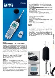
Graphic 1: Transmission of the silicon window.<br />
Radiant energy is absorbed/radiated from the surface of the blackened thermopile,<br />
creating a temperature difference between the centre of the thermopile (hot junction)<br />
and the body of pyrgeometer (cold junction). The temperature difference between hot<br />
and cold junction is converted into Potential Difference thanks to the Seebeck effect.<br />
If the pyrgeometer temperature is higher than the radiant temperature of the portion<br />
of sky framed by the pyrgeometer, the thermopile will irradiate energy and the output<br />
signal will be negative (typical situation of clear sky) vice versa if the pyrgeometer<br />
temperature is lower than that portion of sky framed, the signal will be positive<br />
(typical situation of cloudy sky).<br />
Therefore, for the calculation of infrared radiation (E FIR ↓) at ground level, besides<br />
the thermopile output signal, is necessary to know the T temperature of the<br />
pyrgeometer, as reported under the formula 1:<br />
E<br />
FIR<br />
term. B<br />
4<br />
↓= E + σT<br />
1<br />
Where:<br />
E term = net radiation (positive or negative) measure by the thermopile<br />
[W m -2 )], the value is calculated by the sensitivity of the instrument (C)<br />
[μV/ (W m - 2 ) ] and by the output signal (U emf ) from formula 2;<br />
- 2 -
E<br />
term = .<br />
U<br />
emf<br />
C<br />
2<br />
σ = Stefan-Bolzmann constant (5.6704x10 -8 W m -2 K -4 );<br />
T B = pyrgeometer temperature (K), obtained by the reading of the NTC (10kΩ)<br />
resistance. In the manual (Table 1) is reported the resistance value according to the<br />
temperature for values included between -25°C and +55°C.<br />
The first term of the formula 1 represent the net radiation, that is to say the difference<br />
between ground infrared radiation and the pyrgeometer emission, while the second<br />
term is the radiation emitted by an object (assuming emissivity ε=1) at T B<br />
temperature.<br />
3 Installation and mounting of the pyrgeometer for the infrared<br />
radiation measure:<br />
Before installing the pyrgeometer you need to load the cartridge containing silica gel<br />
crystals. The silica gel has the function of absorbing humidity present inside the<br />
instrument; this humidity can lead to condensation on the inner surface of the silicon<br />
window. While loading silica gel crystals, avoid touching it with wet hands. The<br />
operations to perform (as much as possible) in a dry place are:<br />
1- unscrew the three screws that fix the white screen<br />
2- unscrew the Silica gel cartridge by using a coin<br />
3- remove cartridge perforated cap<br />
4- open the envelope (included with the pyrgeometer) containing the silica gel<br />
5- fill the cartridge with silica-gel crystals<br />
6- close the cartridge with his cap, making sure that the O-ring seal is positioned<br />
correctly<br />
7- screw the cartridge into the body of the pyrgeometer with a coin<br />
8- make sure that the cartridge is firmly screwed (if not the duration of the crystals of<br />
silica gel is reduced)<br />
9- place the screen and screw it<br />
10- the pyrgeometer is ready to be used<br />
- 3 -
Figure 1 shows the operations necessary to fill the cartridge with the silica-gel<br />
crystals.<br />
• The <strong>LP</strong> <strong>PIRG</strong> <strong>01</strong> has to be installed in a location easily accessible for periodic<br />
cleaning of the silicon window. At the same time you should avoid buildings, trees or<br />
obstacles of any kind exceed the horizontal plane on which the pyrgeometer lies. In<br />
case this is not possible it is advisable to choose a location where the obstacles are<br />
lower than 10°.<br />
• Usually the instrument is placed so that the cable comes out from the side of the<br />
NORTH pole, when it is used in the NORTHERN hemisphere; from the side of the<br />
SOUTH pole when it is used in the SOUTHERN hemisphere according to the<br />
standard ISO TR99<strong>01</strong> and other WMO recommendations. In any case, it is preferable<br />
to comply with WMO/ISO recommendations also when the screen is used.<br />
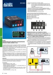
• For an accurate horizontal positioning, the pyrgeometer <strong>LP</strong> <strong>PIRG</strong> <strong>01</strong> is equipped<br />
with a spirit level, which adjustment is by two screws with lock nut that allows<br />
changing the pyrgeometer inclination. The fixing on a flat base can be performed by<br />
using two 6mm diam. holes and 65 mm wheelbase. In order to access the holes,<br />
remove the screen and re-place it back after mounting, see figure 2.<br />
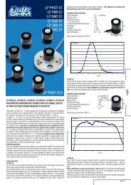
• The support <strong>LP</strong> S1 (figure 3), supplied upon request as an accessory, allows an<br />
easy mounting of the pyrgeometer support pole. The maximum diameter of the pole<br />
to which the bracket can be secured is 50 mm. To secure the pyrgeometer to the<br />
bracket, remove the screen by unscrewing the three screws, fix the pyrgeometer;<br />
once the installation is complete, fix the white screen back.<br />
- 4 -
D 6 mm<br />
Fixing holes<br />
65.0 mm<br />
79.0 mm<br />
165 mm<br />
50.0 mm<br />
Spirit Level<br />
<strong>LP</strong> <strong>PIRG</strong> <strong>01</strong><br />
2 1<br />
3 8 7<br />
58 mm<br />
4<br />
5<br />
6<br />
HD9906.47<br />
HD9906.46<br />
Figure 2<br />
HD 2003.77<br />
HD 2003.84<br />
HD 2003.85<br />
HD 2003.79<br />
HD 2003.83<br />
<strong>LP</strong> S1<br />
Pyrgeometer <strong>LP</strong> <strong>PIRG</strong> <strong>01</strong><br />
with <strong>LP</strong> S1<br />
HD 2003.77+77.1<br />
Figure 3<br />
- 5 -
4 Electrical Connections and requirements for electronic reading:<br />
• The pyrgeometer <strong>LP</strong> <strong>PIRG</strong> <strong>01</strong> does not need any power supply.<br />
• The instrument is equipped with an 8-poles M12 output<br />
• The optional cable, ending with a connector by one side, is made in PTFE<br />
resistant to UV and is provided with 7 wires plus braid (screen), the diagram<br />
with the correspondence between cable colours and connector poles is the<br />
following (figure 4):<br />
2 1<br />
8<br />
3 7<br />
4 5 6<br />
1<br />
2<br />
3<br />
4<br />
5<br />
6<br />
7<br />
8<br />
Figure 4<br />
Connector Function Colour<br />
1 V out (+) Red<br />
2 V in (-) Blue<br />
3 Instruement body ( ) White<br />
4<br />
Green<br />
NTC<br />
8 Black<br />
5 Shield Brown<br />
6<br />
7<br />
Not connected<br />
Figure 4: correspondence pin-function<br />
To measure the output signal from the thermopile (wires terminals 1-2) the<br />
pyrgeometer has to be connected to a data-logger or digital voltmeter (DVM).<br />
Typically the output signal from the pyrgeometer is | U emf |
<strong>LP</strong> <strong>PIRG</strong> <strong>01</strong><br />
Thermopile<br />
Case<br />
-<br />
+<br />
Surge - arrestor<br />
NTC<br />
blue<br />
2<br />
red<br />
1<br />
white<br />
3<br />
5<br />
brown<br />
(schield)<br />
green<br />
4<br />
black<br />
8<br />
Figure 5<br />
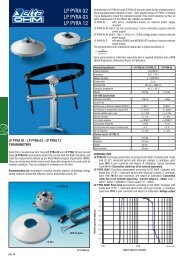
Under figure 6 you can see a typical example of connection:<br />
<strong>LP</strong> <strong>PIRG</strong> <strong>01</strong><br />
2 1<br />
8<br />
3 7<br />
4 5 6<br />
Probe output= µV/(W/m 2<br />
)<br />
Red [ 1]<br />
Blue [ 2]<br />
Brown[ 5]<br />
White [ 6]<br />
Datalogger<br />
or<br />
Converter/Amplifier<br />
with Vor mA output<br />
Green [ 4]<br />
Black [8]<br />
Probe<br />
internal<br />
temperature<br />
5 Maintenance:<br />
Figure 6: example of connection of pyrgeometer<br />
In order to ensure a high measurement accuracy, it is necessary to keep clean the<br />
silicon window, so the higher the frequency of cleaning, the best measurement<br />
accuracy will be. Cleaning can be done white cloth and water, if not possible, use<br />
pure ethyl alcohol. After cleaning with alcohol, it is necessary also to clean the<br />
window again with water only.<br />
Due to the high temperature fluctuations between day and night, it is possible that<br />
you get some condensation inside the pyrgeometer (especially on the silicon<br />
window); in this case the reading is wrong. To minimize condensation inside the<br />
pyrgeometer, a proper Silica gel cartridge is supplied with the instrument.<br />
The efficiency of silica-gel crystals decreases over time with the absorption of<br />
moisture. When crystals of silica gel are efficient their colour is yellow, while when<br />
gradually losing efficiency their colour becomes transparent; in order to replace them<br />
please refer to the instructions under paragraph 3. Silica gel typically lifetime goes<br />
- 7 -
from 4 to 12 months. Hail of particular intensity or dimension may damage the<br />
silicon window, therefore, after an intense storm with hail, it is recommended to<br />
check the status of the window.<br />
6 Calibration and measurements:<br />
According to the NTC R NTC [ohm] resistance it is possible to trace the pyrgeometer<br />
temperature (T b ) back by using the formula 3:<br />
1<br />
= a + b ⋅ log( R ) + c ⋅ log( R ) 3<br />
3<br />
T<br />
NTC<br />
NTC<br />
b<br />
Where:<br />
a=10297.2x10 -7 ;<br />
b=2390.6x10 -7 ;<br />
c=1.5677x10 -7 .<br />
Temperatura is expressed in Kelvin degrees.<br />
N.B. In table 1 you can get the values between -25°C and +58°C; in order to obtain<br />
the value in Kelvin degrees it is necessary to sum 273.15 to the value read in Celsius<br />
degrees.<br />
- 8 -
T<br />
[C]°<br />
R_ NTC<br />
[Ω]<br />
T<br />
[C]°<br />
R_ NTC<br />
[Ω]]<br />
T<br />
[C]°<br />
R_ NTC<br />
[Ω]<br />
-25 103700 3 25740 31 7880<br />
-24 98240 4 24590 32 7579<br />
-23 93110 5 23500 33 7291<br />
-22 88280 6 22470 34 7<strong>01</strong>6<br />
-21 83730 7 21480 35 6752<br />
-20 79440 8 20550 36 6499<br />
-19 75390 9 19660 37 6258<br />
-18 71580 10 18810 38 6026<br />
-17 67970 11 18000 39 5804<br />
-16 64570 12 17240 40 5592<br />
-15 61360 13 16500 41 5388<br />
-14 58320 14 15810 42 5193<br />
-13 55450 15 15150 43 5006<br />
-12 52740 16 14520 44 4827<br />
-11 5<strong>01</strong>80 17 13910 45 4655<br />
-10 47750 18 13340 46 4489<br />
-9 45460 19 12790 47 4331<br />
-8 43290 20 12270 48 4179<br />
-7 41230 21 11770 49 4033<br />
-6 39290 22 11300 50 3893<br />
-5 37440 23 10850 51 3758<br />
-4 35690 24 10410 52 3629<br />
-3 34040 25 10000 53 3505<br />
-2 32470 26 9605 54 3386<br />
-1 30980 27 9228 55 3386<br />
0 29560 28 8868 56 3271<br />
1 28220 29 8524 57 3161<br />
2 26950 30 8195 58 3055<br />
Table 1: values of NTC resistence according to the temperature.<br />
Once the pyrgeometer temperature in Kelvin degrees and the thermopile output<br />
signal are known U emf [μV], irradiation E FIR ↓ [W/m 2 ] is obtained by the formula 1:<br />
U<br />
emf<br />
4<br />
E ↓= + σ ⋅T<br />
FIR C B<br />
Where:<br />
C = pyrgeometer calibration factor [μV /(W/m 2 )] reported on the calibration report;<br />
σ = Stefan-Bolzmann constant (5.6704x10 -8 W m -2 K -4 ).<br />
- 9 -
Each pyrgeometer is individually calibrated at the factory and is distinguished by its<br />
calibration factor.<br />
Pyrgeometer calibration is performed outdoors, for comparison with a reference<br />
standard pyrgeometer calibrated by the Word Radiation Center (WRC).<br />
The two instruments are kept outdoors for some nights in the presence of clear sky.<br />
The data acquired by a data logger is then processed to obtain the calibration factor.<br />
To take full advantage of the <strong>LP</strong> <strong>PIRG</strong> <strong>01</strong> features, we recommend to perform the<br />
calibration every one, two years (the choice of calibration interval depends both on<br />
the accuracy to be achieved and on the installation location).<br />
7 Technical specifications:<br />
Typical sensitivity: 5-10 μV/(W/m 2 )<br />
Impedance:<br />
33 Ω ÷ 45 Ω<br />
Measuring range: -300;+300 W/m 2<br />
Field of view: 160°<br />
Spectral range: 5.5 μm ÷ 45 μm (50%)<br />
(transmission from the silica window)<br />
Working temperature: -40 °C ÷ 80 °C<br />
Dimensions: figure 2<br />
Weight:<br />
0.90 Kg<br />
- 10 -
Technical specifications according to ISO 9060<br />
Response Time:<br />
(95%)<br />
8 Purchasing codes<br />
PURCHASING CODES<br />
<strong>LP</strong> <strong>PIRG</strong> <strong>01</strong><br />
Pyrgeometer. Equipped with protection,<br />
silica-gel crystals cartridge, 2 richarges,<br />
level. 8-poles M12 connector and Report<br />
of Calibration ISO90<strong>01</strong>.<br />
<strong>LP</strong> S1 Kit made of bracket for mounting<br />
pyrgeometer <strong>LP</strong> <strong>PIRG</strong> <strong>01</strong> to a pole with<br />
diameter 50mm<br />
<strong>LP</strong> SP1<br />
<strong>LP</strong> SG<br />
HD2003.77<br />
HD2003.85K<br />
<strong>LP</strong> G<br />
Protection screen made in plastic UV<br />
resistant. LURAN S777K della BASF<br />
Cartridge for silica-gel crystals equipped<br />
with OR and cap<br />
Compass for positioning the pyrgeometer<br />
on a 40mm diameter tube<br />
Kit for fixing the pyrgeometer on a 40mm<br />
diam pole, with adjustable height<br />
(HD2003.84 – HD2003.85 – HD2003.79)<br />
Pack of 5 cartridges of silica gel crystals<br />
- 12 -