PRoal TIP SM< lLOEO t.f.Sl I r-------------, , ' 1002 F 20 ..[
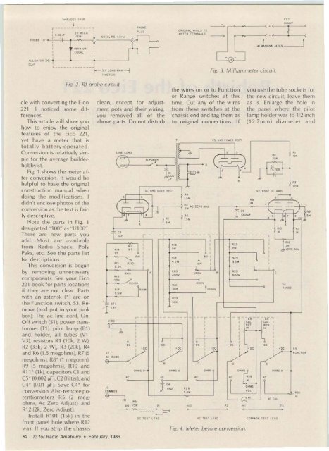
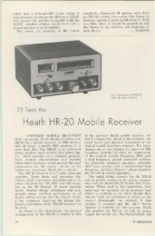
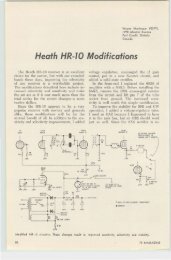
8100,8101 Cl00, C102 Cl01 CR100, CR101 Al00 R1 01 R102 R103 A,04 A,OS R106, 107 8 ' 00 5 101 "'00 Parts Li st s.c-vort transistor battery with connectors (battery holders optional) O .OO5-~ F. 5O-volt mica O .OO l·~F.50-volt mi ca 1N4oo5 or equivalent 6oo·piv,1·Amp diode lOOk, 114 W, 10% POI. 15k, 112 Watt, penei-mc unt type 15 meg, 114 Watt. 10% 1k, 1/4 Walt, 10% (can use old Rl0 or R11) 20 meg, 1/4 Watt, 10% or !2) 10 meg, 114 Walt, 10% in series 3.3k, 114 Watt, 10% 680 Ohms, 1/4 Walt, 10% toggle swi tch, OPST toggle switch, SPOT IC, National Semiconductor lM,J1 0H volt age follower non sw itch and is relocated on <strong>the</strong> chassis. Use insula ted hookup w ire for all wiring. l ead dress is not cr itical, but capacitors Cl 00. Cl 0l , and Cl 02 should be wired close to Ul00 Rl 0b and Rl07 can be m ounted o n Function sw itch 53. Break <strong>the</strong> w iring to R27 and R29 and insert <strong>the</strong>m in series. Rl0S is inserted from R30 to 53, deck E. Break wiring to R30 and put in series. Be sure to gro und <strong>the</strong> w ire which went to pi n 3 o n th e V2 (65N7) socket and decks D and Eon <strong>the</strong> Function sw itch. Theory <strong>of</strong> Operation C apac it o rs Cl OD and C102 bypass <strong>the</strong> battery p ower su pply. Diode s CR102 and CR103 prevent an overvoltage condit io n if you are probing a large voltage while <strong>the</strong> meter is switched to a low-voltage range. They limit vo lt age on Ul00, pin 3 to ± 9 .0 voltsde. Resistor Rl00 limits current into CR102 and CR103 and forms part <strong>of</strong> <strong>the</strong> protective circu it ry . Ca pac itor ( 101 keeps any ac out <strong>of</strong> Ul00's input. Its val ue is not critical except increa sing its value will increase <strong>the</strong> measuring ti me. Potentiometer R101 is <strong>the</strong> new Zero Adjust pot. D iodes CR100 and CR101 replace <strong>the</strong> original 6H6 diode circuit. They shou ld be m ount switch 5101 (1.5-V Batterv Test sw itch) This switch does two things-it f ills a vacant hole. bu t more important. it allows you to te st <strong>the</strong> ohm meter 1.S-volt battery. Break <strong>the</strong> w ire from th e Functio n switch to Jl (dc jack) and wire in this sw itch. Rl02, <strong>the</strong> l S-megohm resistor, can be mounted on Range sw itch 52 . M ount sw itch 5100 in <strong>the</strong> hole where <strong>the</strong> original O n Off sw itc h (51) w as located. Batteries B100 and Bl 01 may be mounted in special clips avai lable for <strong>the</strong>m or m ounted to <strong>the</strong> chassis with cable ties o r strapping tape. Use connectors that m at e <strong>the</strong>m or make your own from d iscarded 9 0-volt bat teries. Batteries need replacing periodically, so so ldering <strong>the</strong>m is not advisable. Ul00 can be so ldered into one <strong>of</strong> <strong>the</strong> existing tube socke ts or pu sh out one o f <strong>the</strong> transform er grommets and in sert a round nylon 8-pin IC socket in <strong>the</strong> hole and wire to <strong>the</strong> socket. Al l remaining parts m ay be w ired to <strong>the</strong> two remaining sockets or mount to so me 3-lug solder st rips mounted o n <strong>the</strong> chassis A perforated Vectorboard " could al so be u sed . This part <strong>of</strong> <strong>the</strong> conversion is m ostly left up to <strong>the</strong> hobbyi st's ingem ntv. ( 4 was on th e Funcat least 600-piv , 1 -A m p and chassis and a senous types. CR100 clips <strong>the</strong> negative ...hock could result. A sug half <strong>of</strong> <strong>the</strong> cycle to gested method is to use a g rou nd a fte r cou plin g 6.3-V -a c tran sformer and through capacitor C3. CR101 . calibrate <strong>the</strong> meter on <strong>the</strong> Rl04, and R103 "steer" <strong>the</strong> 10-V -ac ran ge, com pa ring positive ha lf <strong>of</strong> <strong>the</strong> cycle to <strong>the</strong> reading with a known <strong>the</strong> Function switch and good meter. Range sw itch circuit as dc A lways turn this meter <strong>of</strong>f input does C4 bypasses any when not using it. as th e stray ac to ground. LM-310H draw s about 4 rnA and will consume <strong>the</strong> ba t- Calibration teries in a period <strong>of</strong> time. An With unit power <strong>of</strong>f and LE D Power On ind icat or <strong>the</strong> 5101 l .5-V Battery Test would consume 20 rnA from sw itch ...et to De Read, ad- <strong>the</strong> power supply, so it w as just <strong>the</strong> mechanical zero not part <strong>of</strong> this co nvers ion sc rew o n <strong>the</strong> meter until <strong>the</strong> Ano<strong>the</strong>r usefu l appliesneedle points to zero. Turn non in ham radio for this <strong>the</strong> 51 00 meter p owe r convers ion is to u se an rf sw itch on and ad just <strong>the</strong> probe into <strong>the</strong> ac input and Zero Adju st control (R101 ) measure relative power o utuntil little or no change oc- pu t and a nte n na f iel d cu rs when <strong>the</strong> Func t ion stren gth. A short piece <strong>of</strong> switch goe s from +dc to wire or a clip lead on th e - dc w ith no probe input. end o f an rf probe will pick Probe a known dc vo ltage up enough rf energy to give and adjust <strong>the</strong> De Cal con- a good reading. <strong>Eico</strong> had a tro] for <strong>the</strong> correct m eter model PRF -25 probe availread ing. Po sition <strong>the</strong> 1.5-V ab le for this V1VM, or a sim - Battery Test sw itch to read ple probe may be rnade with <strong>the</strong> ohm meter battery on a 1N48 diode. a 002-jJF, <strong>the</strong> S-V sca le. You should 600·V capacitor. and a read about 1.5 volts on a 20-megohm, 1!2-W att resisnew battery. Position it back tor in a shielded tube or ento De Read . Next. switch th e closure. See Fig. 2. Func t ion switch t o <strong>the</strong> lf vou strll need a rrnlltam- Ohms position and set <strong>the</strong> meter, <strong>the</strong> basic movement Ohms Adjust control on <strong>the</strong> here is 0 -1 rnA dc full scale. front panel so <strong>the</strong> meter Mount a DPDT switch on reads infinity resistance (on <strong>the</strong> front panel and wire <strong>the</strong> left side <strong>of</strong> scale) w ith <strong>the</strong> re- meter term inals to <strong>the</strong> comsist ance probe open -err - m an cont acts. Wire two cu ited (not sho rted to <strong>the</strong> banana jack s to <strong>the</strong> normalground probe). To uching lv-clos ed co ntacts and con<strong>the</strong>se probes toge<strong>the</strong>r will nect <strong>the</strong> two o riginal meter bring <strong>the</strong> needle to read wires to <strong>the</strong> normally-open zero Ohm... on <strong>the</strong> right side contact s (see Fig. 3). The <strong>of</strong> <strong>the</strong> meter scale. b anana jacks could be Never leave <strong>the</strong> meter in mounted o n <strong>the</strong> back <strong>of</strong> <strong>the</strong> <strong>the</strong> Ohms position or 5101 in cab ine t. O f course. <strong>the</strong> main <strong>the</strong> 1.S-V Battery Test posi- on-<strong>of</strong>f sw itc h sta ys <strong>of</strong>f to use tion as <strong>the</strong> latter d isables <strong>the</strong> t he l-mA function. By expermeter from reading dc and imenting w ith resistor shunts <strong>the</strong> first is normal proce- ac ross <strong>the</strong> banana jacks, this dure. The battery cou ld l-mA ran ge ca n be extended d rain over a few months. Fi- to seve ral Amps. Start with na lly, put <strong>the</strong> Fu nc tion about 90 Ohms and go as sw itch in <strong>the</strong> Ac position low as 0 .1 Ohms and comand adjust <strong>the</strong> Ac Cal pot p a re t he reading with until a known ac vo ltage ano<strong>the</strong>r milliammeter in reads correctly on <strong>the</strong> m e- series with th is meter beter. Caut io n: Do not u se <strong>the</strong> tween a de power source ac l ine to calibrate this me- and a load With <strong>the</strong> proper ter as one side <strong>of</strong> <strong>the</strong> l ine shunt. this meter sho uld w ill alw ays be on <strong>the</strong> panel track <strong>the</strong> known meter. . 73 for Radio Amateurs . February, 1986 53