Heath SB-610 Monitor Scope Modifications - Nostalgic Kits Central
Heath SB-610 Monitor Scope Modifications - Nostalgic Kits Central
Heath SB-610 Monitor Scope Modifications - Nostalgic Kits Central

You also want an ePaper? Increase the reach of your titles
YUMPU automatically turns print PDFs into web optimized ePapers that Google loves.
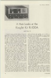
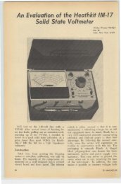
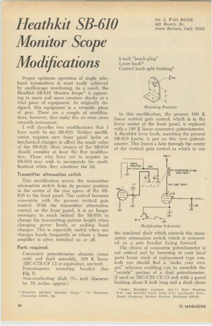
<strong>Heath</strong>kit <strong>SB</strong>-<strong>610</strong>Ian A . Webb K6SDE432 Rosario Dr.Santa Barbara, Calif. 93105<strong>Monitor</strong> <strong>Scope</strong>Modi icationsProper optimum operation of single sidebandtransmitters is most easily achievedby oscilloscope monitoring. As a result, the<strong>Heath</strong>kit <strong>SB</strong>-61O <strong>Monitor</strong> <strong>Scope</strong>' is appearingin more and more amateur shacks as avital piece of equipment. As originally designed,this eq uipment is a versatile p ieceof gear. T here arc a couple of modifications,however, that make this an even moreversatile instrument.I will describe two modifications that Ihave made to my <strong>SB</strong>-61O. Neither modificationrequires new front panel holes ormechanical changes to affect the resale valueof the SIl-6 1O. Most owners of th e <strong>SB</strong>-61Oshould consider at least the first m odification.Those who have yet to acquire an<strong>SB</strong>-<strong>610</strong> may wish to incorporate the modifications when they construct the kit.Transmitter attenuation switchThis modification moves the transmitterattenuation switch from its present positionin the center of th e rear apron of th e <strong>SB</strong><strong>610</strong> to the Irorit panel. The control becomesconcentric with the present vertical gaincontrol. \ Vith the transmitter attenuationcontrol 011 the front panel, it is no longernecessary to reach behind the SR-<strong>610</strong> tochange the transmitting pattern height whenchanging power levels or making bandchanges, This is especially useful when onechanges hands frequently or where a linearamplifier is often switched on or off,Paris required:Concentric potentiometer element (outerunit) and shaft asscmblv . , 100 K linear(IRC-CT S CF 13 or equivalent, see text)Potentiometer mounting bracket (SecF ig. 1)Non-conducting shaft O'iG inch diameterby 10 inches approx.)jr" Hf'athkit ~ B· 6 10 :\lo n itor SCOllP," 7 3 JIa aaZhlt ,(l)('t'l'IlI!J('r ]9(6), 5 4,>< inch "hutch plug"Lever knob"Control knob split bushing',--'HORIZ.POSlTlON•Sl-C"-----t.Jlounting BrackettIn this modification, the presen t 100 Klinear vertical gain control, which is in thelower center of the front panel, is replacedwith a 100 K linear concentric potentiometer.A <strong>Heath</strong>kit lever knob, matching the present<strong>SB</strong>-6 IO knobs, is put on this new potcntiometer.This leaves a hole through the centerof th e vertical gain control in which to run280 V/ II (SEE TEXT)/'iJ, /"'"J,/L _ -'_....I 15K (S EE TEXT )~ RY, 53000HIliIS, 4.1MA1,- , VI8,' -J/odification Schematicf --- "j''--w_._---
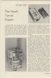
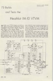
•% inch long which I cut to exactly fit the<strong>Heath</strong>kit lever knob.)Remove all three wires to the lugs of theold vertical gain control (AJ in the 5B-6IOmanual) and remove the old control andknobs keeping the wires in order so theymay be soldered to the new control. Beforemounting the new pot, be sure that theknob shaft will extend just far enough toallow you to m ount the new lever knob onit. Do any cutting of th e shaft before mountingthe potentiometer to prevent damage tothe front panel of the 5B-<strong>610</strong>. Mount thenew control and resolder the wires to thecorresponding lugs of the new control.Fabricate a bracket as shown in Fig. 1and refer to the photos to sec mountingdetails. (If you are lucky as I was, yourjunk box will yield a suitable b racket.) Unsolderth e wire from the coaxial connectorto th e lug 4 of switch BD, the transmitterattenuation switch, and unsolder the capacitorwhich runs from terminal strip G, lug5 to terminal 5 of switch BD. You can nowremove the switch from the hack apron. Ifyou wish, fill the empty hole in the backapron with a "hutch plug.". Mount the new mounting b racket in linewith the old hole in which the switch wasmounted. Allow enough room fo r the switchto bc remounted between th e new bracketand the h ack apron. Mount the switch andreattach the wire from the coaxial connectorto terminal 4 and the capacitor to terminal5 of the remounted switch. Orient the switchso this can he accomplished with the leastdifficulty. Be certain that no components sticklip far enough to interfere with the casewhen it is replaced over the <strong>Monitor</strong> <strong>Scope</strong>.Attach the shaft coupler to the switchshaft and insert the 3/16 inch non-conductingshaft extension from the fron t panel into thehole through the vertical gain control runningit back to th e shaft co upler. Care fullymove any parts that interfere with the shaft.The large .25 mfd capacitor near the shaftcoupler between the tube socke t (\'3) andthe terminal strip G may need to be relocatedto provide suffi cient clearance. A metallicshaft extension is not recommended dueto the possibility of accidental contact withparts on the chassis.When the shaft has been properly mated,mak e a small shim from a piece of scrapor tin can to red uce the ~ inch coupleron the switch to accep t the :;lg inch shaftextension. \ Vith the shaft in place measureAPRIL 196932 inch beyond the lever knob mounted onthe vertical gain control and remove andcut the shaft at this point. Mount the shaftfirm ly, tightening the coupler. Use the newsplit bushing inside the original knob removedfrom the vertical gain control tofi rmly fasten the knob onto the shaft ex tensionHush with th e lever knob.The 5B-6IO will now operate exactly asit di d originally. It is now possible to selectth e vertical gain when monitoring a receivedsignal using the lever knob and to changethe transmitter attenuation using the largeoriginal knob. It is no longer necessary toreach behind the 5B-61O each time the linearis turned on or off or each time you needattenuation changes when switching banos.Clamp ModificationThis modification should appeal to . thosepeople, myself included, who believe th atthe main virtue of the <strong>SB</strong>-<strong>610</strong> is th e monitoringof one's transmitted envelope usingthe internal sweep. If you use the internalTop V i t'IVsweep icithout also monitorin g received signalsduring standby periods, the trace of the5B-6IO will remain a static baseline of highintensity since the clamp circuit is inoperativein this mode. This can cause a burnedscope face if the intensity is h igh enoughfor good m onitoring of peaks in a brightlyilluminated room. I decided that I wouldlike to remove the trace from the scope face:m lomaticalIv when th e transmitter is turned-to standby. T his could be done using therelays that switch the rig from transmit toreceive, but since my rig is a transceiver43
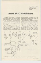
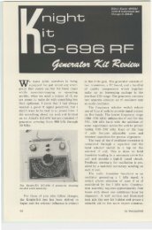
that I also use when mobile, this wouldinvolve additional connections to attach andremove each time I switched from b ase stationto mobile operation. Xly modification accomplishesthe clamping of the trace withno additional connections to the transmitteror receiver.Parts required:Capacitor, .05 rnfd, 50 voltsHesistors: 33K, ~ watt and resistor inseries with relay coil (see text)Sensitive plate relay, DPST, N.O., (LafayetteRadio 99H6093, DPDT, 5300 ohm,4.1 mn., 4 oz., shipping weight, $2.95,Lafayette Haclio, 11 1 Jericho Turnpike,Syosset, L.T. , N.Y. 11791 ) Sec text fordetails.The relay I used, was from my junkbox. Lacking a suitab le relay, the one listedin the list above is suggested. It may require ingenuity to mount some relays, buta small bit of epoxy will do wonders ifproperly applied.Fig. 4 shows the circuit modifica tions tobe made. The dark portions of the circuitare addi tional components or modifications.The clamp tube, VlB, is turned into a relayamplifier. Relay contacts are used to pullthe trace off the screen by shorting thehorizontal position control through a 33 Kresistor. A second set of contacts groundsthe grid of V3A to stop the sweep. If thesweep is not disabled, the left portion ofthe trace will still be on the screen. Pins 1and 2 of the front panel sweep control arejumpered so that the "pull for clamp" controlwill work in the internal sweep positionof the sweep control as well as in the othersweep positions. When this modification ismade, the SH-6IO will operate as originallydesigned in the RTTY and rf Trap positionsof the sweep switch. T he clamp will a lsowork in the internal (In t.) position of thesweep control when the "pull for clamp" controlis pulled out. The d amp switch mayhe pushed in so that received signals mayalso be monitored as originally designed.The .2 microfarad capacitor on terminalstrip H adjacent to tube socket VI ischanged to .05 microfarads to allow 1 to2 seconds before the trace leaves the screen.This capacitor need not be changed, hut thetime for the trace to leave the screen willbe in excess of ten seconds if it is notchanged. Remove the capacitor from stripH and replace it with the .05 mfd capacitorif you desire this change.44•Bottom ViewThe left hand lug of terminal strip U,near the chassis edge was originally unused.Remove the blue wire at pin 7 of VI andsolder it to this unused lug of terminalstrip U. On the back of the front panel,solder a jumper wire between lugs 1 and" of the sweep switch.Mount the plate relay in the space betweenthe tube socket VI, terminal stripU and the edge of the chassis. If your relaycan he mounted with screws as could myjunk box relay, that is fine; otherwise youmay have to use some ingenuity and p erhapssome epoxy to mount the relay.F rom one set of relay contacts (closedwhen the relay is operated) nm a wire to aconvenient ground point such as the mountinglug of terminal strip U. From the othercontact of the set, connect the 33 K resistorto the blue wire which you soldered to thepreviously unused lug of terminal strip Uncar the outside of the chassis.From the second set of contacts (alsoclosed when the relay is operated) run awire to ground. From the other contact ofthis set. run a wire to pin 9 of tube socketV3A which is the tube socket ncar the shaftextension. This set of contacts will nowground the grid of tube V3A when therelay is closed and stop the sweep.Run a wire from one end of the relaycoil to the 280 volt bus. I ran the wireto the junction of the 40 mfd capacitor;is K, 1 \V resistor; 1 K, J \V resistor;and 20 mfd capacitor. This is ncar the centerof the chassis on capacitor K, pin 3.Temporarily, attach the remaining endof the relay coil to pin 7 of VI througha resistor. (This resistor sho uld he nominally]5 K ohms for the relay in the parts list.)The resistor should be selected so that therelay used just pulls in reliably when the73 MAGAZINE
•clamp switch is pulled out, the <strong>SB</strong>-61O turnedon, and no rf signal is applied . In any event,the plate d issipation of the 6BN8 relay amplifiershould not exceed the maximum ratingof 1.7 watts. The total resistance of therelay coil plu s series resistor should be atleast 10 K. (If you use a junk b ox relay,measure th e voltage from cathode to plate.and the current through the tube when therelay is pulled) in. The product of the voltageand current- in amperes-sho uld notexceed 1.7.)This completes the wiring of the modification.Check the wiring against the schematicin Fig. 4. Carefully plug the <strong>SB</strong>-61Oin with it still out of the case and let itwarm up. Check to see if the relay operateswhen the "pull to clamp" switch is pulledout and the sweep switch is in any p osition.If the relay does not opera te, first recheckthe wiring to make sure it is correct. Ifthe wiring is correct and the relay will stillnot pull.in, reduce the value of the resistorfrom the relay coil to pin 7 of VI untilthe relay reliably pulls in. This will assurethat minimum plate dissipation occurs intube VI. \ Vhen this value is found, solder inthe resistor permanently.When the "pull to clamp" switch is pushedin, the relay should drop out. The tracewill then appear on the face of the <strong>SB</strong>-6 1Oand it should operate normally.Set the sweep switch to Inl. and applya small amount of transmitter rf to theconnector at the rear of the SIl-6IO whilethe "pull to clamp" switch is out , The relayshould release and the trace should appearto allow normal transmitted signal monitoring. If the trace does not appear and therelay drop out, increase the rf signal. Whenthe rf is removed by turning off the transmitter,the trace should di sappear after 1to 2 seconds. If the trace has not movedcompletely off the scope face, it may benecessary to decrease the value of the 33 Kresistor. If the sweep still continues whenthe trace is off screen, the grid of tubeV3A (pin 9) is not being shorted to groundthrough the relay.I have operated my <strong>SB</strong>-6IO 24 hours aday for days at a tim e and experiencedno difficulties. You must now remember totu rn off the power switch after operating,for you no longer sec the green trace onthe screen to remind you that the 5B-6IO ison.. .. K6S D E•,•-_.-.. ,• •THE BEST2 METERCONVERTERModel 407$34.95ppd.144·146 MHz In. 28·30 MHz o"tor 146-148 MHz with a second crystalA f u ll description of this fantastic con ver terwould fill t h is page, but you can take our wor dfor it (or those of h u nd r eds o f satisfied users)that it's t he best. The reason is s im ple--we usethree RCA dual Kate MOSFETs. one bipolar, and3 d iodes in the best circuit ever. Still n ot co n vinced ? Then sen d for o u r free catalog and g'et.the full description, plus photos and even thes chema t ic.Can't wait? Then se n d W I a postal money orderfor $3 4.95 a n d we' ll rush the 407 ou t to you.N OT E : T h e Mode l 407 is also ava ilable in anyfr-eque ncy combinatio n u p to 450 M H z (some athiR'h er p r ices ) na listed in our ca t a log.*New York City a nd State resid ents add local sa les ta...VANGUARD LABSDept. H , 196-23 Jamaica Ave. , Hollis, N.Y . 11423ARNOLD'S ENGRAVINGPersonalizedELECTRi CON·THE·AIRSIGNW ITH CAllW orks on110 VAC$12.95Metaltex Lapel 8ar - $1.50 Metaltex Tie Clip. $2 .25ENGRAVINGRldgewood. N.Y. 11227ARNOLD'S2041 Linden St.the permaflex key •• ""th .. t¥o;" I...., '" dn,ight 1..,,01 10.,.i" • pi..otl . .. 2 ,..ddl. d.lig".• gi , i"ot.. ,,~ choic. 01 ....tom..ticI.mi utom.tic'" ' blillht hl"d h yi"g.• UI. dir.ctly ""ith . "y b l".mitt• • 0.thrO"llh . " . I.ctron;c ...,.• •.• 8 . mp. gold diU,,".d ,il... . con tach.dj.." l rom O·.o bO· '" 5.50 gr.",' .• di.t incti... "t... ,..ddr., . r. of"'91led G.IO ""• •gl.... . poxy.• ca"in.t i. te g. ..g. poli,hocl chro"'.19 95 •••p,....It••I: 1.9 5 " .q. • 3 .75 " . ,..ddl.1. ort. "d 1.1.5", w.i,ht ..pp. I po" " d, ..... "..&can.• l ilicon. "'"" • • fo.t ~ . ot..bility. _ntl.ct-k or "'oO.• 100:( US ",..d. '" ll..... nt•..r 10. I y.. soItI..,. roMIlI onlyJames Research compan\1,dep'l: AR- K11 schermerhorn 51., broold n n. • 11201APRIL 1969 45