A Better Heathkit "Cantenna" - Nostalgic Kits Central
A Better Heathkit "Cantenna" - Nostalgic Kits Central
A Better Heathkit "Cantenna" - Nostalgic Kits Central

Create successful ePaper yourself
Turn your PDF publications into a flip-book with our unique Google optimized e-Paper software.
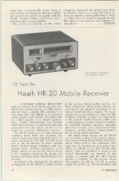
H. C. Sherrod W5ZG<br />
4715 Crockett Blvd.<br />
Gafwston TX 77550<br />
A <strong>Better</strong> <strong>Heathkit</strong> "Cantenna"<br />
- improved metering circuit for an old standby<br />
Update your dummy load.<br />
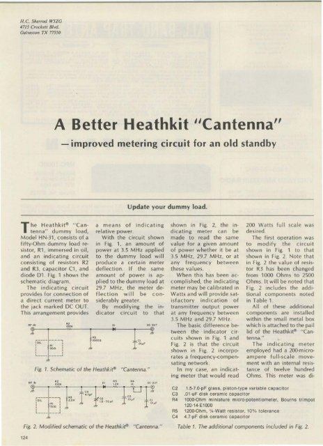
The He a thkit't " Ca n<br />
te nna" d ummy load,<br />
Model HN·31 . consists of a<br />
fifty-Ohm d ummy load resistor,<br />
R1 , imm ersed in o il,<br />
and an indicating circuit<br />
consis ting of resistors R2<br />
and R3, capacitor C1, and<br />
diode D1. Fig. 1 shows the<br />
schematic d iagram.<br />
The indicating ci rcuit<br />
provides for connection of<br />
a direct current me te r to<br />
the jack marked DC OUT.<br />
This arrangement provides<br />
"'-<br />
a means of indicating<br />
relative power.<br />
Wit h t he c ircuit shown<br />
in Fig. 1, a n am ount of<br />
power at 3.5 MHz applied<br />
to th e dummy load will<br />
prod uce a certain meter<br />
defle ction. If the sa me<br />
amount of power is applied<br />
to the dummy load at<br />
29.7 MH z, the meter deflection<br />
will be considerably<br />
greater.<br />
By modify ing the indicator<br />
ci rcuit to that<br />
..<br />
.<br />
..---- ---,<br />
I<br />
cr<br />
,~ - ,<br />
,00..'<br />
•<br />
"' ~Il'<br />
, L<br />
,<br />
J<br />
Fig. 1. Schematic of the Heat hk i~<br />
..<br />
" Cantenna."<br />
.. ec OVT<br />
"'<br />
"' '00'<br />
,.--- --.,<br />
'OIL ""<br />
: ~ll I<br />
, l<br />
..J,<br />
..<br />
," ..<br />
C2<br />
" cs<br />
C3<br />
r<br />
' ~·10 . '<br />
,0',,'<br />
R5<br />
C'<br />
T""<br />
'" " 1 °''''<br />
cr R'<br />
shown in Fig. 2. the ind<br />
icating meter can be<br />
made to read the same<br />
va lu e for a given amount<br />
of power whether it be at<br />
3.5 MHz, 29.7 MHz, or at<br />
any freq ue ncy between<br />
these values.<br />
When this has bee n accomplished,<br />
the ind icating<br />
meter may be calibrated in<br />
Watts and will prov ide satisfactory<br />
ind ica tio n of<br />
transmitter output power<br />
at any frequency between<br />
3.5 MHz and 29.7 MHz.<br />
The basic difference between<br />
the indicator circuits<br />
shown in Fig, 1 and<br />
Fig. 2 is that the circuit<br />
shown in Fig. 2 incorporate<br />
s a frequency-compensating<br />
network.<br />
In my case, an indicating<br />
meter tha t wou ld read<br />
200 Watts full scale was<br />
desired.<br />
The first operation was<br />
to modify the c ircuit<br />
shown in Fig. 1 to that<br />
show n in Fig. 2. Note that<br />
in Fig. 2 the va lue of res istor<br />
R3 has been changed<br />
from 1000 O hm s to 2500<br />
O hms. It will be noted that<br />
Fig. 2 incl udes the additiona<br />
l components noted<br />
in Table 1.<br />
All of these additional<br />
components a re installed<br />
within the small metal box<br />
which is attached to the pail<br />
lid of the Heathki~ "Cantenna."<br />
.<br />
The indicating meter<br />
employed had a 2()().microam<br />
pere fu ll -scale movement<br />
with an internal resista<br />
nce of twelve hundred<br />
Ohms. This meter was di-<br />
1.5-7.0-pF glass, piston-type variable capacitor<br />
.01-uF disk ceramic capacit or<br />
1Q()().Ohm mini ature rnrcro-potenucmeter, Bourns trimpot<br />
120-14-E1000<br />
12QO.Ohm, Y. ·Walt resistor, 10% tolerance<br />
4.7-pF disk ceramic capacitor<br />
Fig. 2. Modified schematic of the <strong>Heathkit</strong>'" " Cantenna." Table 1. The additional components included in Fig. 2.<br />
12'
- ee 00< "