3665: 4-channel Frequency Counter
3665: 4-channel Frequency Counter
3665: 4-channel Frequency Counter

Create successful ePaper yourself
Turn your PDF publications into a flip-book with our unique Google optimized e-Paper software.
CAMAC Equipment<br />
<strong>3665</strong><br />
4-<strong>channel</strong> <strong>Frequency</strong> <strong>Counter</strong><br />
CAMAC, Computer Automated<br />
Measurement And Control, is an<br />
IEEE-standard (583), modular,<br />
high-performance, realtime data<br />
acquisition and control system<br />
concept.<br />
Since 1969, CAMAC has been used in<br />
many thousands of scientific,<br />
industrial, aerospace, and defense<br />
test systems around the world.<br />
APPLICATIONS<br />
Jet aircraft engine testing<br />
Measurement of shaft speeds<br />
Pulse train monitoring<br />
<strong>Frequency</strong> measurement<br />
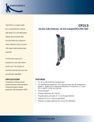
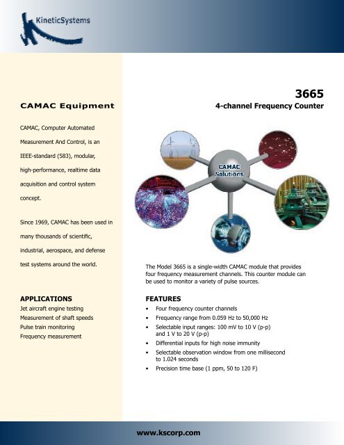
The Model <strong>3665</strong> is a single-width CAMAC module that provides<br />
four frequency measurement <strong>channel</strong>s. This counter module can<br />
be used to monitor a variety of pulse sources.<br />
FEATURES<br />
• Four frequency counter <strong>channel</strong>s<br />
• <strong>Frequency</strong> range from 0.059 Hz to 50,000 Hz<br />
• Selectable input ranges: 100 mV to 10 V (p-p)<br />
and 1 V to 20 V (p-p)<br />
• Differential inputs for high noise immunity<br />
• Selectable observation window from one millisecond<br />
to 1.024 seconds<br />
• Precision time base (1 ppm, 50 to 120 F)<br />
www.kscorp.com
GENERAL DESCRIPTION<br />
The Model <strong>3665</strong> is a single-width CAMAC module that provides four frequency<br />
measurement <strong>channel</strong>s. This counter module can be used to monitor<br />
a variety of pulse sources. Moreover, its unique circuitry allows the<br />
monitoring of a wide range of frequency (0.059 Hz to 50,000 Hz) without<br />
changing any module settings. For example, the RPM of an aircraft engine<br />
shaft can be monitored at full speed as well as when it coasts to a stop.<br />
Differential input circuits are used to provide high noise immunity.<br />
The input pulse stream for each <strong>channel</strong> is sampled during a user-selectable<br />
observation window. This window period is programmable from one<br />
millisecond to 1.024 seconds, and the selection is common to all <strong>channel</strong>s.<br />
At the end of each window period, 24 bits of data representing the time<br />
base count from the master clock as well as 24 bits representing the number<br />
of whole periods observed, are stored in the current value table (CVT)<br />
for that <strong>channel</strong>. If the period of the input pulse stream is longer than the<br />
window period, the window remains “open” until one whole period of the<br />
input signal is observed. If enabled, a LAM may be generated when any<br />
of the time base counters overflow. The CVT “scratchpad” memory can be<br />
read at any time from the Dataway, with the data from the latest observation<br />
being read. The frequency is calculated by the host computer using<br />
the following formula:<br />
<strong>Frequency</strong> = clock rate x whole input periods/time base counts<br />
The clock rate for the module is programmable to provide a tic rate of 1<br />
MHz or 10 MHz with a clock accuracy of 1 part per million (0.0001%) over<br />
a temperature range from 50 to 120 Fahrenheit. The availability of the two<br />
24-bit values (whole input period count and time base count) allows the<br />
module to monitor a wide range of pulse rates without changing any of<br />
the programmable settings. The counting accuracy depends on the time<br />
base accuracy as well as the monitoring resolution. The longer the observation<br />
window, the higher the accuracy. A 10 mS observation window<br />
will result in an accuracy of approximately 0.01% with a 1 MHz clock and<br />
0.001% with a 10 MHz clock. A 100 mS window will provide accuracies<br />
and order of magnitude better.<br />
The differential input range is selectable on a <strong>channel</strong>-by-<strong>channel</strong> basis<br />
(100 millivolts to 10 volts, peak-to-peak, or 1 volt to 20 volts, peak-topeak).<br />
Contact KineticSystems for other input voltage requirements.<br />
A separate input connector is provided for a “health check” signal, if<br />
desired. The input circuitry can be switched under program control from<br />
each of the <strong>channel</strong>s to that connector, providing a test of the operating<br />
characteristics of that <strong>channel</strong>.<br />
KineticSystems Company, LLC<br />
900 N. State St.<br />
Lockport, IL 60441-2200<br />
Toll-Free (US and Canada):<br />
phone 1-800-DATA NOW<br />
1-800-328-2669<br />
Direct:<br />
phone +1-815-838-0005<br />
fax +1-815-838-4424<br />
Email:<br />
mkt-info@kscorp.com<br />
ORDERING INFORMATION<br />
MODEL DESCRIPTION<br />
<strong>3665</strong>-Z1A 4-<strong>channel</strong> <strong>Frequency</strong> <strong>Counter</strong><br />
To find your local sales representative<br />
or distributor or to learn more about<br />
KineticSystems’ products visit:<br />
www.kscorp.com<br />
Updated December 14th, 2005<br />
Copyright © 2005 KineticSystems Company, LLC. All rights reserved.<br />
www.kscorp.com