CP213: 32/64/128-Channel, 16-bit PXI/cPCI ADC
CP213: 32/64/128-Channel, 16-bit PXI/cPCI ADC
CP213: 32/64/128-Channel, 16-bit PXI/cPCI ADC
- No tags were found...

You also want an ePaper? Increase the reach of your titles
YUMPU automatically turns print PDFs into web optimized ePapers that Google loves.
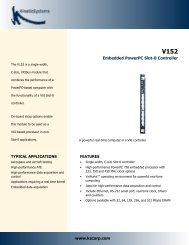
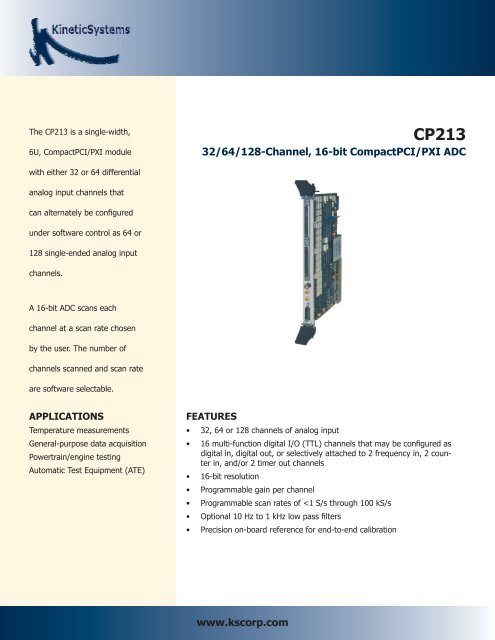
The <strong>CP213</strong> is a single-width,6U, CompactPCI/<strong>PXI</strong> module<strong>CP213</strong><strong>32</strong>/<strong>64</strong>/<strong>128</strong>-<strong>Channel</strong>, <strong>16</strong>-<strong>bit</strong> CompactPCI/<strong>PXI</strong> <strong>ADC</strong>with either <strong>32</strong> or <strong>64</strong> differentialanalog input channels thatcan alternately be configuredunder software control as <strong>64</strong> or<strong>128</strong> single-ended analog inputchannels.A <strong>16</strong>-<strong>bit</strong> <strong>ADC</strong> scans eachchannel at a scan rate chosenby the user. The number ofchannels scanned and scan rateare software selectable.APPLICATIONSTemperature measurementsGeneral-purpose data acquisitionPowertrain/engine testingAutomatic Test Equipment (ATE)FEATURES• <strong>32</strong>, <strong>64</strong> or <strong>128</strong> channels of analog input• <strong>16</strong> multi-function digital I/O (TTL) channels that may be configured asdigital in, digital out, or selectively attached to 2 frequency in, 2 counterin, and/or 2 timer out channels• <strong>16</strong>-<strong>bit</strong> resolution• Programmable gain per channel• Programmable scan rates of
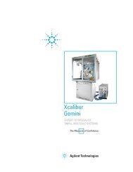
GENERAL DESCRIPTIONThe <strong>CP213</strong> is a single-width, 6U, CompactPCI/<strong>PXI</strong> module with either <strong>32</strong> or <strong>64</strong> differential analog input channels that can alternately beconfigured under software control as <strong>64</strong> or <strong>128</strong> single-ended analog input channels. A <strong>16</strong>-<strong>bit</strong> <strong>ADC</strong> scans each channel at a scan rate chosen bythe user. The number of channels scanned and scan rate are software selectable. Scans may be triggered from either the internal clock, oneof eight <strong>PXI</strong> backplane triggers, the <strong>PXI</strong> star trigger bus or an external SMB connector on the module front panel. Single and continuous scanoperations are supported. If single scan operation is chosen, an interrupt may be generated at the end of the scan.The <strong>CP213</strong> has programmable gain that can be set on a channel-by-channel basis. Gains of 1, 2, 5, 10, 20, 50, 100, 200, 500 and 1000 areavailable. On-board calibration is available on each channel for end-to-end calibration. Optional fixed, 2-pole, passive filters are available in a1, 2, 5 progression from 10 Hz to 1 kHz. Under software control, channels 1 and 33 may be configured as isothermal reference channels fortemperature measurement applications.In addition to the analog input channels, <strong>16</strong> multi-function digital I/O (TTL) channels are provided. Any of these channels may be configured asdigital in, digital out, or selectively attached to 2 frequency in, 2 counter in, and/or 2 timer out channels.On-board CalibratorAnalog InputTiming/ControlISOCh12:1Mux2:1MuxOptional2-poleFilterBufferMux<strong>16</strong>-<strong>bit</strong><strong>ADC</strong>PCIbusInterfaceCh<strong>64</strong> Diff / <strong>128</strong> SE2:1MuxOptional2-poleFilterPGACh1Ch<strong>16</strong>Multi-FunctionDigital I/OCounter/TimerBufferBASIC CIRCUIT OPERATIONThe <strong>CP213</strong> analog input channels are multiplexed to a high-speed programmable gain amplifier (PGA) that provides full-scale input ranges of±10 volts at a gain of 1 down to ±10 millivolts at a gain of 1000. The PGA supports scan rates up to 100 kHz at all gain settings. The analoginput channels may be configured as single-ended or differential inputs via software control. The number of channels scanned and the scanrate are also software programmable. A <strong>16</strong>-<strong>bit</strong> Successive Approximation Register (SAR) <strong>ADC</strong> samples the output of the PGA. Converted datafrom the <strong>ADC</strong> is stored in a <strong>32</strong>, <strong>64</strong> or <strong>128</strong> word memory, allowing “present value monitoring”. DMA capability allows converted data to be storedon host memory at the required data rates.The <strong>CP213</strong> also provides <strong>16</strong> multi-function digital I/O channels. Any of these channels may be configured as digital in, digital out, or selectivelyattached to 2 frequency in, 2 counter in, and/or 2 timer out channels. Two channels each of frequency in, counter in and timer out are provided.These channels operate at standard TTL levels.SOFTWAREThe <strong>CP213</strong> comes with a Plug and Play driver for configuring and using the device and application examples to illustrate its basic functionality.APPLICATION EXAMPLEThis and other tools, including their source code, are provided.www.kscorp.com
ANALOG INPUT CHANNELSNumber of analoginput channels:Input:Common ModeInput range:Differential ModeInput range:Input protection:Input impedence:Input coupling:Resolution:<strong>32</strong> differential / <strong>64</strong> single-ended or<strong>64</strong> differential / <strong>128</strong> single-ended(depending on option)±10 V±10 V±25 V continuous<strong>Channel</strong> + to ground = 1MΩ<strong>Channel</strong> - to ground = 1MΩDC<strong>16</strong>-<strong>bit</strong>sGain ranges: 1, 2, 5, 10, 20, 50, 100, 200, 500 and 1000Scan Rate (Per <strong>Channel</strong>):Internal frequency 0.00002<strong>32</strong> Hz to 100 kHzchoices:(in 4,294,967,296 steps)External sources: Front-panel SMB, TTL to 100 kHzDuty cycle: 50%Backplane source: 1 of 8 <strong>PXI</strong> backplane triggers or the<strong>PXI</strong> star trigger bus<strong>ADC</strong> Rate (Aggregate): 100 kHz (software programmable to20 kHz or 2 kHz for lower noise)Trigger Sources:External:Front panel SMB, negative-goingTTL signalBackplane:1 of 8 <strong>PXI</strong> backplane triggers or the<strong>PXI</strong> star trigger busTransfer Characteristics:IntegralNon-linearity (INL): 0.014% FSR maximum @ gain = 1-5000.04% FSR maximum @ gain = 1000Differentialnon-linearity (DNL): No missing codesInitial accuracy, RTI(Referred to input): After automatic calibrationAbsolute AccuracyDifferentialSingle-EndedGain = 1 ±2.2 mV ±2.2mVGain = 10 ±220 μV ±250 μVGain = 100 ±28 μV ±65 μVGain = 1000 ±15 μV ±55 μVOffset stability, RTI: ±12 μV/°C maximum @ gain = 1000Gain stability: ±18 ppm/°C maximum @ gain < 100±60 ppm/°C maximum @ gain 100-500±150 ppm/°C maximum @ gain = 1000Common moderejection:75 dB minimumNoise, RTI:5 μV rms @ gain = 1000, <strong>ADC</strong> rate = 2 kHz<strong>Channel</strong>-to-channelcrosstalk:Analog inputconnector type(s):14 μV rms @ gain = 1000, <strong>ADC</strong> rate = 20 kHz-90 dB1(2)- 68P High Density, 2-pin LEMO(for external calibration input)MULTI-FUNCTION DIGITAL I/O CHANNELSNumber of multi-function <strong>16</strong> digital I/O channels (channels maydigital I/O channels: be configured as digital in, digital out orselectively attached to 2 frequency in,2 counter in, and/or 2 timer out channels)I/O type:Single-ended TTLDirection control:YesInput termination:Pulled-upInput switching threshold:“0” Level: 0.8 V maximum“1” Level: 2 V minimumOutput voltage level:“0” Level: 0.4 V maximum (Iout = 2.5 mA)“1” Level: 2.7 V minimum (Iout = 2.5 mA)Low level output current: 24 mA, maximumHigh level output current: -24 mA, maximumInput current:±20 μAFrequency channels (2):Frequency range: 0.06 Hz to 1 MHzWindow period:1 mSCounter channels (2):Counter size:<strong>32</strong>-<strong>bit</strong>sTimer channels (2):Timer size:<strong>32</strong>-<strong>bit</strong>sDigital I/O connector type: 1- 26P Subminiature D connectorPOWERPower Requirements: With Filters Without Filters+5 V: 3740 mA* 1850 mA*+3.3 V: 350 mA 350 mA+12 V: 800 μA 800 μA-12 V: 800 μA 800 μA* The +5 V power requirement listed is for no-load. For each digitalI/O channel sourcing current, add that amount to the no-load power todetermine the total +5 volt requirement.ENVIRONMENTAL AND MECHANICALTemperature range:Operational:0°C to +50°CStorage:-25°C to +75°CRelative humidity: 0 to 85%, non-condensing to 40°CCooling requirements: 10 CFMDimensions: 233.35 mm x <strong>16</strong>0 mm (6UCompactPCI/<strong>PXI</strong> module)Front-panel potential: Chassis groundTechnical specifications contained within this publication are subject to change without notice.www.kscorp.com
GENERAL DESCRIPTIONRELATED PRODUCTSModel 5868-B001 Shorting Connector for <strong>CP213</strong>Model 5868-Bxyz Cable: 68S High Density to UnterminatedModel 5868-Dxyz Cable: 68S High Density to 68P High DensityModel 5868-Exyz Cable: 68S High Density to 68S High DensityModel 5857-Cxyz Cable: 2-contact LEMO to UnterminatedModel 5857-Dxyz Cable: 2-contact LEMO to 2-contact LEMOModel 5857-Gxyz Cable: 2-contact LEMO to BNC; shieldedModel 5826-Bxyz Cable: 26S Subminiature D to UnterminatedModel T910-Axyz Cable: SMB to SMB; shieldedModel T910-Bxyz Cable: SMB to BNC; shieldedModel T910-Cxyz Cable: SMB to UnterminatedModel 5926-Z1A 26S Subminiature D Mating Connector; solder cupchangeModel V765-ZA11 Rack-mount Termination PanelModel V792-ZA11 Rack-mount Isothermal Termination PanelORDERING INFORMATIONModel <strong>CP213</strong>-AA11 <strong>16</strong>-<strong>bit</strong> Scanning <strong>ADC</strong>, No Filters,Programmable <strong>32</strong>-ch Differential/<strong>64</strong>-ch Single-EndedModel <strong>CP213</strong>-ABB1 <strong>16</strong>-<strong>bit</strong> Scanning <strong>ADC</strong>, 10Hz Filters, <strong>32</strong>-chDifferentialModel <strong>CP213</strong>-AEB1 <strong>16</strong>-<strong>bit</strong> Scanning <strong>ADC</strong>, 100Hz Filters, <strong>32</strong>-chDifferentialModel <strong>CP213</strong>-AHB1 <strong>16</strong>-<strong>bit</strong> Scanning <strong>ADC</strong>, 1kHz Filters, <strong>32</strong>-chDifferentialModel <strong>CP213</strong>-ABC1 <strong>16</strong>-<strong>bit</strong> Scanning <strong>ADC</strong>, 10Hz Filters, <strong>64</strong>-chSingle-EndedModel <strong>CP213</strong>-AEC1 <strong>16</strong>-<strong>bit</strong> Scanning <strong>ADC</strong>, 100Hz Filters, <strong>64</strong>-chSingle-EndedModel <strong>CP213</strong>-AHC1 <strong>16</strong>-<strong>bit</strong> Scanning <strong>ADC</strong>, 1kHz Filters, <strong>64</strong>-chSingle-EndedModel <strong>CP213</strong>-BA11 <strong>16</strong>-<strong>bit</strong> Scanning <strong>ADC</strong>, No Filters,Programmable <strong>64</strong>-ch Differential/<strong>128</strong>-ch Single-EndedModel <strong>CP213</strong>-BBB1 <strong>16</strong>-<strong>bit</strong> Scanning <strong>ADC</strong>, 10Hz Filters, <strong>64</strong>-chDifferentialModel <strong>CP213</strong>-BEB1 <strong>16</strong>-<strong>bit</strong> Scanning <strong>ADC</strong>, 100Hz Filters, <strong>64</strong>-chDifferentialModel <strong>CP213</strong>-BHB1 <strong>16</strong>-<strong>bit</strong> Scanning <strong>ADC</strong>, 1kHz Filters, <strong>64</strong>-chDifferentialModel <strong>CP213</strong>-BBC1 <strong>16</strong>-<strong>bit</strong> Scanning <strong>ADC</strong>, 10Hz Filters, <strong>128</strong>-chSingle-EndedModel <strong>CP213</strong>-BEC1 <strong>16</strong>-<strong>bit</strong> Scanning <strong>ADC</strong>, 100Hz Filters, <strong>128</strong>-ch Single-EndedModel <strong>CP213</strong>-BHC1 <strong>16</strong>-<strong>bit</strong> Scanning <strong>ADC</strong>, 1kHz Filters, <strong>128</strong>-chSingle-Ended900 N. State St.Lockport, IL 60441-2200Toll-Free (US and Canada):phone 1-800-DATA NOW1-800-<strong>32</strong>8-2669Direct:phone +1-815-838-0005fax +1-815-838-4424Email:mkt-info@kscorp.comTo find your local sales representativeor distributor or to learn more aboutKineticSystems’ products visit:www.kscorp.comSpecifications contained within this data sheet are subject to change without notice.Updated January 15, 2009Copyright © 2009 DynamicSignals, LLC. All rights reserved.www.kscorp.com