QUANTUM R-4000 - Pride Mobility Products
QUANTUM R-4000 - Pride Mobility Products
QUANTUM R-4000 - Pride Mobility Products

You also want an ePaper? Increase the reach of your titles
YUMPU automatically turns print PDFs into web optimized ePapers that Google loves.
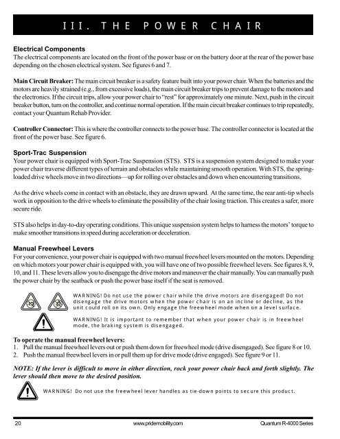
III. THE POWER CHAIR<br />
Electrical Components<br />
The electrical components are located on the front of the power base or on the battery door at the rear of the power base<br />
depending on the chosen electrical system. See figures 6 and 7.<br />
Main Circuit Breaker: The main circuit breaker is a safety feature built into your power chair. When the batteries and the<br />
motors are heavily strained (e.g., from excessive loads), the main circuit breaker trips to prevent damage to the motors and<br />
the electronics. If the circuit trips, allow your power chair to “rest” for approximately one minute. Next, push in the circuit<br />
breaker button, turn on the controller, and continue normal operation. If the main circuit breaker continues to trip repeatedly,<br />
contact your Quantum Rehab Provider.<br />
Controller Connector: This is where the controller connects to the power base. The controller connector is located at the<br />
front of the power base. See figure 6.<br />
Sport-Trac Suspension<br />
Your power chair is equipped with Sport-Trac Suspension (STS). STS is a suspension system designed to make your<br />
power chair traverse different types of terrain and obstacles while maintaining smooth operation. With STS, the springloaded<br />
drive wheels move in two directions—up for rolling over obstacles and down when encountering transitions.<br />
As the drive wheels come in contact with an obstacle, they are drawn upward. At the same time, the rear anti-tip wheels<br />
work in opposition to the drive wheels to eliminate the possibility of the chair losing traction. This creates a safer, more<br />
secure ride.<br />
STS also helps in day-to-day operating conditions. This unique suspension system helps to harness the motors’ torque to<br />
make smoother transitions in speed during acceleration or deceleration.<br />
Manual Freewheel Levers<br />
For your convenience, your power chair is equipped with two manual freewheel levers mounted on the motors. Depending<br />
on which motors your power chair is equipped with, you will have one of two possible freewheel levers. See figures 8, 9,<br />
10, and 11. These levers allow you to disengage the drive motors and maneuver the chair manually. You can manually push<br />
the power chair by the seatback or push the power base itself if the seat is removed.<br />
WARNING! Do not use the power chair while the drive motors are disengaged! Do not<br />
disengage the drive motors when the power chair is on an incline or decline, as the<br />
unit could roll on its own. Only engage the freewheel mode when on a level surface.<br />
WARNING! It is important to remember that when your power chair is in freewheel<br />
mode, the braking system is disengaged.<br />
To operate the manual freewheel levers:<br />
1. Pull the manual freewheel levers out or push them down for freewheel mode (drive disengaged). See figure 8 or 10.<br />
2. Push the manual freewheel levers in or pull them up for drive mode (drive engaged). See figure 9 or 11.<br />
NOTE: If the lever is difficult to move in either direction, rock your power chair back and forth slightly. The<br />
lever should then move to the desired position.<br />
WARNING! Do not use the freewheel lever handles as tie-down points to secure this product.<br />
20 www.pridemobility.com Quantum R-<strong>4000</strong> Series