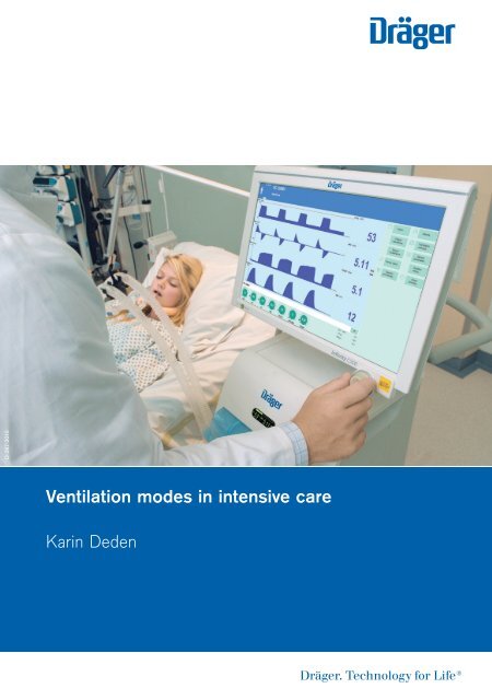
Ventilation Modes in Intensive Care
This brochure intends to facilitate the move from the old to the new nomenclature. For this reason, the properties and control principles of the individual ventilation modes are briefly outlined. The focus of the mode descriptions is the intensive care ventilation for adults, pediatric patients and neonatal patients. For a precise comparison of the designations, the brochure concludes with a comparison of the ventilation modes in the previous and the new nomenclature. The comparison of the designations is given for the intensive care ventilation of adults and neonatal patients as well as for anesthesia.
This brochure intends to facilitate the move from the old to the new nomenclature. For this reason, the properties and control principles of the individual ventilation modes are briefly outlined. The focus of the mode descriptions is the intensive care ventilation for adults, pediatric patients and neonatal patients. For a precise comparison of the designations, the brochure concludes with a comparison of the ventilation modes in the previous and the new nomenclature. The comparison of the designations is given for the intensive care ventilation of adults and neonatal patients as well as for anesthesia.

Create successful ePaper yourself
Turn your PDF publications into a flip-book with our unique Google optimized e-Paper software.
D-287-2010<br />
<strong>Ventilation</strong> modes <strong>in</strong> <strong>in</strong>tensive care<br />
Kar<strong>in</strong> Deden
Important note<br />
This brochure does not replace the <strong>in</strong>structions for use. Prior to us<strong>in</strong>g a ventilator the<br />
correspond<strong>in</strong>g <strong>in</strong>structions for use must always be read and understood.
<strong>Ventilation</strong> modes <strong>in</strong> <strong>in</strong>tensive care<br />
Kar<strong>in</strong> Deden
VENTILATION MODES IN INTENSIVE CARE |<br />
CONTENTS<br />
HEADQUARTERS<br />
Drägerwerk AG & Co. KGaA<br />
Moisl<strong>in</strong>ger Allee 53–55<br />
23558 Lübeck, Germany<br />
www.draeger.com
04| 05<br />
CONTENTS<br />
Important note 02<br />
Preface 06<br />
Introduction 09<br />
Mechanical ventilation 11<br />
Volume-controlled ventilation 18<br />
AutoFlow 20<br />
VC-CMV 22<br />
VC-AC 24<br />
VC-SIMV 26<br />
VC-MMV 28<br />
Pressure-controlled ventilation 30<br />
Volume guarantee 32<br />
PC-CMV 34<br />
PC-AC 36<br />
PC-SIMV 38<br />
PC-BIPAP 40<br />
PC-APRV 42<br />
PC-PSV 44<br />
Spontaneous/assisted ventilation 46<br />
SPN-CPAP/PS 48<br />
Variable PS 50<br />
SPN-CPAP/VS 52<br />
SPN-PPS 54<br />
Specific neonatal ventilation modes 56<br />
SPN-CPAP 58<br />
PC-HFO 60<br />
PC-MMV 62<br />
Extended ventilation sett<strong>in</strong>gs 64<br />
Nomenclature comparison 66<br />
Glossary 68<br />
References 70
VENTILATION MODES IN INTENSIVE CARE |<br />
PREFACE<br />
Preface<br />
TOWARDS A CLASSIFICATION FOR VENTILATION<br />
In 1977, Steven McPherson wrote the first popular book on ventilation<br />
equipment <strong>in</strong> the USA. <strong>Ventilation</strong> was discussed on 65 percent of the pages,<br />
but only 3 ventilation modes were expla<strong>in</strong>ed <strong>in</strong> detail: “controlled”, “assisted”<br />
and “spontaneous breath<strong>in</strong>g”. Some modes were not mentioned <strong>in</strong> the<br />
specification tables for ventilators <strong>in</strong> the book. Instead, the book focused on<br />
specific drive mechanisms and configurations as well as on how configurations<br />
could be comb<strong>in</strong>ed <strong>in</strong>to identifiable operat<strong>in</strong>g modes. The description of<br />
a ventilator <strong>in</strong> the book was, for example, ak<strong>in</strong> to an “… electrically driven<br />
rotat<strong>in</strong>g piston, double circuit, timed, time and volume limited controller<br />
…”. It must be taken <strong>in</strong>to account that the concept of “IMV” (Intermittent<br />
Mandatory <strong>Ventilation</strong>) had only been <strong>in</strong>vented four years earlier.<br />
The seventh edition of McPherson’s ventilator book was published <strong>in</strong> 2004.<br />
Interest<strong>in</strong>gly, about two thirds of the book are still dedicated to the topic of<br />
ventilation. In this edition, only 22 ventilation modes are described on 19 pages.<br />
However, on the subsequent pages where specific ventilators are described,<br />
93 different ventilation modes are mentioned. These are, however, not 93<br />
different modes. In many <strong>in</strong>stances, different names are used for identical<br />
modes (e.g. the pressure control ventilation plus adaptive pressure ventilation<br />
<strong>in</strong> the Hamilton Galileo corresponds to the pressure regulated volume control<br />
<strong>in</strong> the Maquet Servo 300), and <strong>in</strong> some cases, the same name is used for<br />
different modes (assist/control <strong>in</strong> the Puritan Bennett 840 is a k<strong>in</strong>d of<br />
volume-controlled ventilation, whilst assist/control <strong>in</strong> the Bear Cub<br />
ventilator for <strong>in</strong>fants is a k<strong>in</strong>d of pressure-controlled ventilation).<br />
As <strong>in</strong> many other fields, the technical complexity has <strong>in</strong>creased significantly<br />
<strong>in</strong> ventilation. Today modern ventilators might feature more than two dozen<br />
modes; some even utilize computer-assisted artificial <strong>in</strong>telligence. With<strong>in</strong> a<br />
s<strong>in</strong>gle human generation, ventilators have spanned approximately 5 generations
06|07<br />
<strong>in</strong> development. What has not been developed is a standardized system<br />
sufficiently describ<strong>in</strong>g this technical complexity. This causes four ma<strong>in</strong><br />
problems: (1) published studies about ventilation are difficult to compare<br />
mak<strong>in</strong>g it hard to compile and describe factual statements; (2) there is little<br />
consistency between medical tra<strong>in</strong><strong>in</strong>g programs with regard to the nomenclature<br />
and descriptions of how ventilators work; (3) cl<strong>in</strong>ical staff work<strong>in</strong>g <strong>in</strong><br />
cl<strong>in</strong>ics where ventilators of different manufacturers are used (which is quite<br />
common) do not have the time or tra<strong>in</strong><strong>in</strong>g resources for adequate tra<strong>in</strong><strong>in</strong>g<br />
and practice <strong>in</strong> us<strong>in</strong>g all modes <strong>in</strong> all ventilators, mak<strong>in</strong>g optimum patient<br />
care difficult and (4) manufacturers cannot discuss the precise operation<br />
of their products easily with future customers, limit<strong>in</strong>g the effectiveness of<br />
sales and tra<strong>in</strong><strong>in</strong>g and <strong>in</strong> turn re<strong>in</strong>forc<strong>in</strong>g the other problems.<br />
To date, neither manufacturers nor professional associations have found a<br />
common consensus about a classification for ventilation. However, certa<strong>in</strong><br />
efforts have already been made: The committee TC 121 (Anesthetic and<br />
Respiratory Equipment) of the International Organization for Standardization<br />
has a subcommittee (SC3 Lung Ventilators and Related Equipment) work<strong>in</strong>g<br />
on a standardized term<strong>in</strong>ology. "Integrat<strong>in</strong>g the Healthcare Enterprise"<br />
(IHE) is an <strong>in</strong>itiative of experts and health care companies to improve the<br />
exchange of <strong>in</strong>formation between computer systems <strong>in</strong> the health care sector.<br />
The IHE doma<strong>in</strong> "Patient <strong>Care</strong> Device" works on the basis of an RTM profile<br />
(Rosetta Term<strong>in</strong>ology Mapp<strong>in</strong>g) connect<strong>in</strong>g provider-specific term<strong>in</strong>ology<br />
with standardized term<strong>in</strong>ology (based on ISO/IEEE 11073-10101), predom<strong>in</strong>antly<br />
for emergency care equipment such as ventilators. Its aim is the uniform<br />
representation of key equipment data, especially if these are communicated<br />
to a gateway for health care applications. The <strong>in</strong>creas<strong>in</strong>g use of electronic<br />
patient files <strong>in</strong> hospitals worldwide makes the efforts of these organizations<br />
<strong>in</strong>dispensable. F<strong>in</strong>d<strong>in</strong>g a consensus between so many different <strong>in</strong>terested<br />
parties is a long and difficult process. With the compilation of a common<br />
nomenclature for all patient groups <strong>in</strong> <strong>in</strong>tensive care, anesthesia and dur<strong>in</strong>g<br />
monitor<strong>in</strong>g, Dräger Medical makes an important contribution to these<br />
efforts. Dräger Medical recognizes the necessity of practical clarity when
VENTILATION MODES IN INTENSIVE CARE |<br />
PREFACE<br />
describ<strong>in</strong>g modes. As <strong>in</strong> other companies, the advanced product designs of<br />
Dräger: has its advantages and disadvantages They provide the latest lifesav<strong>in</strong>g<br />
technology, but they are also confus<strong>in</strong>gly complex, hamper<strong>in</strong>g the<br />
expansion of this technology. The purpose of this booklet is to describe the<br />
available modes for the Dräger ventilators <strong>in</strong> a systematic and <strong>in</strong>formative<br />
manner. Although this might not serve as a universal classification for the<br />
modes, we hope that it will improve the understand<strong>in</strong>g of the many available<br />
ventilation modes for Dräger devices and therefore ultimately improve<br />
patient care.<br />
Robert L. Chatburn, BS, RRT-NPS, FAARC<br />
Cl<strong>in</strong>ical Research Manager<br />
Respiratory Institute<br />
Cleveland Cl<strong>in</strong>ic<br />
Adjunct Associate Professor<br />
Department of Medic<strong>in</strong>e<br />
Lerner College of Medic<strong>in</strong>e of Case Western Reserve University<br />
Cleveland, Ohio, USA
08|09<br />
Introduction<br />
If you follow a patient from an <strong>in</strong>itial event such as an accident location all<br />
the way until he/she is released from hospital, you will notice that mechanical<br />
ventilation is necessary and used <strong>in</strong> many areas of patient care. Already at the<br />
accident location and dur<strong>in</strong>g transportation, ventilation is provided us<strong>in</strong>g an<br />
emergency ventilator. Dur<strong>in</strong>g the operation <strong>in</strong> the hospital an anesthesia<br />
mach<strong>in</strong>e provides ventilation. <strong>Intensive</strong> care ventilators are available dur<strong>in</strong>g<br />
the critical stay <strong>in</strong> <strong>in</strong>tensive care. Even dur<strong>in</strong>g the subsequent treatment on<br />
<strong>in</strong>termediate care wards, some patients require mechanical breath<strong>in</strong>g support.<br />
Mechanical ventilation is required <strong>in</strong> all areas of the hospital. For neonatal<br />
patients, the mechanical ventilation starts soon after birth us<strong>in</strong>g a ventilator<br />
or manual ventilation bag, usually <strong>in</strong> the labor room or operat<strong>in</strong>g room. After<br />
a brief transport to the neonatal <strong>in</strong>tensive care ward, these small patients<br />
are ventilated mechanically until their condition is stable. In the various<br />
departments with their correspond<strong>in</strong>g patient groups, different ventilation<br />
modes were developed on the basis of the <strong>in</strong>dividual needs and requirements.<br />
Different names for pr<strong>in</strong>cipally identical modes cause confusion and place<br />
heavy demands on the user. With<strong>in</strong> <strong>in</strong>ternational literature, too, different<br />
names are used for the same ventilation mode. For example, the literature<br />
often mentions CMV/AC whereas for the ventilation of adults with Dräger<br />
equipment the term IPPV/IPPVassist is used. Dräger recognizes how difficult<br />
the current situation is for the user and therefore developed a uniform<br />
nomenclature for ventilation modes from emergency provision through<br />
anesthesia and <strong>in</strong>tensive care to monitor<strong>in</strong>g/IT.<br />
This brochure <strong>in</strong>tends to facilitate the move from the old to the new nomenclature.<br />
For this reason, the properties and control pr<strong>in</strong>ciples of the <strong>in</strong>dividual<br />
ventilation modes are briefly outl<strong>in</strong>ed. The focus of the mode descriptions<br />
is the <strong>in</strong>tensive care ventilation for adults, pediatric patients and neonatal<br />
patients. For a precise comparison of the designations, the brochure concludes<br />
with a comparison of the ventilation modes <strong>in</strong> the previous and the new
VENTILATION MODES IN INTENSIVE CARE |<br />
INTRODUCTION<br />
nomenclature. The comparison of the designations is given for the <strong>in</strong>tensive<br />
care ventilation of adults and neonatal patients as well as for anesthesia.
10|11<br />
Mechanical ventilation<br />
When operat<strong>in</strong>g a ventilator, patients can be ventilated <strong>in</strong> many different<br />
ways. Differentiation is made between mandatory and spontaneous breath<strong>in</strong>g<br />
methods. When utiliz<strong>in</strong>g mandatory breath<strong>in</strong>g methods the equipment fully<br />
or partially controls the breath<strong>in</strong>g. Dur<strong>in</strong>g spontaneous breath<strong>in</strong>g methods<br />
the patient is either fully capable of breath<strong>in</strong>g <strong>in</strong>dependently at the PEEP<br />
level or receive support from the equipment.<br />
The ventilation modes of Dräger equipment can be divided <strong>in</strong>to three<br />
ventilation groups: volume-controlled modes, pressure-controlled modes<br />
and spontaneous/assisted modes.<br />
Mandatory ventilation methods<br />
Volume-controlled modes<br />
Pressure-controlled modes<br />
Spontaneous breath<strong>in</strong>g method<br />
Spontaneous/assisted modes<br />
To <strong>in</strong>dicate to which group a ventilation mode belongs, the modes are<br />
preceded by prefixes.<br />
– VC- for volume-controlled<br />
– PC- for pressure-controlled<br />
– SPN- for spontaneous<br />
The prefixes are followed by the name of the ventilation mode which expla<strong>in</strong>s<br />
the ventilation mode and its operation <strong>in</strong> more detail. This results <strong>in</strong> the<br />
follow<strong>in</strong>g ventilation modes described <strong>in</strong> more detail <strong>in</strong> this brochure:
VENTILATION MODES IN INTENSIVE CARE |<br />
MECHANICAL VENTILATION<br />
Volume-controlled Pressure-controlled Spontaneous/assisted<br />
VC-CMV PC-CMV SPN-CPAP/PS<br />
VC-AC PC-AC SPN-CPAP/VS<br />
VC-SIMV PC-SIMV SPN-PPS<br />
VC-MMV PC-BIPAP SPN-CPAP<br />
PC-APRV<br />
PC-PSV<br />
PC-HFO<br />
PC-MMV<br />
For some ventilation modes, there are extended configurations, such as<br />
AutoFlow ® (AF), Volume Guarantee (VG) or PS (Pressure Support). These<br />
extended configurations are expla<strong>in</strong>ed <strong>in</strong> more detail <strong>in</strong> this brochure.<br />
In order to understand the particularities of the modes, it is important to<br />
know the control and actuat<strong>in</strong>g variables.<br />
FORMS OF MANDATORY BREATH<br />
The control variable, primary affected or controlled by the equipment, is<br />
identified by the prefix VC or PC. The control variables are discussed <strong>in</strong><br />
more detail <strong>in</strong> the sections on volume- and pressure-controlled ventilation.<br />
When controll<strong>in</strong>g the mandatory ventilation, a difference is made between<br />
the control of the start of <strong>in</strong>spiration and the control of the start of expiration.<br />
CONTROL VARIABLE - START OF INSPIRATION<br />
The <strong>in</strong>spiration can be <strong>in</strong>itiated by the patient or by the equipment. This<br />
is called patient-triggered or mechanically triggered mandatory breath.
12|13<br />
Paw<br />
PEEP<br />
t<br />
Flow<br />
Trigger threshold<br />
t<br />
D-273-2010<br />
Figure 1: Trigger threshold<br />
PATIENT-TRIGGERED<br />
In patient-triggered mandatory breath, the patient breathes <strong>in</strong>dependently.<br />
The equipment detects this <strong>in</strong>spiration attempt and triggers the <strong>in</strong>spiration.<br />
In many ventilators, a flow trigger is used to detect <strong>in</strong>spiration. The sensitivity<br />
of the trigger, the so-called trigger threshold, after which a mandatory breath<br />
is applied, can be configured accord<strong>in</strong>g to the patient (Figure 1). Trigger<br />
w<strong>in</strong>dows have been set up for many ventilation modes. Inspiration attempts<br />
of the patient trigger<strong>in</strong>g the mandatory breaths are detected only with<strong>in</strong> this<br />
range. This ensures that the set ventilation frequency of the mandatory<br />
breaths rema<strong>in</strong>s constant.<br />
MECHANICALLY TRIGGERED<br />
The mechanically triggered mandatory breaths are triggered without patient<br />
activity. They are always timed. This means that the patient has no <strong>in</strong>fluence<br />
on the time of <strong>in</strong>spiration. The start of <strong>in</strong>spiration depends exclusively on the
VENTILATION MODES IN INTENSIVE CARE |<br />
MECHANICAL VENTILATION<br />
Paw<br />
Start of <strong>in</strong>spiration<br />
End of <strong>in</strong>spiration<br />
t<br />
Flow<br />
100 %<br />
x %<br />
D-275-2010<br />
t<br />
Figure 2: Term<strong>in</strong>ation criteria (peak <strong>in</strong>spiration flow)<br />
configured time parameters, e.g. the frequency (RR), the <strong>in</strong>spiration/expiration<br />
cycle (I:E ratio) or the <strong>in</strong>spiratory time (Ti).<br />
CONTROL VARIABLE - START OF EXPIRATION<br />
Expiration can be triggered either flow or time cycled.<br />
FLOW-CYCLED<br />
With flow cycl<strong>in</strong>g, the start of expiration depends on the breath<strong>in</strong>g and lung<br />
mechanics of the patient. The <strong>in</strong>spiration phase is concluded as soon as the<br />
<strong>in</strong>spiratory flow has reached a def<strong>in</strong>ed share of the maximum <strong>in</strong>spiratory<br />
flow. This means that the patient determ<strong>in</strong>s the beg<strong>in</strong>n<strong>in</strong>g of the expiratory<br />
phase (Figure 2).
14|15<br />
TIME-CYCLED<br />
If the start of expiration is time-cycled, then only the <strong>in</strong>spiratory time (Ti)<br />
determ<strong>in</strong>es the start<strong>in</strong>g po<strong>in</strong>t of expiration. The patient has no, or <strong>in</strong> some<br />
modes only a m<strong>in</strong>or, <strong>in</strong>fluence on the duration of the <strong>in</strong>spiration phase.<br />
Control pr<strong>in</strong>ciples<br />
Start of <strong>in</strong>spiration<br />
Patient-triggered<br />
Mach<strong>in</strong>e triggered<br />
Start of expiration<br />
Flow-cycled<br />
Time-cycled<br />
WHICH VENTILATION MODE FOR WHICH TREATMENT PHASE?<br />
Dur<strong>in</strong>g the ventilation treatment, a patient goes through different phases<br />
marked by different support requirements (Figure 3).<br />
At the start, the patient might be fully sedated. His breath<strong>in</strong>g control is not<br />
operat<strong>in</strong>g and he depends on controlled ventilation.<br />
If the sedation is subsequently reduced, breath<strong>in</strong>g control may be active to a<br />
certa<strong>in</strong> extent, albeit unstable. However, the breath<strong>in</strong>g muscles may be too<br />
weak to cope with the breath<strong>in</strong>g task <strong>in</strong>dependently. A mixed ventilation is<br />
required that permits spontaneous breath<strong>in</strong>g but shares the breath<strong>in</strong>g load<br />
between the patient and the equipment.<br />
Once the patient has achieved <strong>in</strong>dependent and stable breath<strong>in</strong>g, but<br />
rema<strong>in</strong>s weak, he requires gentle support <strong>in</strong> breath<strong>in</strong>g. The patient’s<br />
breath<strong>in</strong>g can be supported us<strong>in</strong>g spontaneous/assisted ventilation.<br />
If the patient has recovered sufficiently to rega<strong>in</strong> his full breath<strong>in</strong>g ability<br />
and his breath<strong>in</strong>g muscles have rega<strong>in</strong>ed their strength, he can breathe<br />
spontaneously by himself.
VENTILATION MODES IN INTENSIVE CARE |<br />
MECHANICAL VENTILATION<br />
Spontaneous breath<strong>in</strong>g<br />
Controlled ventilation<br />
Respiratory<br />
muscle<br />
sufficient<br />
Breath<strong>in</strong>g<br />
control system<br />
<strong>in</strong>tact<br />
Respiratory<br />
muscle<br />
<strong>in</strong>tact or paralyzed<br />
Breath<strong>in</strong>g<br />
control system<br />
not available<br />
Patient<br />
Assisted spontaneous breath<strong>in</strong>g<br />
Mixed ventilation<br />
D-274-2010<br />
Respiratory<br />
muscles<br />
weak<br />
Breath<strong>in</strong>g<br />
control system<br />
<strong>in</strong>tact<br />
Respiratory<br />
muscles<br />
weak<br />
Breath<strong>in</strong>g<br />
control system<br />
restricted or<br />
unstable<br />
Figure 3: Forms of breath<strong>in</strong>g / ventilation<br />
The symbols with the circles filled <strong>in</strong> at different levels represent the<br />
respective therapy status of the patient. These symbols are provided for<br />
each mode description and assist <strong>in</strong> determ<strong>in</strong><strong>in</strong>g for which therapy stage<br />
the described mode can be used.<br />
ALARM LIMITS:<br />
Dur<strong>in</strong>g the treatment of a patient, the overall status can change several<br />
times; this also applies to the pulmonary situation of the patient. It can<br />
therefore become necessary to adapt therapeutic objectives or treatment<br />
strategies.<br />
Indicative alarm limits therefore protect the patient and help f<strong>in</strong>d<strong>in</strong>g the<br />
correct time for adapt<strong>in</strong>g the ventilation sett<strong>in</strong>gs.
16| 17<br />
With every patient admission and every change <strong>in</strong> ventilation mode,<br />
the alarm limits should be checked and adjusted to the patient and the<br />
ventilation mode.<br />
Changes <strong>in</strong> the lung properties and thus the Resistance (R) and Compliance<br />
(C) have different effects <strong>in</strong> the different ventilation modes.<br />
For volume-controlled ventilation modes, the pressures are result<strong>in</strong>g variables.<br />
It is therefore important to adjust the alarm limit P high appropriately.<br />
In the case of pressure-controlled ventilation modes, the applied tidal volume<br />
changes with a change of Resistance and Compliance. Here, particular<br />
attention must be paid to the alarm limits for VT high, VT low, MV high, MV low<br />
and RR high to ensure patient protection.
VENTILATION MODES IN INTENSIVE CARE |<br />
VOLUME-CONTROLLED VENTILATION<br />
Volume-controlled ventilation<br />
Dur<strong>in</strong>g volume-controlled ventilation, the set tidal volume is supplied by<br />
the ventilator at a constant flow. The <strong>in</strong>spiratory pressure is the result<strong>in</strong>g<br />
variable and changes dependent on the chang<strong>in</strong>g lung mechanics.<br />
The value controlled and kept at the target value by the equipment is the<br />
tidal volume (VT). The tidal volume and the number of mandatory breaths<br />
per m<strong>in</strong>ute (f) can be adjusted. This results <strong>in</strong> the m<strong>in</strong>ute volume (MV). The<br />
velocity at which the breath<strong>in</strong>g volume (VT) is applied is adjusted by the flow,<br />
the constant <strong>in</strong>spiratory flow.<br />
A breath can be divided <strong>in</strong>to an <strong>in</strong>spiratory and expiratory phase. The duration<br />
of the <strong>in</strong>spiratory phase is def<strong>in</strong>ed by the <strong>in</strong>spiration time (Ti). If the <strong>in</strong>spiratory<br />
flow is so high that the set breath<strong>in</strong>g volume is reached before the set<br />
<strong>in</strong>spiratory time (Ti) has passed, there will be a pause <strong>in</strong> <strong>in</strong>spiration.<br />
Because the pressures <strong>in</strong> the lung can vary <strong>in</strong> volume-controlled ventilation<br />
with a change <strong>in</strong> lung properties and thus the Resistance (R) and Compliance<br />
(C), it is important to set the alarm limit Phigh based on the patient.<br />
To ensure free breath<strong>in</strong>g ability dur<strong>in</strong>g the complete breath<strong>in</strong>g cycle,<br />
and thus <strong>in</strong>crease patient comfort, AutoFlow can be enabled dur<strong>in</strong>g<br />
volume-controlled ventilation.<br />
Volume-controlled ventilation modes are not available for the neonatal<br />
patient category.
18|19<br />
21 520 1.70 12.0 5.0 21<br />
D-255-2010<br />
FiO2 VT Ti RR PEEP Flow<br />
Figure 4: Possible ventilation sett<strong>in</strong>gs for volume-controlled ventilation modes for adult patient<br />
category<br />
Set the alarm limit P high<br />
patient-specific ><br />
Not available <strong>in</strong> the neonatal patient<br />
category<br />
Volume-controlled modes<br />
VC-CMV<br />
VC-AC<br />
VC-SIMV<br />
VC-MMV<br />
Due to the pressure limitation it is possible<br />
that the set VT is not always achieved<br />
M<strong>in</strong>ute volume MV = VT * RR<br />
AutoFlow can be enabled for all volumecontrolled<br />
modes<br />
Paw<br />
Insp.<br />
Pause<br />
Pplat<br />
PEEP<br />
Ti<br />
Te<br />
Flow<br />
Insp. Flow<br />
1<br />
RR<br />
D-5-2010<br />
Figure 5: Volume-controlled ventilation
VENTILATION MODES IN INTENSIVE CARE |<br />
CONTENTS<br />
AUTOFLOW<br />
– extended ventilation configuration for all volume-controlled ventilation<br />
modes (Figure 6)<br />
AutoFlow ensures that the set tidal volume (VT) is applied with the necessary<br />
m<strong>in</strong>imum pressure for all mandatory breaths.<br />
If the Resistance (R) or Compliance (C) changes, the pressure adapts gradually<br />
<strong>in</strong> order to adm<strong>in</strong>ister the set tidal volume (VT). This means that both the<br />
pressure and the flow are adjusted automatically.<br />
Dur<strong>in</strong>g the whole breath<strong>in</strong>g cycle, both dur<strong>in</strong>g <strong>in</strong>spiration and expiration,<br />
the patient can breathe spontaneously.
20|21<br />
Decelerat<strong>in</strong>g flow curve<br />
Pressure peaks are prevented<br />
Free breath<strong>in</strong>g ability dur<strong>in</strong>g the<br />
breath<strong>in</strong>g cycle<br />
Guaranteed tidal volume<br />
Paw<br />
P <strong>in</strong>sp = f (VT, C)<br />
PEEP<br />
Flow<br />
VT<br />
D-6-2010<br />
Figure 6: AutoFlow
VENTILATION MODES IN INTENSIVE CARE |<br />
VOLUME-CONTROLLED VENTILATION<br />
VC-CMV<br />
(VOLUME CONTROL - CONTINUOUS MANDATORY VENTILATION)<br />
– volume-controlled<br />
– time cycled<br />
– mach<strong>in</strong>e-triggered<br />
– constant <strong>in</strong>spiratory flow (Figure 8)<br />
In this volume-controlled ventilation mode, the patient receives the set tidal<br />
volume (VT) with every mandatory breath. The applied breath<strong>in</strong>g volume is<br />
<strong>in</strong>dependent of changes <strong>in</strong> the lung mechanics.<br />
The number of mandatory breath is def<strong>in</strong>ed by the frequency (RR). This<br />
means that the m<strong>in</strong>ute volume (MV) rema<strong>in</strong>s constant over time.
22| 23<br />
21 520 1.70 12.0 5.0 21<br />
D-256-2010<br />
FiO2 VT Ti RR PEEP Flow<br />
Figure 7: Possible ventilation sett<strong>in</strong>gs<br />
Set the alarm limit P high<br />
patient-specific ><br />
AutoFlow can be enabled<br />
Paw<br />
Insp.<br />
Pause<br />
Pplat<br />
PEEP<br />
Ti<br />
Te<br />
Flow<br />
Insp. Flow<br />
1<br />
RR<br />
D-5-2010<br />
Figure 8: VC-CMV
VENTILATION MODES IN INTENSIVE CARE |<br />
VOLUME-CONTROLLED VENTILATION<br />
-<br />
VC-AC<br />
(VOLUME CONTROL - ASSIST CONTROL)<br />
– volume-controlled<br />
– timed cycled<br />
– mach<strong>in</strong>e- or patient-triggered<br />
– fixed <strong>in</strong>spiratory flow<br />
– backup frequency (Figure 10)<br />
In the ventilation mode VC-AC, the patient always receives at least the set<br />
tidal volume (VT).<br />
In VC-AC, every detected <strong>in</strong>spiration effort of the patient at PEEP level<br />
triggers an additional mandatory breath. The patient thus determ<strong>in</strong>es the<br />
number of additional mandatory breaths.<br />
To give the patient sufficient time for expiration, it is not possible to trigger<br />
another mandatory breath immediately after a completed breath.<br />
If after the completion of the expiratory time no mandatory breath has been<br />
triggered, a mandatory breath is automatically applied (backup frequency).<br />
The control knob for respiratory rate (RR) therefore def<strong>in</strong>es the m<strong>in</strong>imum<br />
ventilation frequency.<br />
Because the number of mandatory breaths depends both on the patient and<br />
the set frequency (RR), the m<strong>in</strong>ute volume (MV) can vary.
24|25<br />
21 520 1.70 12.0 5.0 21<br />
D-257-2010<br />
FiO2 VT Ti RR PEEP Flow<br />
Figure 9: Possible ventilation sett<strong>in</strong>gs<br />
Set the alarm limit P high<br />
patient-specific ><br />
AutoFlow can be enabled<br />
The trigger sensitivity can be set<br />
Paw<br />
Insp.<br />
Pause<br />
Pplat<br />
PEEP<br />
Ti<br />
Te<br />
Trigger w<strong>in</strong>dow<br />
Flow<br />
1<br />
RR<br />
Insp. Flow<br />
D-9-2010<br />
Figure 10: VC-AC
VENTILATION MODES IN INTENSIVE CARE |<br />
VOLUME-CONTROLLED VENTILATION<br />
-<br />
VC-SIMV (VOLUME CONTROL - SYNCHRONIZED INTERMITTENT<br />
MANDATORY VENTILATION)<br />
– volume-controlled<br />
– timed cycled<br />
– mach<strong>in</strong>e- or patient-triggered<br />
– fixed <strong>in</strong>spiratory flow<br />
– permitted spontaneous breath<strong>in</strong>g dur<strong>in</strong>g the expiration phase on PEEP<br />
level (Figure 12)<br />
In VC-SIMV, the patient is supplied with the set tidal volume VT dur<strong>in</strong>g the<br />
mandatory breaths.<br />
The mandatory breaths are synchronized with the patient's own breath<strong>in</strong>g<br />
attempts. To prevent a mandatory breaths from be<strong>in</strong>g applied dur<strong>in</strong>g<br />
spontaneous expiration, a patient-triggered mandatory breath can only be<br />
triggered with<strong>in</strong> a trigger w<strong>in</strong>dow. If the expiration phase and with it the<br />
spontaneous breath<strong>in</strong>g time is shortened on account of synchronization,<br />
the next expiration phase will be extended. This adaptation prevents a<br />
change <strong>in</strong> the number of mandatory breaths.<br />
If no <strong>in</strong>dependent breath<strong>in</strong>g attempt is detected dur<strong>in</strong>g the trigger w<strong>in</strong>dow,<br />
the mach<strong>in</strong>e-triggered mandatory breaths are applied. Thus the m<strong>in</strong>ute<br />
volume MV rema<strong>in</strong>s constant over time.<br />
If the breath<strong>in</strong>g attempts of the patient are <strong>in</strong>sufficient to trigger the<br />
mandatory breath, the mach<strong>in</strong>e-triggered mandatory breaths are applied.<br />
The patient can breathe spontaneously at PEEP level dur<strong>in</strong>g the expiration<br />
phase. Dur<strong>in</strong>g spontaneous breath<strong>in</strong>g at PEEP level, the patient can be<br />
pressure-supported us<strong>in</strong>g PS.
26|27<br />
21 500 1.70 12.0 5.0 14 0.2 20<br />
D-258-2010<br />
FiO2 VT Ti RR PEEP ΔPsupp Slope Flow<br />
Figure 11: Possible ventilation sett<strong>in</strong>gs<br />
Set the alarm limit P high<br />
patient-specific ><br />
AutoFlow can be enabled<br />
The trigger sensitivity can be set<br />
Paw<br />
Pressure support PS<br />
PEEP<br />
Flow<br />
Ti 1<br />
RR<br />
Trigger w<strong>in</strong>dow<br />
Insp. Flow<br />
D-11-2010<br />
Figure 12: VC-SIMV
VENTILATION MODES IN INTENSIVE CARE |<br />
VOLUME-CONTROLLED VENTILATION<br />
-<br />
VC-MMV<br />
(VOLUME CONTROL - MANDATORY MINUTE VOLUME)<br />
– volume-controlled<br />
– time cycled<br />
– mach<strong>in</strong>e- or patient-triggered<br />
– safeguard<strong>in</strong>g the mandatory m<strong>in</strong>ute volume with permitted spontaneous<br />
breath<strong>in</strong>g on PEEP level (Figure 14)<br />
VC-MMV guarantees that the patient always receives at least the set m<strong>in</strong>ute<br />
volume MV (MV=VT*RR).<br />
The applied time-cycled, mach<strong>in</strong>e-triggered mandatory breaths are<br />
synchronized with the breath<strong>in</strong>g effort of the patient.<br />
The patient can always breathe spontaneously at PEEP level. If the<br />
spontaneous breath<strong>in</strong>g of the patient is <strong>in</strong>sufficient to achieve the set (MV),<br />
mach<strong>in</strong>e-triggered time cycled mandatory breaths are applied. These<br />
mandatory breaths are synchronized with the patient’s own breath<strong>in</strong>g<br />
attempts.<br />
The set breath<strong>in</strong>g frequency (RR) is therefore the maximum number<br />
of mandatory breaths.<br />
Dur<strong>in</strong>g spontaneous breath<strong>in</strong>g at PEEP level, the patient can be<br />
pressure-supported us<strong>in</strong>g PS.
28| 29<br />
21 500 1.60 12.0 5.0 16 0.20 30<br />
D-259-2010<br />
FiO2 VT Ti RR PEEP ΔPsupp Slope Flow<br />
Figure 13: Possible ventilation sett<strong>in</strong>gs<br />
Set the alarm limit P high<br />
patient-specific ><br />
Set the alarm limit RR high<br />
patient-specific ><br />
Set the alarm limit V low<br />
patient-specific <<br />
AutoFlow can be enabled<br />
The trigger sensitivity can be set<br />
Paw<br />
Pressure support PS<br />
PEEP<br />
Ti<br />
Trigger w<strong>in</strong>dow<br />
Flow<br />
Insp. Flow<br />
D-13-2010<br />
Figure 14: VC-MMV
VENTILATION MODES IN INTENSIVE CARE |<br />
PRESSURE-CONTROLLED VENTILATION<br />
Pressure-controlled ventilation<br />
Dur<strong>in</strong>g pressure-controlled ventilation, two pressure levels are kept constant:<br />
the lower pressure level PEEP and the upper pressure level P <strong>in</strong>sp. The volume<br />
and the decelerat<strong>in</strong>g flow are the result<strong>in</strong>g variables and can vary dependent<br />
on changes <strong>in</strong> the lung mechanics (Figure 16).<br />
The value controlled and kept at target value by the equipment is the pressures<br />
P <strong>in</strong>sp. The pressures PEEP, P <strong>in</strong>sp and the number of mandatory breaths per<br />
m<strong>in</strong>ute (RR) can be adjusted. The difference between the two pressure levels<br />
PEEP and P<strong>in</strong>sp, the breath<strong>in</strong>g effort of the patient, and the lung mechanics<br />
determ<strong>in</strong>e the breath<strong>in</strong>g volume (VT) supplied. The m<strong>in</strong>ute volume (MV)<br />
can vary. With the slope adjustment, the pressure <strong>in</strong>crease can be set to the<br />
upper pressure level depend<strong>in</strong>g on the patient. Dur<strong>in</strong>g neonatal ventilation<br />
the flow adjustment is frequently used to determ<strong>in</strong>e this pressure <strong>in</strong>crease.<br />
Both adjustments def<strong>in</strong>e the duration of the pressure <strong>in</strong>crease from the<br />
lower to the higher pressure level.<br />
A breath can be divided <strong>in</strong>to an <strong>in</strong>spiratory and expiratory phase. The duration<br />
of the <strong>in</strong>spiratory phase is def<strong>in</strong>ed by the <strong>in</strong>spiration time (Ti). Dur<strong>in</strong>g<br />
pressure-controlled ventilation, the upper pressure level P <strong>in</strong>sp is ma<strong>in</strong>ta<strong>in</strong>ed<br />
for the duration Ti. The time for the next mandatory breath results from the<br />
number of mandatory breaths per m<strong>in</strong>ute (RR) and the <strong>in</strong>spiratory time (Ti).<br />
This time control is not used <strong>in</strong> PC-PSV.<br />
If the lung mechanics of the patient and with it the Resistance (R) and<br />
Compliance (C) vary dur<strong>in</strong>g the ventilation treatment, this only <strong>in</strong>fluences<br />
the applied tidal volume. The pressures rema<strong>in</strong> constant. The pressures are<br />
also ma<strong>in</strong>ta<strong>in</strong>ed <strong>in</strong> case of leakage.
30|31<br />
54 15.0 0.48 29.0 5.0 0.20<br />
D-272-2010<br />
FiO2 P<strong>in</strong>sp Ti RR PEEP Slope<br />
Figure 15: Possible ventilation sett<strong>in</strong>gs for pressure-controlled ventilation modes for adult patient<br />
category<br />
Set alarm limit VT high<br />
patient-specific ><br />
Set the alarm limit V low<br />
patient-specific <<br />
Set the alarm limit RR high<br />
patient-specific ><br />
Set alarm limit MV high<br />
patient-specific ><br />
Set alarm limit MV low<br />
patient-specific <<br />
AutoFlow can be enabled<br />
The trigger sensitivity can be set<br />
Pressure controlled modes<br />
PC-CMV<br />
PC-BIPAP<br />
PC-AC<br />
PC-APRV<br />
PC-SIMV<br />
PC-PSV<br />
Paw<br />
P<strong>in</strong>sp<br />
PEEP<br />
Ti<br />
Flow<br />
1<br />
RR<br />
D-15-2010<br />
Figure 16: Pressure-controlled ventilation
VENTILATION MODES IN INTENSIVE CARE |<br />
PRESSURE-CONTROLLED VENTILATION<br />
VOLUME GUARANTEE<br />
Volume guarantee is an extended ventilation configuration for pressurecontrolled<br />
ventilation modes such as PC-SIMV, PC-AC, PC-CMV and PC-PSV<br />
(Figure 17). Volume guarantee ensures that for all mandatory breaths the<br />
set tidal volume (VT) is applied with the necessary m<strong>in</strong>imum pressure. If<br />
the Resistance (R) or Compliance (C) changes, the pressure adapts gradually<br />
<strong>in</strong> order to adm<strong>in</strong>ister the set tidal volume (VT).<br />
Spontaneous breath<strong>in</strong>g is possible dur<strong>in</strong>g the whole breath<strong>in</strong>g cycle.
32|33<br />
Decelerat<strong>in</strong>g flow curve<br />
Free breath<strong>in</strong>g ability dur<strong>in</strong>g the complete<br />
breath<strong>in</strong>g cycle<br />
Guaranteed tidal volume<br />
Paw<br />
Test breath<br />
PEEP<br />
P <strong>in</strong>sp = f (VT, C)<br />
Flow<br />
VT<br />
D-16-2010<br />
Abb. 17: Volume guarantee
VENTILATION MODES IN INTENSIVE CARE |<br />
PRESSURE-CONTROLLED VENTILATION<br />
-<br />
PC-CMV<br />
(PRESSURE CONTROL - CONTINUOUS MANDATORY VENTILATION)<br />
– pressure-controlled<br />
– mach<strong>in</strong>e-triggered<br />
– time cycled<br />
– permitted spontaneous breath<strong>in</strong>g dur<strong>in</strong>g the whole breath<strong>in</strong>g cycle<br />
(Figure 19)<br />
The tidal volume supplied to the patient depends on the pressure difference<br />
between PEEP and P <strong>in</strong>sp, the lung mechanics and the breath<strong>in</strong>g effort of<br />
the patient.<br />
The number of mandatory breaths is def<strong>in</strong>ed by the breath<strong>in</strong>g<br />
frequency (RR).<br />
The mandatory breaths are mach<strong>in</strong>e-triggered and not triggered by<br />
the patient.
34|35<br />
21 22.0 1.60 12.0 5.0 0.20<br />
D-260-2010<br />
FiO2 P<strong>in</strong>sp Ti RR PEEP Slope<br />
Figure 18: Possible ventilation sett<strong>in</strong>gs<br />
Set alarm limit VT high<br />
patient-specific ><br />
Set the alarm limit V low<br />
patient-specific <<br />
Set the alarm limit MV high<br />
patient-specific><br />
Set the alarm limit MV low<br />
patient-specific <<br />
Free breath<strong>in</strong>g ability dur<strong>in</strong>g the<br />
complete breath<strong>in</strong>g cycle<br />
Volume guarantee can be enabled<br />
Paw<br />
P<strong>in</strong>sp<br />
PEEP<br />
Ti<br />
Flow<br />
1<br />
RR<br />
D-15-2010<br />
Figure 19: PC-CMV
VENTILATION MODES IN INTENSIVE CARE |<br />
PRESSURE-CONTROLLED VENTILATION<br />
-<br />
PC-AC<br />
(PRESSURE CONTROL - ASSIST CONTROL)<br />
– pressure-controlled<br />
– time cycled<br />
– mach<strong>in</strong>e- or patient-triggered<br />
– backup frequency<br />
– permitted spontaneous breath<strong>in</strong>g dur<strong>in</strong>g the whole breath<strong>in</strong>g cycle<br />
(Figure 21)<br />
In PC-AC, every detected breath<strong>in</strong>g attempt at PEEP level triggers a mandatory<br />
breath. The patient thus determ<strong>in</strong>es the number of additional mandatory<br />
breaths. In order to give the patient sufficient time for expiration, it is not<br />
possible to trigger another mandatory breath immediately after a completed<br />
breath.<br />
If after the completion of the expiratory time no mandatory breath has been<br />
triggered, a mandatory breath is automatically applied (backup frequency).<br />
The adjuster for the Respiratory Rate (RR) therefore def<strong>in</strong>es the m<strong>in</strong>imum<br />
ventilation frequency.<br />
The tidal volume (VT) results from the pressure difference between PEEP<br />
and P <strong>in</strong>sp, the lung mechanics and the breath<strong>in</strong>g effort of the patient.<br />
If the Resistance (R) or Compliance (C) of the lung changes dur<strong>in</strong>g the<br />
ventilation treatment, the supplied tidal volume (VT) also varies.<br />
Because the number of mandatory breaths also depends both on the patient<br />
and the set frequency (RR), the m<strong>in</strong>ute volume (MV) can vary.
36|37<br />
21 15.0 1.70 12.0 5.0 0.20<br />
D-261-2010<br />
FiO2 P<strong>in</strong>sp Ti RR PEEP Slope<br />
Figure 20: Possible ventilation sett<strong>in</strong>gs<br />
Set alarm limit VT high<br />
patient-specific ><br />
Set the alarm limit VT low<br />
patient-specific <<br />
Set the alarm limit RR high<br />
patient-specific ><br />
Set alarm limit MV high<br />
patient-specific ><br />
Set alarm limit MV low<br />
patient-specific <<br />
Free breath<strong>in</strong>g ability dur<strong>in</strong>g the complete<br />
breath<strong>in</strong>g cycle<br />
The trigger sensitivity can be set<br />
Volume guarantee can be enabled<br />
Paw<br />
P<strong>in</strong>sp<br />
PEEP<br />
Ti<br />
Trigger w<strong>in</strong>dow<br />
Flow<br />
1<br />
RR<br />
D-19-2010<br />
Figure 21: PC-AC
VENTILATION MODES IN INTENSIVE CARE |<br />
PRESSURE-CONTROLLED VENTILATION<br />
-<br />
PC-SIMV (PRESSURE CONTROL - SYNCHRONIZED INTERMITTENT<br />
MANDATORY VENTILATION)<br />
– pressure-controlled<br />
-– time cycled<br />
– mach<strong>in</strong>e- or patient-triggered<br />
– permitt<strong>in</strong>g spontaneous breath<strong>in</strong>g dur<strong>in</strong>g the whole breath<strong>in</strong>g cycle<br />
(Figure 23)<br />
In PC-SIMV the patient can breathe spontaneously at any time, but the number<br />
of mandatory breaths is specified.<br />
The mandatory breaths are synchronized with the patient’s own breath<strong>in</strong>g<br />
attempts. A patient-triggered mandatory breath can only be triggered with<strong>in</strong> a<br />
trigger w<strong>in</strong>dow. If the expiration phase and with it the spontaneous breath<strong>in</strong>g<br />
time is shortened on account of synchronization, the next expiration phase<br />
will be extended. This adaptation prevents a change <strong>in</strong> the number of<br />
mandatory breaths (RR).<br />
If no <strong>in</strong>dependent breath<strong>in</strong>g attempt is detected dur<strong>in</strong>g the trigger w<strong>in</strong>dow,<br />
the mach<strong>in</strong>e-triggered mandatory breath are applied.<br />
The mandatory tidal volume (VT) results from the pressure difference<br />
between PEEP and P <strong>in</strong>sp, the lung mechanics and the breath<strong>in</strong>g effort of<br />
the patient.<br />
If the Resistance (R) or Compliance (C) of the lung changes dur<strong>in</strong>g the<br />
ventilation treatment, the supplied tidal volume (VT) and thus the m<strong>in</strong>ute<br />
volume (MV) also vary.<br />
In this ventilation mode, the patient can breathe spontaneously dur<strong>in</strong>g the<br />
complete breath<strong>in</strong>g cycle. Dur<strong>in</strong>g spontaneous breath<strong>in</strong>g at PEEP level, the<br />
patient can be supported us<strong>in</strong>g PS.
38|39<br />
21 15.0 1.70 12.0 5.0 5 0.20<br />
D-262-2010<br />
FiO2 P<strong>in</strong>sp Ti RR PEEP ΔPsupp Slope<br />
Figure 22: Possible ventilation sett<strong>in</strong>gs<br />
Set alarm limit VT high<br />
patient-specific ><br />
Set the alarm limit V low<br />
patient-specific<<br />
Set the alarm limit RR high<br />
patient-specific ><br />
Set alarm limit MV high<br />
patient-specific ><br />
Set alarm limit MV low<br />
patient-specific <<br />
Free breath<strong>in</strong>g ability dur<strong>in</strong>g the<br />
complete breath<strong>in</strong>g cycle<br />
The trigger sensitivity can be set<br />
Volume guarantee can be enabled<br />
Paw<br />
P<strong>in</strong>sp<br />
Pressure support PS<br />
PEEP<br />
Flow<br />
Ti<br />
1<br />
RR<br />
Trigger w<strong>in</strong>dow for<br />
<strong>in</strong>sp. synchronization<br />
D-21-2010<br />
without<br />
spontaneous<br />
breath<strong>in</strong>g<br />
with<br />
spontaneous<br />
breath<strong>in</strong>g<br />
Figure 23: PC-SIMV
VENTILATION MODES IN INTENSIVE CARE |<br />
PRESSURE-CONTROLLED VENTILATION<br />
-<br />
PC-BIPAP<br />
(PRESSURE CONTROL - BIPHASIC POSITIVE AIRWAY PRESSURE)<br />
– pressure-controlled<br />
– time cycled<br />
– mach<strong>in</strong>e- or patient-triggered<br />
– <strong>in</strong>spiration and expiration synchronized<br />
– permitted spontaneous breath<strong>in</strong>g dur<strong>in</strong>g the whole breath<strong>in</strong>g cycle<br />
(Figure 25)<br />
In the PC-BIPAP mode, the patient can breathe spontaneously at any time,<br />
but the number of mandatory breaths is specified.<br />
In this mode, the mandatory breaths are synchronized with the breath<strong>in</strong>g<br />
attempts of the patient both for <strong>in</strong>spiration and expiration. If the mandatory<br />
breath is shortened on account of the synchronization with expiration, the next<br />
mandatory breath is extended. Synchronization with <strong>in</strong>spiration shortens the<br />
expiration phase. Here, the subsequent expiratory time is extended by the<br />
miss<strong>in</strong>g time period. This prevents an <strong>in</strong>crease <strong>in</strong> the set mandatory breath<strong>in</strong>g<br />
frequency (RR).<br />
If no spontaneous breath<strong>in</strong>g attempt is detected dur<strong>in</strong>g the <strong>in</strong>spiratory<br />
trigger w<strong>in</strong>dow, the mach<strong>in</strong>e-triggered mandatory breath are applied.<br />
The mandatory tidal volume (VT) results from the pressure difference<br />
between PEEP and P <strong>in</strong>sp, the lung mechanics and the breath<strong>in</strong>g effort of<br />
the patient.<br />
If the Resistance (R) or Compliance (C) of the lung changes dur<strong>in</strong>g the<br />
ventilation treatment, the supplied tidal volume (VT) and thus the m<strong>in</strong>ute<br />
volume (MV) also vary.<br />
In this ventilation mode, the patient can breathe spontaneously dur<strong>in</strong>g the<br />
complete breath<strong>in</strong>g cycle. Dur<strong>in</strong>g spontaneous breath<strong>in</strong>g at PEEP level, the<br />
patient can be supported us<strong>in</strong>g PS.
40|41<br />
21 22.0 1.60 12.0 5.0 16 0.20<br />
D-263-2010<br />
FiO2 P<strong>in</strong>sp Ti RR PEEP ΔPsupp Slope<br />
Figure 24: Possible ventilation sett<strong>in</strong>gs<br />
Set alarm limit VT high<br />
patient-specific ><br />
Set the alarm limit V low<br />
patient-specific <<br />
Set the alarm limit RR high<br />
patient-specific ><br />
Set alarm limit MV high<br />
patient-specific ><br />
Set alarm limit MV low<br />
patient-specific <<br />
Free breath<strong>in</strong>g ability dur<strong>in</strong>g the<br />
complete breath<strong>in</strong>g cycle<br />
The trigger sensitivity can be set<br />
Paw<br />
P<strong>in</strong>sp<br />
Pressure support PS<br />
PEEP<br />
Flow<br />
Ti<br />
1<br />
RR<br />
Trigger w<strong>in</strong>dow for<br />
<strong>in</strong>sp. synchronization<br />
D-23-2010<br />
without<br />
spontaneous<br />
breath<strong>in</strong>g<br />
with<br />
spontaneous<br />
breath<strong>in</strong>g<br />
Figure 25: PC-BIPAP
VENTILATION MODES IN INTENSIVE CARE |<br />
PRESSURE-CONTROLLED VENTILATION<br />
-<br />
PC-APRV<br />
(PRESSURE CONTROL-AIRWAY PRESSURE RELEASE VENTILATION)<br />
– pressure-controlled<br />
– time cycled<br />
– mach<strong>in</strong>e-triggered<br />
– spontaneous breath<strong>in</strong>g under cont<strong>in</strong>uous positive breath<strong>in</strong>g pressure with<br />
brief pressure relief times (Figure 27)<br />
In PC-APRV, the patient’s spontaneous breath<strong>in</strong>g takes place at the upper<br />
pressure level P high. This pressure level P high is ma<strong>in</strong>ta<strong>in</strong>ed for the duration<br />
of T high. To execute an active expiration, the pressure is reduced for the brief<br />
period T low to P low. To support CO 2 elim<strong>in</strong>ation, the pressure is reduced to<br />
P low for the brief period T low. The alternation between the two pressure levels<br />
is mach<strong>in</strong>e-triggered and time cycled.<br />
The breath<strong>in</strong>g volume (VT) expired dur<strong>in</strong>g the relief times, results from the<br />
pressure difference between P low and P high and the lung mechanics.<br />
If the Resistance or Compliance of the lung changes dur<strong>in</strong>g the ventilation<br />
treatment, the supplied tidal volume (VT) and thus the m<strong>in</strong>ute volume MV<br />
also vary.
42|43<br />
21 0.21 25.0 0.0 5.00 1<br />
D-264-2010<br />
FiO2 Slope<br />
Phigh Plow Thigh Tlow<br />
Figure 26: Possible ventilation sett<strong>in</strong>ges<br />
Set alarm limit VT high<br />
patient-specific ><br />
Set the alarm limit VT low<br />
patient-specific <<br />
Set the alarm limit RR high<br />
patient-specific ><br />
Set alarm limit MV high<br />
patient-specific ><br />
Set alarm limit MV low<br />
patient-specific <<br />
Free breath<strong>in</strong>g ability dur<strong>in</strong>g the complete<br />
breath<strong>in</strong>g cycle<br />
Paw<br />
P high<br />
P low<br />
T high T low<br />
Flow<br />
D-25-2010<br />
Figure 27: PC-APRV
VENTILATION MODES IN INTENSIVE CARE |<br />
PRESSURE-CONTROLLED VENTILATION<br />
-<br />
PC-PSV<br />
(PRESSURE CONTROL - PRESSURE SUPPORT VENTILATION)<br />
– pressure-controlled<br />
– mach<strong>in</strong>e- or patient-triggered<br />
– flow-cycled<br />
– pressure-supported<br />
– with guaranteed m<strong>in</strong>imum frequency (backup frequency) (Figure 29)<br />
In PC-PSV, the patient can breathe spontaneously at PEEP level. Every<br />
detected <strong>in</strong>spiration effort can be pressure-supported. The absolute level of<br />
pressure support is def<strong>in</strong>ed by P <strong>in</strong>sp. The duration of <strong>in</strong>spiration is flow-cycled<br />
and thus depends on the lung mechanics of the patient. The patient determ<strong>in</strong>es<br />
the number, po<strong>in</strong>t of time and duration of the pressure-supported mandatory<br />
breaths.<br />
If the breath<strong>in</strong>g frequency of the patient is lower than the set backup frequency<br />
(RR) or there is no spontaneous breath<strong>in</strong>g, mach<strong>in</strong>e-triggered flow-cycled<br />
mandatory breaths with the set pressure P <strong>in</strong>sp are applied.<br />
The tidal volume (VT) results from the pressure difference between PEEP<br />
and P <strong>in</strong>sp, the lung mechanics and the breath<strong>in</strong>g effort of the patient.<br />
If the Resistance (R) or Compliance (C) of the lung changes dur<strong>in</strong>g the<br />
ventilation treatment, the supplied tidal volume (VT) and thus the m<strong>in</strong>ute<br />
volume (MV) also vary.
44|45<br />
21 15.0 12 5.0 0.20<br />
D-276-2010<br />
FiO2 P<strong>in</strong>sp RR PEEP Slope<br />
Figure 28: Possible ventilation sett<strong>in</strong>ges<br />
Set the alarm limit RR high<br />
patient-specific ><br />
Set the alarm limit MV high<br />
patient-specific ><br />
Free breath<strong>in</strong>g ability dur<strong>in</strong>g the<br />
complete breath<strong>in</strong>g cycle<br />
The trigger sensitivity can be set<br />
Paw<br />
Spontaneous breath<strong>in</strong>g<br />
with pressure support PS<br />
PEEP<br />
Flow<br />
D-27-2010<br />
Figure 29: PC-PSV
VENTILATION MODES IN INTENSIVE CARE |<br />
SPONTANEOUS/ASSISTED VENTILATION<br />
Spontaneous/assisted ventilation<br />
SPN <strong>Ventilation</strong><br />
Dur<strong>in</strong>g the spontaneous ventilation modes, the patient carries out the<br />
majority of the breath<strong>in</strong>g effort. The pressure level PEEP (CPAP) at which<br />
spontaneous breath<strong>in</strong>g takes place, can be adjusted. In all spontaneous<br />
ventilation modes, the spontaneous breaths can be supported mechanically.<br />
To suit the respective lung mechanics, the speed of the pressure <strong>in</strong>crease<br />
for PS (Pressure Support) and VS (Volume Support) can be def<strong>in</strong>ed us<strong>in</strong>g<br />
the slope or flow adjustment. Both adjustments, slope and flow, thus def<strong>in</strong>e<br />
the duration of the pressure <strong>in</strong>crease from the lower to the higher pressure<br />
level. With the slope adjustment the time is set <strong>in</strong> seconds, with the flow<br />
adjustment the gas flow is set <strong>in</strong> liters per m<strong>in</strong>ute. This sett<strong>in</strong>g directly<br />
affects the flow and thus the supplied tidal volume (VT).
46|47<br />
21 2.9 8 0.20<br />
D-265-2010<br />
FiO2<br />
PEEP<br />
ΔPsupp<br />
Slope<br />
Figure 30: Possible ventilation sett<strong>in</strong>gs<br />
Spontaneous breath<strong>in</strong>g modes<br />
SPN-CPAP/PS<br />
SPN-CPAP/VS<br />
SPN-PPS<br />
Paw<br />
PEEP<br />
Flow<br />
D-29-2010<br />
Figure 31: SPN-CPAP/PS
VENTILATION MODES IN INTENSIVE CARE |<br />
SPONTANEOUS/ASSISTED VENTILATION<br />
-<br />
SPN-CPAP/PS<br />
(SPONTANEOUS - CONTINUOUS POSITIVE AIRWAY PRESSURE/PRESSURE<br />
SUPPORT)<br />
– spontaneous breath<strong>in</strong>g<br />
– cont<strong>in</strong>uous positive pressure level with or without pressure support<br />
(Figure 33)<br />
In SPN-CPAP/PS, the patient breathes at the PEEP level. Compared to the<br />
atmospheric pressure, the airway pressure is <strong>in</strong>creased dur<strong>in</strong>g the complete<br />
breath<strong>in</strong>g cycle, i.e. dur<strong>in</strong>g <strong>in</strong>spiration and expiration. If the patient is too<br />
weak to manage the complete breath<strong>in</strong>g effort <strong>in</strong>dependently, there is the<br />
option of pressure support (PS).<br />
Every detected <strong>in</strong>spiration attempt at PEEP level triggers a patient-triggered,<br />
flow-cycled, pressure-supported mandatory breath. The po<strong>in</strong>t of time, the<br />
number and the duration of the pressure-supported breaths are determ<strong>in</strong>ed<br />
by the patient.<br />
If the lung mechanics of the patient change, the applied volume varies with<br />
fixed (PS).
48|49<br />
21 2.9 8 0.20<br />
D-265-2010<br />
FiO2<br />
PEEP<br />
ΔPsupp<br />
Slope<br />
Figure 32: Possible ventilation sett<strong>in</strong>gs<br />
Set the alarm limit RR high<br />
patient-specific ><br />
Set the alarm limit MV high<br />
patient-specific ><br />
Set the alarm limit MV low<br />
patient-specific <<br />
Free breath<strong>in</strong>g ability dur<strong>in</strong>g the<br />
complete breath<strong>in</strong>g cycle<br />
The trigger sensitivity can be set<br />
Paw<br />
Spontaneous breath<strong>in</strong>g<br />
with pressure support PS<br />
PEEP<br />
Flow<br />
D-29-2010<br />
Figure 33: SPN-CPAP/PS
VENTILATION MODES IN INTENSIVE CARE |<br />
SPONTANEOUS/ASSISTED VENTILATION<br />
VARIABLE PS<br />
VARIABLE PRESSURE SUPPORT<br />
– automatic variation of the pressure support (PS) <strong>in</strong> SPN-CPAP/PS<br />
(Figure 35).<br />
Variable PS is a form of pressure support <strong>in</strong> SPN-CPAP/PS. The basic pr<strong>in</strong>ciple<br />
for pressure supported spontaneous breath<strong>in</strong>g rema<strong>in</strong>s fully <strong>in</strong>tact and<br />
is not modified.<br />
When activat<strong>in</strong>g variable PS different pressure support levels are applied<br />
for each breath. First the pressure support ΔP supp is set.<br />
The variation of the support pressure is around the def<strong>in</strong>ed mean support<br />
pressure P supp (P supp = PEEP + ΔP supp). The pressure vary <strong>in</strong> the range of<br />
P supp ± ΔP supp.<br />
The level of variation is def<strong>in</strong>ed by the adjuster Press. var.. The adjustment<br />
is made <strong>in</strong> percent of the set pressure support P supp. The variation Press. var.<br />
can be modified with<strong>in</strong> a range from 0 to 100%. Due to the variation of the<br />
pressure support different ventilation pressures and therefore breath<strong>in</strong>g<br />
volumes result for each breath. The level of the ventilation pressure is<br />
<strong>in</strong>dependent of the patient's breath<strong>in</strong>g effort.
50|51<br />
D-30-2010<br />
Psupp 15,0<br />
PS range<br />
m<strong>in</strong> 5,0<br />
max 25,0<br />
Figure 34: Possible ventilation sett<strong>in</strong>gs<br />
100 10<br />
Press. var.<br />
ΔPsupp [mbar]<br />
Paw<br />
Variable PS<br />
dur<strong>in</strong>g spontaneous breath<strong>in</strong>g<br />
PEEP<br />
Flow<br />
D-31-2010<br />
Figure. 35: SPN-CPAP with Variable PS
VENTILATION MODES IN INTENSIVE CARE |<br />
SPONTANEOUS/ASSISTED VENTILATION<br />
-<br />
SPN-CPAP/VS<br />
(SPONTANEOUS - CONTINUOUS POSITIVE AIRWAY PRESSURE/VOLUME<br />
SUPPORT)<br />
– spontaneous breath<strong>in</strong>g<br />
– cont<strong>in</strong>uous positive pressure level<br />
– with or without volume support (Figure 37)<br />
In SPN-CPAP/VS, the patient breathes at the PEEP level. Compared to the<br />
atmospheric pressure, the airway pressure is <strong>in</strong>creased dur<strong>in</strong>g the complete<br />
breath<strong>in</strong>g cycle, i.e. dur<strong>in</strong>g <strong>in</strong>spiration and expiration. If the patient is still<br />
too weak to manage the complete breath<strong>in</strong>g effort <strong>in</strong>dependently, a volume<br />
support can be added. Here a target breath<strong>in</strong>g volume (VT) is set and the<br />
necessary pressure for it applied.<br />
Every detected <strong>in</strong>spiration attempt at PEEP level triggers a pressure-supported,<br />
flow-cycled ventilation breath.<br />
If the lung mechanics change, the applied pressure varies to keep the set<br />
(VT) constant. To prevent too high pressures it is absolutely necessary to<br />
set the alarm limit P high.
52|53<br />
21 520 5.0 0.20<br />
D-267-2010<br />
FiO2<br />
VT<br />
PEEP<br />
Slope<br />
Figure 36: Possible ventilation sett<strong>in</strong>gs<br />
Set the alarm limit P high<br />
patient-specific ><br />
Set the alarm limit RR high<br />
patient-specific ><br />
Free breath<strong>in</strong>g ability dur<strong>in</strong>g the<br />
complete breath<strong>in</strong>g cycle<br />
The trigger sensitivity can be set<br />
Paw<br />
Spontaneous breath<strong>in</strong>g<br />
with volume support VS<br />
PEEP<br />
Flow<br />
D-33-2010<br />
Figure 37: SPN-CPAP/VS
VENTILATION MODES IN INTENSIVE CARE |<br />
SPONTANEOUS/ASSISTED VENTILATION<br />
-<br />
SPN-PPS<br />
SPONTANEOUS - PROPORTIONAL PRESSURE SUPPORT<br />
– spontaneous breath<strong>in</strong>g<br />
– flow- and volume- proportional pressure support (Figure 39)<br />
In SPN-PPS, a patient-triggered flow-cycled pressure support is applied<br />
proportionally to the <strong>in</strong>spiration effort of the patient, i.e. a low breath<strong>in</strong>g<br />
effort is only supported mildly, whereas a stronger breath<strong>in</strong>g effort triggers<br />
a larger support. The absolute level of the support depends both on the<br />
configuration of the parameters Flow Assist and Volume Assist and the patient.<br />
The two types of pressure support, volume-proportional pressure support<br />
(volume assist) and flow-proportional pressure support (flow assist) can be<br />
used <strong>in</strong> comb<strong>in</strong>ation. With volume assist, the elastic resistance (C) can be<br />
compensated, whereas flow assist helps overcom<strong>in</strong>g the airway resistance (R).<br />
The relationship between <strong>in</strong>spiration effort and pressure support rema<strong>in</strong>s<br />
constant with constant sett<strong>in</strong>gs, whereas the pressure support varies with<strong>in</strong><br />
a breath<strong>in</strong>g cycle.
54|55<br />
54 5 5 5.0<br />
D-268-2010<br />
FiO2<br />
Flow Assist<br />
Vol. Assist<br />
PEEP<br />
Figure 38: Possible ventilation sett<strong>in</strong>gs<br />
Set alarm limit VT high<br />
patient-specific ><br />
The trigger sensitivity can be set<br />
Paw<br />
PEEP<br />
Flow<br />
D-35-2010<br />
Figure 39: SPN-PPS
VENTILATION MODES IN INTENSIVE CARE |<br />
SPECIFIC NEONATAL VENTILATION MODES<br />
Specific neonatal ventilation modes<br />
S<strong>in</strong>ce the ventilation treatment for neonatals differs <strong>in</strong> parts from that for<br />
adults, specific modes are available for neonatal patients. The follow<strong>in</strong>g<br />
modes can be used <strong>in</strong> particular for neonatal patients.<br />
Specific neonatal ventilation modes<br />
SPN-CPAP (only <strong>in</strong> non-<strong>in</strong>vasive ventilation, NIV)<br />
PC-HFO<br />
PC-MMV
D-36-2010<br />
56|57
VENTILATION MODES IN INTENSIVE CARE |<br />
SPECIFIC NEONATAL VENTILATION MODES<br />
SPN-CPAP<br />
(SPONTANEOUS - CONTINUOUS POSITIVE AIRWAY PRESSURE)<br />
– spontaneous breath<strong>in</strong>g at PEEP level<br />
– manually triggered, time-cycled, pressure-controlled breaths (Figure 41)<br />
In SPN-CPAP, the patient breathes at the PEEP level. Compared to the<br />
atmospheric pressure, the airway pressure is <strong>in</strong>creased dur<strong>in</strong>g the complete<br />
breath<strong>in</strong>g cycle, i.e. dur<strong>in</strong>g <strong>in</strong>spiration and expiration.<br />
The user can apply mandatory breaths by press<strong>in</strong>g a button. The constant<br />
pressure level of these mandatory breaths is set with PmanInsp. TmanInsp<br />
def<strong>in</strong>es the duration of the mandatory breaths.
58|59<br />
21 15.0 5.0 0.10 0.43<br />
D-269-2010<br />
FiO2 PmanInsp PEEP Slope TmanInsp<br />
Figure 40: Possible ventilation sett<strong>in</strong>gs<br />
This mode is only available for non-<strong>in</strong>vasive<br />
ventilation (NIV)<br />
Paw<br />
Man. <strong>in</strong>sp. / hold<br />
Spontaneous breath<strong>in</strong>g<br />
Spontaneous breath<strong>in</strong>g<br />
PEEP<br />
D-38-2010<br />
Figure 41: SPN-CPAP
VENTILATION MODES IN INTENSIVE CARE |<br />
SPECIFIC NEONATAL VENTILATION MODES<br />
PC-HFO<br />
(PRESSURE CONTROL - HIGH FREQUENCY OSCILLATION)<br />
– pressure-controlled<br />
– high frequency oscillations at the level of the average pressure (Figure 43)<br />
In PC-HFO, the patient is given small, very fast mandatory strokes at the level<br />
of the average pressure, so-called high-frequency pressure oscillations.<br />
The applied breath<strong>in</strong>g volumes are with<strong>in</strong> the magnitude of the dead space<br />
volume and permit a gas exchange <strong>in</strong> the lung <strong>in</strong> spite of the low volumes.<br />
Whilst considerable pressure amplitudes can occur <strong>in</strong> the hose system, the<br />
pressure fluctuations <strong>in</strong> the lungs are rather m<strong>in</strong>or and oscillate closely<br />
around the average pressure.<br />
The average pressure, around which the oscillations occur, is def<strong>in</strong>ed by<br />
MAPhf. The pressure amplitude is def<strong>in</strong>ed directly via the adjustment Ampl<br />
hf.. Ampl hf is the difference between the maximum and m<strong>in</strong>imum pressure<br />
of the oscillation. The frequency of the oscillations per second is set with fhf..<br />
Depend<strong>in</strong>g on the frequency fhf, different I:E ratios are available for<br />
selection.<br />
Spontaneous breath<strong>in</strong>g of the patient is possible at any time <strong>in</strong> PC-HFO.
60|61<br />
21 10 1:1 5.0 20<br />
D-270-2010<br />
FiO2 fhf<br />
I:Ehf MAPhf Ampl hf<br />
Figure 42: Possible ventilation sett<strong>in</strong>gs<br />
Set alarm limit MV high<br />
patient-specific ><br />
Set alarm limit MV low<br />
patient-specific ><br />
Volume guarantee can be enabled<br />
Paw<br />
MAPhf<br />
Flow<br />
D-40-2010<br />
Figure 43: PC-HFO
VENTILATION MODES IN INTENSIVE CARE |<br />
SPECIFIC NEONATAL VENTILATION MODES<br />
-<br />
PC-MMV<br />
PRESSURE CONTROL - MANDATORY MINUTE VOLUME)<br />
– volume-guaranteed<br />
– time cycled<br />
– mach<strong>in</strong>e- or patient-triggered<br />
– safeguard<strong>in</strong>g the mandatory m<strong>in</strong>ute volume with permitted spontaneous<br />
breath<strong>in</strong>g on PEEP level<br />
– volume guarantee is always enabled (Figure 45)<br />
PC-MMV guarantees that the patient always receives at least the set m<strong>in</strong>ute<br />
volume MV (MV=VT*RR).<br />
The patient can always breathe spontaneously at PEEP level. If the spontaneous<br />
breath<strong>in</strong>g of the patient is <strong>in</strong>sufficient to achieve the set MV, mach<strong>in</strong>etriggered<br />
time cycled mandatory breaths are applied. These mandatory<br />
breaths are synchronized with the patient’s own breath<strong>in</strong>g attempts.<br />
The set breath<strong>in</strong>g frequency (RR) is therefore the maximum number of<br />
mandatory breaths.<br />
Dur<strong>in</strong>g spontaneous breath<strong>in</strong>g at PEEP level, the patient can be pressuresupported<br />
us<strong>in</strong>g PS.
62| 63<br />
21 18 0.48 30 5.0 8 0.10<br />
D-271-2010<br />
FiO2 VT Ti RR PEEP ΔPsupp Slope<br />
Figure 44: Possible ventilation sett<strong>in</strong>gs<br />
Set alarm limit RR spon<br />
patient-specific ><br />
The trigger sensitivity can be set<br />
The volume guarantee is always enabled<br />
Paw<br />
PEEP<br />
Pressure support PS<br />
Trigger w<strong>in</strong>dow<br />
Pressure support PS<br />
Flow<br />
D-42-2010<br />
Figure 45: PC-MMV
VENTILATION MODES IN INTENSIVE CARE |<br />
EXTENDED VENTILATION SETTINGS<br />
Extended ventilation sett<strong>in</strong>gs<br />
PRESSURE-SUPPORTED VENTILATION (PS)<br />
(PRESSURE SUPPORT)<br />
– pressure-supported<br />
– patient-triggered<br />
– flow-cycled mandatory breaths (Figure 46)<br />
PS supports the spontaneous breath<strong>in</strong>g effort of the patient. Every detected<br />
spontaneous <strong>in</strong>spiration attempt at PEEP level is supported with the pressure<br />
ΔP supp. PS can be enabled <strong>in</strong> some ventilation modes.<br />
The patient determ<strong>in</strong>es the start and duration of the pressure support.<br />
The level of pressure support is constant and is def<strong>in</strong>ed by Δ Psupp.<br />
With PS, the speed of the pressure <strong>in</strong>crease can also be def<strong>in</strong>ed via the slope<br />
or flow adjustment (<strong>in</strong> neonatal ventilation).
64|65<br />
Paw<br />
P<strong>in</strong>sp<br />
Pressure support PS<br />
PEEP<br />
Flow<br />
Ti<br />
1<br />
RR<br />
Trigger w<strong>in</strong>dow for<br />
<strong>in</strong>sp. synchronization<br />
D-21-2010<br />
Figure 46: PC-SIMV with pressure support (PS)
VENTILATION MODES IN INTENSIVE CARE |<br />
NOMENCLATURE COMPARISON<br />
Nomenclature comparison<br />
VENTILATION IN INTENSIVE CARE FOR ADULTS<br />
Volume-controlled ventilation modes<br />
Previous IPPV/ IPPV assist/<br />
nomenclature CMV CM Vassist SIMV MMV<br />
New<br />
nomenclature VC-CMV VC-AC VC-SIMV VC-MMV<br />
Pressure-controlled ventilation modes<br />
Previous BIPAP assist/ BIPAP/<br />
nomenclature PCV+ assist PCV+ APRV<br />
New<br />
nomenclature C-CMV PC-AC PC-SIMV PC-BIPAP n PC-APRV PC-PSV<br />
Spontaneous/assisted ventilation modes<br />
Previous CPAP/ASB/<br />
nomenclature CPAP/PS PPS<br />
New<br />
nomenclature SPN-CPAP/PS SPN-CPAP/VS SPN-PPS
66|67<br />
VENTILATION IN INTENSIVE CARE FOR NEONATAL PATIENTS<br />
Pressure-controlled ventilation modes<br />
Previous<br />
nomenclature IPPV SIPPV SIMV PSV CPAP-HF<br />
New<br />
nomenclature PC-CMV PC-AC PC-SIMV PC-APRV PC-PSV PC-HFO PC-MMV<br />
Spontaneous/assisted ventilation modes<br />
Previous<br />
nomenclature<br />
CPAP<br />
New<br />
nomenclature SPN-CPAP/PS SPN-CPAP/VS SPN-PPS SPN-CPAP<br />
VENTILATION IN ANESTHESIA<br />
Volume-controlled ventilation modes<br />
Previous<br />
nomenclature IPPV SIMV<br />
New<br />
nomenclature Volume Control - CMV Volume Control - SIMV<br />
Pressure-controlled ventilation modes<br />
Previous<br />
nomenclature PCV<br />
New<br />
nomenclature Pressure Control - CMV Pressure Control – BIPAP<br />
Spontaneous/assisted ventilation modes<br />
Previous<br />
nomenclature<br />
Man. Spont.<br />
New<br />
nomenclature Pressure Support - CPAP Man./Spon.
VENTILATION MODES IN INTENSIVE CARE |<br />
GLOSSARY<br />
Glossary<br />
AF<br />
C<br />
E<br />
FiO 2<br />
I<br />
Compens.<br />
MAPhf<br />
MV<br />
NIV<br />
Paw<br />
PC<br />
PC-AC<br />
PC-APRV<br />
PC-BIPAP<br />
PC-CMV<br />
PC-SIMV<br />
PC-HFO<br />
PC-MMV<br />
PC-PSV<br />
PEEP<br />
P high<br />
P <strong>in</strong>sp<br />
PS<br />
P low<br />
R<br />
RR<br />
AutoFlow<br />
Compliance<br />
Expiration<br />
Fraction of Inspired Oxygen<br />
Inspiration<br />
Compensation<br />
Mean Airway pressure High frequency<br />
M<strong>in</strong>ute volume<br />
Non-<strong>in</strong>vasive ventilation<br />
Airway Pressure<br />
Pressure control<br />
Pressure Control - Assist Control<br />
Pressure Control - Airway Pressure Release <strong>Ventilation</strong><br />
Pressure Control - Biphasic Positive Airway Pressure<br />
Pressure Control - Cont<strong>in</strong>uous Mandatory <strong>Ventilation</strong><br />
Pressure Control - Synchonized Intermittent<br />
Mandatory <strong>Ventilation</strong><br />
Pressure Control - High Frequency Oscillation<br />
Pressure Control - Mandatory M<strong>in</strong>ute Volume<br />
Pressure Control - Pressure Support <strong>Ventilation</strong><br />
Positive End Expiratory Pressure<br />
Upper pressure level<br />
Inspiratory pressure<br />
Pressure Support<br />
Lower pressure level<br />
Resistance<br />
Respiratory Rate
68|69<br />
SPN<br />
SPN-CPAP/PS<br />
SPN-CPAP/VS<br />
SPN-PPS<br />
Te<br />
T high<br />
Ti<br />
T low<br />
Variable PS<br />
VC<br />
VC-AC<br />
VC-CMV<br />
VC-MMV<br />
VC-SIMV<br />
VG<br />
VT<br />
ΔP supp<br />
Spontaneous<br />
Spontaneous - Cont<strong>in</strong>uous Positive Airway Pressure/<br />
Pressure Support<br />
Spontaneous - Cont<strong>in</strong>uous Positive Airway Pressure/<br />
Volume support<br />
Spontaneous - Proportional Pressure Support<br />
Expiratory time<br />
Time span dur<strong>in</strong>g which the upper pressure level is ma<strong>in</strong>ta<strong>in</strong>ed<br />
Inspiratory time<br />
Time span dur<strong>in</strong>g which the lower pressure level is<br />
ma<strong>in</strong>ta<strong>in</strong>ed<br />
Variable Pressure Support<br />
Volume control<br />
Volume Control - Assist Control<br />
Volume Control - Cont<strong>in</strong>uous Mandatory <strong>Ventilation</strong><br />
Volume Control - Mandatory M<strong>in</strong>ute Volume<br />
Pressure Control - Synchronized Intermittent Mandatory<br />
<strong>Ventilation</strong><br />
Volume guarantee<br />
Tidal volume<br />
Adjustable pressure support
VENTILATION MODES IN INTENSIVE CARE |<br />
REFERENCES<br />
References<br />
[1] McPherson SP; Respiratory therapy equipment. Sa<strong>in</strong>t Louis: C.V. Mosby<br />
Company, 1977<br />
[2] Downs JB, Kle<strong>in</strong> EF Jr, Desautels D, Modell JH, Kirby RR; Intermittent<br />
mandatory ventilation: a new approach to wean<strong>in</strong>g patients from<br />
mechanical ventilators. Chest. 1973 Sep;64(3):331-335<br />
[3] Cairo JM, Pilbeam SP. Mosby’s respiratory care equipment. 7 th edition.<br />
St. Louis. Mosby, Inc., 2004
70|71
HEADQUARTERS<br />
Drägerwerk AG & Co. KGaA<br />
Moisl<strong>in</strong>ger Allee 53–55<br />
23558 Lübeck, Germany<br />
www.draeger.com<br />
REGION EUROPE CENTRAL<br />
AND EUROPE NORTH<br />
Dräger Medical GmbH<br />
Moisl<strong>in</strong>ger Allee 53–55<br />
23558 Lübeck, Germany<br />
Tel +49 451 882 0<br />
Fax +49 451 882 2080<br />
<strong>in</strong>fo@draeger.com<br />
REGION EUROPE SOUTH<br />
Dräger Médical S.A.S.<br />
Parc de Haute Technologie d’Antony 2<br />
25, rue Georges Besse<br />
92182 Antony Cedex, France<br />
Tel +33 1 46 11 56 00<br />
Fax +33 1 40 96 97 20<br />
dlmfr-contact@draeger.com<br />
REGION MIDDLE EAST, AFRICA,<br />
CENTRAL AND SOUTH AMERICA<br />
Dräger Medical GmbH<br />
Branch Office Dubai<br />
Dubai Healthcare City<br />
P.O. Box 505108<br />
Dubai, United Arab Emirates<br />
Tel + 971 436 24 762<br />
Fax + 971 436 24 761<br />
contactuae@draeger.com<br />
REGION ASIA / PACIFIC<br />
Draeger Medical South East Asia Pte Ltd<br />
25 International Bus<strong>in</strong>ess Park<br />
#04-27/29 German Centre<br />
S<strong>in</strong>gapore 609916, S<strong>in</strong>gapore<br />
Tel +65 6572 4388<br />
Fax +65 6572 4399<br />
asia.pacific@draeger.com<br />
90 66 477 | 09.10-2 | Market<strong>in</strong>g Communications | LSL | LE | Pr<strong>in</strong>ted <strong>in</strong> Germany | Chlor<strong>in</strong>e-free – environmentally compatible | Subject to modifications | © 2010 Drägerwerk AG & Co. KGaA