Screw pumps acg/ucg 7
Screw pumps acg/ucg 7
Screw pumps acg/ucg 7

Create successful ePaper yourself
Turn your PDF publications into a flip-book with our unique Google optimized e-Paper software.
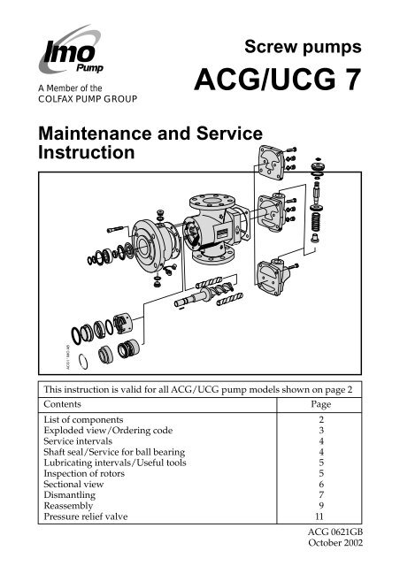
<strong>Screw</strong> <strong>pumps</strong>A Member of theCOLFAX PUMP GROUPACG/UCG 7Maintenance and ServiceInstructionACG1 ' IMO ABThis instruction is valid for all ACG/UCG pump models shown on page 2ContentsPageList of components 2Exploded view/Ordering code 3Service intervals 4Shaft seal/Service for ball bearing 4Lubricating intervals/Useful tools 5Inspection of rotors 5Sectional view 6Dismantling 7Reassembly 9Pressure relief valve 11ACG 0621GBOctober 2002
!Before commencing any work, read this instruction carefully! Failure to complywith these instructions may cause damage and personal injury!For more information about the <strong>pumps</strong> identification code, technical data and performance we refer to theACG/UCG Product description. Fore more information about the <strong>pumps</strong> installation, Start-up and troubleshooting we refer to the IMO Installation and Start-up instruction for low pressure <strong>pumps</strong>.List of componentsValid for all <strong>pumps</strong> in sizes: ACG/UCG 045/052/060/070; Rotor diameter and generation: K7/N7With version codes: N T B E Also valid for pump options: A101, A327, A385V F P Example of pump designationsG std: ACG 045N7 NVBP; option ACG 070N7 NVBP A101QtyComponents included in Spare parts sets:PosNo Denomination G011 G012 G050 G053 G054 G057 G070 Note1010 Power rotor CCW-rot. 1 x (x)1020 Power rotor CW-rot. 1 x x106 Balancing piston 1 x x x 5113 Shaft key 1 x x x120 Distance sleeve 1122 Ball bearing 1 x x124 Retaining ring 1 x x x124A Support ring 1 x x x201 Idler rotor CCW-rot. 2 x (x)202 Idler rotor CW-rot. 2 x x359 Distance washer 1359A Support ring 1 x x x401 Pump body 1424 Sleeve 1 4424A Washer 1 4429 Spindle 1 4437 O-ring 1 4440 Return valve 1451 <strong>Screw</strong> 4/6453 <strong>Screw</strong> 4462 Plug 2 1462A Sealing washer 2 x x x 1473 Grease nipple 1473A Grease nipple cover 1480 Valve housing 1 25010 Front cover 1502 Tension pin 1 6502A Plug 1 6506 Gasket 1 x x x509 Shaft seal 1 x x x514 Retaining ring 1 x x x537 Plug 2537A Sealing washer 2 x x x551 Rear cover 1 3556 Gasket 1 x x x601 Valve cover 1 x 2,7602 Sealing washer 1 x x x x 2605 O-ring 1 x x x x 2608 Valve spindle 1 x 2,7608A Retaining ring 1 x x x x 2612 Set screw 1 x 2,7614 Valve piston 1 x 2,7615 Valve spring 1 x 2Explanations:G011: Rotor setCCW-rotation optionG012: Rotor setCW-rotation (std)G050: Shaft sealG053: Minor kit(G050 + G057) + 122G054: Major kit consistingof: G053+G012 (G011)G057: Joint kitG070: Valve elementACG Pump with DINflangesUCG Pump with ANSIflangesA101: CCWA327: With TuningA385: CCW and TuningNotes:1) Excluded in xxxG2) Excluded in xxxE3) Valid for xxxE4) Valid for pump optionA3275) Included in item 1020or 10106) Included in item 50107) Only sold as G070ACG2 ' IMO ABIMO ABName plate of the pump2 IMO AB, Telephone: + 46 8 50 622 800, Telefax: + 46 8 645 15 09ACG 0621GBE-mail: info@imo.seOctober 2002
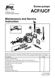
Exploded viewACG/UCG xxBE/BP/BGxxxE551 453462462A608A4626014515010537537A506401556 480453462462A602605608612615462124A124122 120xxxP614514359202453480359A537473473AxxxGVersion xTxx537A5091131020 202CW rotation201ACG3 © IMO ABVersion xVxxDetails in pump option A327See the sectional view p. 61131010CCW rotation (non-standard)Fig. 1Ordering codePos Spare parts sets Part numbers, sizesNo 045 052 060 070Rotor set CW-rotation (std):G012 Normal lead - pump version N7 178913 179507 179515 179523" Low lead - pump version K7 187542 187559 187567 187575Rotor set CCW-rotation (non-std):G011 Normal lead - version N7 186478 186486 186494 186502Low lead - version K7 189641 189642 189643 189644G050 Complete shaft seal - version code xVxx 190335 190336 190338 190340” ” - version code xTxx 174094 174102 174110 174128G053 Minor kit - version code xVxx 191241 191243 191245 191247” ” - version code xTxx 191242 191244 191246 191248G054 Major kit=G012(G011)+G053 - - - -G057 Joint kit 191237 191238 191239 191240G070 Valve element - version code xxxP/G 191250 191250 191251 191251122 Ballbearing 078576 077461 191181 191182Fig. 2Recommendation:For maintenance thefollowing spare partsets are recommended:Set: To be used:G057 Joint kitFor dismantling ofthe pumpG053 Minor kitFor serviceG054 Major kitFor repair afterdamage or greaterwear.Ordering example:For IMO-pump ACG 045N7NVBP, serial number 456789Shaft sealpos G050 p/n 190335Ballbearingpos 122 p/n 078576ACG 0621GBOctober 2002IMO AB, Telephone: + 46 8 50 622 800, Telefax: + 46 8 645 15 09E-mail: info@imo.se3
Service intervalsThe intervals for inspection and replacement of wearparts vary greatly with the properties of the pumpedliquid and can only be determined by experience.All internal parts of the ACG-pump are lubricatedby the pumped liquid. Pumping liquid whichcontains abrasive materials, or liquid that is corrosive,will significantly reduce service lifeand call for shorter service intervals.Wear in the pump may be indicated by:• Vibration• Noise• Loss of capacity• Reduction in flow/pressure• LeakageIn installations where unplanned shut downs mustbe avoided, it is advisable to have a complete pumpavailable for replacement, should any malfunctionoccur. Furthermore we recommend planned inspectionand overhaul at regular intervals, not exceeding3 years.It is recommended always to have the spares includedin minor spare part kit available.!All work carried out on the pump has to beperformed in such a manner that risks forpersonal injury are observed!Inspection of shaft sealAs the seal faces of a mechanical shaft seal arelubricated by the fluid a certain leakage will alwaysbe present. Ten drops per hour can be considered asacceptable.An external visual inspection of the pump is advisableat least every two days to assure that the shaftseal is not leaking too much.Excessively leaking shaft seals should be changedwithout delay, as the leakage normally will growworse and cause additional damage.Follow the instructions in the dismantling/reassemblysession.When working with a shaft seal, cleanliness is ofutmost importance. Avoid touching the seal faces. Ifnecessary, the seal faces should be cleaned immediatelyprior to assembly, using a dustfree cloth andclean solvent.Never use grease on the seal faces.!!Connecting and disconnecting of electriccables must be done only by personnelauthorized to do such work.If the <strong>pumps</strong> operating temperature exceeds60°C let the pump cool off before anyservice, maintenance or dismantling work iscommenced to avoid burn injury.Shaft seal-assembly drawingShaft seal G050 (pos 509)Version code xTxxATTENTIONBe careful to mountthese parts in rightorder and in rightdirection.Version code xVxxACG8 ' IMO ABS2 S1 S4 S6 S9 S7 S5S1 SeatS2 O-ringS4 Seal ringS5 Seal ring carrierS6 O-ringS7 SpringS9 Stop washerS1 SeatS2 O-ringS5 Bellows unitFig. 3Service for ball bearingThe ACG-pump is fitted with an external greaselubricated ball bearing.When delivered from IMO AB, the ball bearings inpump version xVxx are filled with grease of type B.For version xTxx, type C is used.Whenever the ball bearing is removed, it is recommendedto exchange it for a new one.Fit the new ball bearing properly greased andregrease it after one hour of running, while thepump is operating.S2 S1 S5Use an appropriate type of grease, as per table and agrease gun suitable for grease nipple (pos 473)according to DIN 71 412 (ISO 6392).On vertical mounted units the greasing intervals arereduced to half.Installed in dusty or dirty premises or in a corrosiveenvironment it should be lubricated at more frequentintervals.If using others than these recommended greasescheck if it is possible to mix them with each other,otherwise clean before using a new grease.4 IMO AB, Telephone: + 46 8 50 622 800, Telefax: + 46 8 645 15 09ACG 0621GBE-mail: info@imo.seOctober 2002
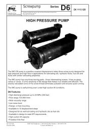
Lubricating intervals in working hoursTemp Pump sizes 045 and 052 Pump sizes 060 and 070max Grease Speed, r/min Speed, r/min°C type 3500* 2900 1750 1450 1150 950 3500* 2900 1750 1450 1150 95070 A 8500 10000 10000 10000 10000 10000 7500 8500 10000 10000 10000 1000090 A 3350 3950 5350 5950 6350 7500 2950 3350 4750 5150 5950 6750110 B 2650 3150 4250 4700 5000 5950 2350 2650 3750 4100 4700 5350130 B 1050 1250 1650 1850 2000 2350 900 1050 1500 1600 1850 2100155 C 650 750 1050 1150 1250 1500 600 650 950 1000 1150 1300*) at rotation speed > 3 500 r/min special instructions are given by IMO AB.Recommended greases (the availability of the greases can differ locally):Type A: BP Energrease LS 3, Esso Beacon 2, Mobilgrease HP 222, Shell Alvania G3, Texaco Multifak EP2, SKF LGMT2,Q8 REMBRANDT EP2, CASTROL APS2, ELF ROLEXA 3, TOTAL MULTIS TIR EP3, FINA MARSON L3.Type B: BP Energrease LC2, CHEVRON SRI GREASE 2, Esso Unirex N3, Mobilith SHC220, SHELL RETINAX LX,SHELL Albida LX, VAL-PLEX EP GREASE, Texaco Hytex EP2, SKF LGHQ 3, Q8 RUBENS, CASTROL LMX,INDUSTRIAL GREASE HEAVY, TOTAL MULTIS THT2, FINA PLUTON L2.Type C: Mobilith SHC 460Pump size 045 052 060 070Grease amount (g) 4 6 7 9!When handling liquids which may involvefire hazards appropriate precautions toavoid danger are to be taken.!Before any maintenance work, ensurethat the driver is deenergized and thepump hydraulically isolated.!In case of failure for a system with elevatedpressure, fluid jets may cause injury and/ordamage.Useful toolsACG7 © IMO ABPullerSlide calliperdAllenkeysLDMountingsleeve2 pcs ofscrewdriverMounting kit (M8)PlasticmalletFineemeryPair ofpliersOil can GreaseMounting sleeve dimensionsPump size D d L Part NoACG/UCG 045 ø 25.0 ø 21.0 100 188887ACG/UCG 052 ø 31.0 ø 26.0 100 188888ACG/UCG 060 ø 35.0 ø 31.0 100 188889ACG/UCG 070 ø 42.0 ø 36.0 100 188890dLGREASEMounting sleeveDInspection of rotorsIf an indication of a worn pump is noticed (see serviceintervals above), a brief inspection of the idler rotorsis recommended.A quick inspection of the idler rotors can be madesimply by removing the rear cover or valve cover.Note that the driver must be deenergized and thepump hydraulically isolated before the rear cover isremoved. Provisions to handle the fluid are to bemade. If a more thorough investigation is needed,proceed as under ”Dismantling”.Internal clearances in the pump, which are vital for itsproper function, may have been affected by wear.Acceptable wear can be determined only by experienceof the actual application. As a rule of thumb thefollowing max clearance values may apply:• Between rotor and bores or bushings: 0.2 mm• Between rotor flanks: 0.4 mmFor light duties (low pressure, medium viscosity)even bigger clearances may be acceptable but for lowvisc./high pressure duties the limit will be lower.Also check if there are major scratches on these parts.!!When handling liquids that may harmskin use gloves and/or protective clothing.Oil leakage may make the floor slipperyand cause personal injury.Fig. 4ACG 0621GBOctober 2002IMO AB, Telephone: + 46 8 50 622 800, Telefax: + 46 8 645 15 09E-mail: info@imo.se5
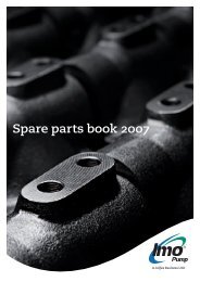
Sectional viewVersion xxBP424A424437429Option A327Version xxxEVersion xxxGFig. 56 IMO AB, Telephone: + 46 8 50 622 800, Telefax: + 46 8 645 15 09ACG 0621GBE-mail: info@imo.seOctober 2002
DismantlingA. B.• Turn theelectricity OFF.Fig. 6• Close the valves.• Remove the pumpfrom the system.ATTENTIONUse appropriate vessels to collect oil spillagewhen removing and opening the pump.ACG9 © IMO ABACG10 © IMO AB• Note the axial position of the shaft coupling.• Release the stop screw.Fig. 7C. D.113• Remove the shaftcoupling.• Remove the key113.ACG14 ' IMO ABACG11 ' IMO ABACG12 ' IMO ABFig. 8 Fig. 9E.F.124451124A514ACG13 ' IMO AB• Remove the screws 451.• Remove the retaining rings 124 and 514.• Remove the support ring 124A.Fig. 10ACG 0621GBOctober 2002Fig. 11IMO AB, Telephone: + 46 8 50 622 800, Telefax: + 46 8 645 15 09E-mail: info@imo.se7
G. H.122120359359AFig. 12• Remove thefront cover5010 with apuller.I.5010ACG15 © IMO AB5010ACG16 ' IMO AB• Push out the ballbearing 122 togetherwith the distancesleeve 120. If there istight fit use a mountingsleeve and amallet.• Remove the distancewasher 359 and theMounting support ring 359A.sleeveS1Fig. 13ACG17 © IMO ABS25065010!No toolsfrom thissideThe sealingsurfaces of theshaft seatshould not betouched withthe fingers.J –xVxx.Shaft sealVersion xVxxS5S5• Turn the front cover 5010 upside down.• Push out the seat from the front cover 5010.• Remove the o-ring S2.• Remove the gasket 506.Fig. 14J–xTxx.Shaft sealVersion xTxxO ABS4S6S5• Unscrew theseal ringcarrier S5screws andtake off theseal ringcarrier S5together withthe seal ring S4and the o-ringS6.Fig. 15K.ACG20 © IMO ABACG18 © IMO AB• Pull the power rotor 1020 out of the pumpbody and place it into the jaws of a jaw vicewith soft jaws or a column drilling machine.• Push with two drivers as shown on thesketch, to remove the shaft seal.2021020• Take out theidler rotors.• Clean all partsthat are goingto be usedagain.Fig. 16Fig. 178 IMO AB, Telephone: + 46 8 50 622 800, Telefax: + 46 8 645 15 09ACG 0621GBE-mail: info@imo.seOctober 2002
ReassemblyA.ACG21 © IMO ABFig. 18S4S5BalancepistonACG23 © IMO AB202B–xTxx.Version xTxxS6• Lubricate theidler rotors andfit them into thepump.Lubricationgroove turneddownwards.• Open a packagewith a new shaftseal 509 versionxTxx.• Place the seal ringcarrier S5 on theshaft of the powerrotor 1020 flushagainst the balancepiston andlock it with itsstop screws. Fitthe o-ring S6 andthe seal ring S4.ACG22 ' IMO ABB–xVxx.Version xVxxFig. 191020C.ACG24 © IMO ABS1S2S55010• Carefully place thepower rotor 1020into the jaw vicewith soft jaws.• Lubricate allsurfaces of thepower rotor 1020.• Open a packagewith a new sealing509, version xVxx.• Place the bellowsunit S5 on the shaftof the power rotorand press it downagainst the balancepiston (106) (Seefig. 5).• Lubricate the O-ring S2 and therecess of the frontcover 5010.• Clean the sealingfaces and fit theseat S1 into thefront cover 5010.Mind the positionof the retainingpin if applicable.Fig. 20Fig. 21D.120122Grease• Lubricate the balance piston 106 with a thick oil (ISO VG 460).• Fit the front cover onto the power rotor 1020 untill it rests onthe bellows unit S5.1020359359AMounting kit5010• Fit the support ring 359A and the distance washer 359 into thefront cover. Mind the position of the distance washer 359.• Fit the distance sleeve 120 into the front cover 5010.• Fill the ball bearing with appropriate grease. See page 5 forgrease selection.• Fit the ball bearing 122 onto the shaft.106ATTENTIONThe open side of the bearing towards the cover.• Fit the mounting sleeve and push the bearing toits final position in the front cover. To do thissome force is required. Use Your column drillingmachine or mounting kit (see fig 4).!Do not use a hammer etc. as this mightdamage the shaft seal and ball bearing.Fig. 22ACG 0621GBOctober 2002IMO AB, Telephone: + 46 8 50 622 800, Telefax: + 46 8 645 15 09E-mail: info@imo.se9
E.124124A• Fit the support ring 124A and the retainingring 124 on the shaft.• Fit the retaining ring 514 back in place.51426 ' IMO ABFig. 23F.• Fit the key back in position, see fig. 9.• Fit the shaft coupling back into place (see fig. 7and 8) with the same methode used whenfitting the ball bearing.Fig. 24!Do not use a hammer etc. as this mightdamage the shaft seal and ball bearing.G.537A53750101020• Remove the plug 537 and washer 537A.• Hold the rotor unit horizontally with thebore for 537 upwards. Carefully fill thespace completely with thin oil(f. ex. ISO VG 46).• When the oil is flooding, reassemble theabove parts in reverse order.• Slowly turn the shaft a few turns to makesure it moves freely (a certain resistancefrom the shaft seal is normal but it must bethe same during the turns).Fig. 2510 IMO AB, Telephone: + 46 8 50 622 800, Telefax: + 46 8 645 15 09ACG 0621GBE-mail: info@imo.seOctober 2002
H.4515010• Place the gasket 506 on the pump body 401.• Lubricate the power rotor 1020 and fit thefront cover 5010 together with the rotor setinto the pump body. Mind the position ofthe tension pin 545.• Fit the screws 451 and tighten them crosswise.1020506ACG29 ' IMO AB401Fig. 26Fig. 27I.• Put the pump back into the system andproceed according to instructions under”Start-up” in the installation manual.Pressure relief valveReplacement of O-ring 605• To avoid changing the setting of the valve, use anAllen key to prevent spindle 608 to turn.Unscrew cover 601 and pull up unit 601/608.• Remove retaining ring 608A and pull the spindle608 out of cover 601. Replace O-ring 605 andassemble the unit 601/608 in reverse order.Replace retaining ring 608A if necessary andwasher 602.• Fit the unit 601/608 in the valve. Make sure the608 enters the set screw 612 and use the Allenkey to prevent 608 to turn when cover 601 istightened.Replacement of Valve Element G070• Release the spring tension by turning the spindle608 CCW with an Allen key. Use the Allen key toprevent spindle 608 to turn and unscrew cover601 but do not remove it yet.• Remove the set screw 612 by turning the spindle608 CCW. Pull out the valve piston/spring unit614/615.• Fit the valve element in reverse order with a newwasher 602. Turn the spindle 608 CW until theset screw leave enough room for cover 601. Usethe Allen key to prevent 608 to turn further whencover 601 is tightened.• Adjust the valve setting according to the "Installationand Start-up Instruction for IMO Lowpressure <strong>pumps</strong>".ACG 0621GBOctober 2002Fig. 28Version PVersion GIMO AB, Telephone: + 46 8 50 622 800, Telefax: + 46 8 645 15 09E-mail: info@imo.seACG30 ' IMO AB480453462462A462453480608A60160260560861261561411
www.imo.seIMO AB:P. O. Box 42090, SE 126 14 Stockholm, SwedenTelephone: +46 8 50 622 800, Telefax: +46 8 645 1509