Catalog Nex 17.5kV metalclad-cubicle - Schneider Electric
Catalog Nex 17.5kV metalclad-cubicle - Schneider Electric
Catalog Nex 17.5kV metalclad-cubicle - Schneider Electric

Create successful ePaper yourself
Turn your PDF publications into a flip-book with our unique Google optimized e-Paper software.
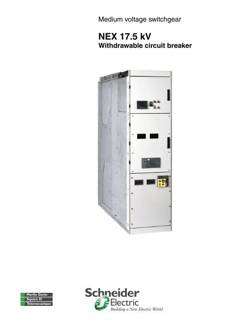
Medium voltage switchgearNEX 17.5 kVWithdrawable circuit breaker
NEX range1 to 17.5 kVContentsPresentation 2NEX: versatile 2NEX: <strong>Schneider</strong> <strong>Electric</strong> licenced product design 3NEX: <strong>Schneider</strong> <strong>Electric</strong> products inside 4NEX 17.5 range 9Description 9Protection of people 13General characteristics 14Cubicle description 15IF Incomer and Feeder 15BC Bus Coupler 16RF Bus Riser 17VT Busbar Voltage Transformer 18Installation 19Connections 19Implementation example 201
PresentationNEX: versatilePE56220For over 45 years, <strong>Schneider</strong> <strong>Electric</strong> has provided medium voltage electricalnetwork protection, monitoring and control solutions in the public distribution,industry and building sectors.NEX units 12 kV/17.5 kV switchboardNEX is indoor, metal-enclosed switchgear designed for the MV section of HV/MVand MV/MV substations.NEX is a medium voltage equipment comprising <strong>cubicle</strong>s with breaking devices,sensors, medium voltage connections and auxiliaries.For all your applications:b industrial process substations,b infrastructure supply substations.PE56221NEX offers you:b flexible and adapted solutions,b the experience of a major electrical manufacturer,b dedicated engineering.PE56223PE56222The switching devices are of the vacuum withdrawable type.NEX design takes into account three categories of users requirements:b reliabilityv type testing was carried out for each performance level in the NEX range,v maintenance limited to simple, routine operating checks and cleaning,and greasing every 5 to 10 years.b simplicityv a user interface which is easily understood by everybody,v interlocks and padlocks preventing operator errors,v easy installation due to identical civil engineering dimensions for all <strong>cubicle</strong>s.b safety of operation personnelv operations are all performed from the front, including access to connectionsand busbars,v racking in and out is only possible with the door closed,v internal arc withstand developed for all functional units,v one single ‘‘anti-reflex” handle is used for all NEX operations.2
PresentationNEX: <strong>Schneider</strong> <strong>Electric</strong> licencedproduct designPE56224<strong>Schneider</strong> <strong>Electric</strong> designNEX design has been achieved thanks to full up to date means such as computeraided design software, synthetic laboratories, simulation of behaviour...NEX is designed according to the best practices in terms of installation, operationand maintenance:b reliability: the user benefits from the progress provided by expertise developedby <strong>Schneider</strong> <strong>Electric</strong> in the area of operating dependability for more than 45 years,b simplicity: little effort is required for local manual operations, icon-illustratedinstructions on each front panel make the operating sequence and switching devicestatus very simple to understand,b safety: very comprehensive set of mechanical and electrical interlocks preventsoperator errors.MT20066CertificationThe type certificate of conformity guarantees that the product:b has been subjected to type testing according to standardised procedures(ISO/IEC 17025) in approved laboratories by independent organisations,b is in conformity with recognised international standards.For NEX, certification has been carried out by EN 45011 approved externalorganisations, members of the STL (Short-circuit Testing Liaison).PE40039Conformity with standardsAll the different <strong>cubicle</strong>s have been tested in accordance to the latestIEC publication:b 62271-200 (previously 60298) and 60694 relating to construction of mediumvoltage switchgear and controlgear assemblies,b 62271-100 (previously 60056) relating to construction of medium voltagecircuit breakers,b 62271-102 high voltage alternating current disconnectors and earthing switches.3
PresentationNEX: <strong>Schneider</strong> <strong>Electric</strong>products insideThe reliability and dependability ofa <strong>cubicle</strong> is also assumed by the internalcomponents, producing between thema coherent architecture.This technology provides users withthe best guarantee of continuity of servicefor their installations.Evolis vacuum circuit breakers from 1 to 17.5 kVEvolis circuit breaker is used to protect and control MV public or industrialdistribution network.b Rated voltage 12 kV and 17.5 kV.b Short circuit breaking capacity up to 31.5 kA.b Rated normal current from 630 A to 2500 A.b Axial magnetic field (AMF) breaking technology.b Withdrawable version.The Evolis circuit breaker equips <strong>cubicle</strong>s IF and BC at ratings of up to 17.5 kV.PE55101High electrical enduranceA magnetic field is applied in the axis of the vacuum interrupter contacts.This process maintains the arc in diffused mode even at high current values.It ensures optimal dispersion of the energy over the contact surface and avoidslocalised temperature rise.The advantages of this technique are:b a very compact vacuum interrupter,b low energy dissipation of the arc in the vacuum interrupters.Evolis is in conformity with the highest electrical endurance class(IEC 62271-100: class E2).MT20106High mechanical enduranceThe magnetic field is generated by a patented outside coil which surroundsthe contact area. This solution has many advantages:b a simplified and therefore reliable vacuum interrupter unit,b heavy duty contacts which do not distort under repeated switching operations.This is the first time that a low voltage device control mechanism has been usedon a medium voltage circuit breaker. The Masterpact control unit used on Evolishas the advantages of a system which has been proven for over 10 yearsin hundreds of thousands of installations.Evolis is in conformity with the most demanding mechanical endurance class(IEC 62271-100: class M2).MT20109Operating mechanism descriptionEvolis range circuit breakers are actuated by a Masterpact type operatingmechanism, that ensures a switching device closing and opening ratethat is independent of the operator.This operating mechanism, which is always motorised, can perform remote controlfunctions and enables fast reclosing cycles.This operating mechanism includes mechanical devices:b an energy storage mechanism stores the energy required in the springs,to close and then to open the device,b a manual lever-controlled arming device,b an electric motor-controlled (MCH) arming device which automatically rearmsthe control unit as soon as the device is closed (re-arming time less than 4 s),b a mechanical opening and closing device using two push buttons situatedon the front circuit breaker panel which are accessible with the <strong>cubicle</strong> door open(circuit breaker in the test position).For the door closed control unit (circuit breaker racked in): the circuit breaker canbe opened by controlling the propulsor unit.4
PresentationNEX: <strong>Schneider</strong> <strong>Electric</strong>products inside (cont.)Each NEX functional unit can be equippedwith a comprehensive protection,monitoring and control system comprising:b instrument transformers to measure thenecessary electrical values (phase current,residual current, voltages, etc.),b protection relays, providing functionsadapted to the part of the network to beprotected,b metering equipment, to inform operators,b low voltage relaying, i.e. to providecontrol of the breaking device andof the withdrawable part,b various auxiliaries: secondary circuit testunits, etc.DE56602PE55170Sepam: protection, monitoring and control unitsSepam, is a range of digital monitoring protection and control units.Sepam is at the centre of the protection, monitoring and control system for NEXfunctional units: all the necessary protection, metering, control, monitoring andsignalling functions are carried out by Sepam.Like the NEX range, the Sepam range is a range of units defined to providean optimal solution for each application, and includes (eg):b Sepam S, substation incomer and feeder,b Sepam B, bussectioning,b Sepam T, transformer feeder,b Sepam G, generator feeder.Sepam advantagesReliabilityb Over 20 years of experience in multi-function digitalprotection relays.b Over 150,000 Sepam units in service in more than90 countries.Qualityb Quality design based on dependability studiesand strict definition of environmental constraints:temperature, pollution, EMC, dielectric strength…b Quality manufacturing based on procurementagreements with suppliers and inspection throughoutall manufacturing phases.Simplicity of useb Ergonomic and intuitive user machine interface(UMI).b User friendly and powerful PC setting software.Protection chainThe Sepam protection units combined with innovative current sensors providea comprehensive measurement, protection and energy management chain.A high performance, economical solutionThe modular Sepam offer provides a cost effective solution tailored to everyrequirement.Easy to order and installAll the components in the protection chain are referenced and can be deliveredvery quickly.The power of a multi-functional digital unitSepam is more than a simple protection relay, it is truly multi-functional unit notablyoffering:b circuit breaker diagnosis functions (switching counter and time, rearming time,cumulated broken A 2 ),b direct circuit breaker control whatever type of release unit,b remote equipment operation using the modbus communication option.The Sepam will operate with Low Power Current Transducers (LPCT) as definedby standard IEC 60044-8.5
PresentationNEX: <strong>Schneider</strong> <strong>Electric</strong>products inside (cont.)Sepam series 20, series 40, selection guideSepam Protections ApplicationsBasic Specific Substation Transfo Motor Generator BusbarSepam series 20b 10 logic inputsb 8 relay outputsb 8 temperature probe inputsb 1 Modbus communicationportDE51730CurrentprotectionS20 T20 M20DE51731Voltage andfrequencyprotectionLoss of mains(ROCOF)B21B22Sepam series 40b 10 logic inputsb 8 relay outputsb 16 temperature probe inputsb 1 Modbus communicationportb logic equations editorDE51732Current,voltage andfrequencyprotectionDirectionalearth faultS40 T40 G40S41M41Directionalearth faultand phaseovercurrentS42T426
PresentationNEX: <strong>Schneider</strong> <strong>Electric</strong>products inside (cont.)Instrument transformersPE56225PE56227Voltage transformerwith fusePE56226Voltage transformerPE56228Voltage transformersb measuring, metering and monitoring devices,b relays or protective devices,b auxiliary LV sources for various types of switchgear.All these devices are protected and insulated from the MV section.They are in conformity with standard IEC 60044-1.<strong>Schneider</strong> <strong>Electric</strong> has drawn up a list of voltage transformers which are appropriatefor use with digital protection devices.They are installed at the bottom of the functional unit. The energized partis entirely encapsulated in an epoxy resin, which provides both electrical insulationand excellent mechanical strength.They include the following models:b with one insulated MV terminal, for connection between neutral and phaseconductors in three-phase systems with withdrawable MV fuses,b with two insulated MV terminals, for connection between phase conductors.Current transformersConventional current transformers are used to provide power to metering,measuring or control devices. They measure the value of primary current from 10 Ato 2500 A. They are in conformity with standard IEC 60044-2.<strong>Schneider</strong> <strong>Electric</strong> has drawn up a list of current transformers which areappropriate for use with digital protection devices in order to make it easierto determine accuracy characteristics.They are installed in the rear part of the functional unit. The energized part isentirely encapsulated in an epoxy resin, which provides both electrical insulationand excellent mechanical strength.DE56603LPCTLV toroidal typeLPCTMV block typeLPCT low power current transducerLPCT’s are specific current sensors with a direct voltage output of the “Low PowerCurrent Transducer” type, in conformity with standard IEC 60044-8.LPCT’s provide metering and protection functions.They are defined by:b the rated primary currentb the extended primary currentb the accuracy limit primary current or the accuracy limit factor.These have a linear response over a large current range and do not start tosaturate until beyond the currents to be broken.DE56604Earthing switchAn earthing switch is used to earth and short-circuit the cable ends before workis performed on the cable connection compartment.In a VT functionnal unit, the earthing switch is used to earth the busbar of theswitchboard. This switch, with a making capacity, complies with IEC 60271-102and comprises:b a fast-acting closing mechanism independent of the operator,b a locking device which stops it from being operated until the circuit breakerhas been opened and withdrawn,b 3 voltage capacitive dividers incorporated into the insulators which support theterminal plates, and connected to the VPIS mounted on the front plate, to indicatewhether the cables are live or not.Voltage Presence Indicator System (VPIS)The VPIS, combined with the capacitive divider insulators of the power circuit unit,provides an indication by lights of the voltage presence on each phase of the maincircuit.The voltage presence indicator unit is installed on the front of the earthing switchoperating mechanism box.The voltage presence indicator unit covers two voltage ranges, in accordancewith standard IEC 61958:b 3.2 to 7.2 kV,b 10 to 24 kV.7
PresentationNEX: <strong>Schneider</strong> <strong>Electric</strong>products inside (cont.)PE56229Power monitoring and control power monitoring deviceThe PowerLogic Power Meter is a cost effective, high performance meter.It can operate as a stand alone device or as part of the power monitoring andcontrol system from <strong>Schneider</strong> <strong>Electric</strong>: the PowerLogic system (contact us formore information).b Essential power monitoring:v revenue-class; accuracy 0.2% current/voltage,v on-board memory for energy consumption analysis,v on-board clock/calendar for time/date stamping.b Application flexibility:v separate meter and display modules,v direct-connect up to 600 V: higher voltages with PTs.Other devices, such as the PowerLogic Circuit Monitor, are available for MV and LVnetworks. Main functions include comprehensive power monitoring, power qualityanalysis and recording and optional input, output control.PE56230PE56231PE56232Low voltage <strong>Schneider</strong> <strong>Electric</strong> componentsIntegration of standardised <strong>Schneider</strong> <strong>Electric</strong> and Telemecanique componentsin the LV compartment.Example:b LV circuit breakers cover all ratings from 1 to 100 A,b push-button,b rotary switch,b light signal,b photoelectric sensors.PE56233Fuses<strong>Schneider</strong> <strong>Electric</strong> fuses provide protection to medium voltage distribution devices(from 3 to 36 kV) from both the dynamic and thermal effects of short-circuit currentsgreater than the fuse’s minimum breaking current.Considering their low cost and their lack of required maintenance, medium voltagefuses are an excellent solution to protect various types of distribution devices:medium voltage current consumers (transformers, motors, capacitors, etc.),public and industrial electrical distribution networks.8
NEX 17.5 rangeDescriptionPE56234BusbarsLV control cabinetSepamLPCTCircuit breakerCurrenttransformersCablesconnectionVoltagetransformersarea (option)9
NEX 17.5 rangeDescription (cont.)Make up of a NEX 17.5 switchboardNEX 17.5 switchboards are made up of several interconnected functional units.Power connections are made between functional units within a switchboard viaa single busbar.The electrical continuity of all metal frames is provided by the connectionof each functional unit’s earthing busbar to the switchboard’s main earthing circuit.Low voltage wiring trays are provided in the switchboard above the LV controlcabinets.LV cables can enter the switchboard through the top or bottom of each functional unit.Description of a functional unitA functional unit comprises all equipment in the main and auxiliary circuitswhich together provide a protection function. Each functional unit combinesall the components which are required to fulfil this function:b the <strong>cubicle</strong>,b the protection, monitoring and control system,b the withdrawable part.The <strong>cubicle</strong>As defined by IEC standard 62271-200, the functional unit is of LSC2B-PM type(low of service continuity category). The medium voltage parts are compartmentedusing metallic partitions (PM class) which are connected to earth and whichseparate:b the busbars,b the withdrawable part (circuit breaker, disconnector truck or earthing truck),b MV connections, earthing switch, current sensors and voltage transformersas required.NEX 17.5 guarantees a high level of protection of people; when a compartmentcontaining a main circuit is open, the other compartments and/or functional unitsmay remain energised.The low voltage auxiliaries and monitoring unit are in a control cabinet separatedfrom the medium voltage section.Four basic <strong>cubicle</strong> layouts are offered:b Incomer or Feeder IFb Bus CouplerBCb Bus RiserRFb Busbar Voltage Transformer VTIF and BC <strong>cubicle</strong>s have withdrawable circuit breaker.The protection, monitoring and control systemThis includes:b voltage transformers,b Sepam, protection, monitoring and control unit,b current sensors, which may be of 3 types:v conventional current transformers,v low voltage toroid type current transformers (max. 1250 A),v LPCT (Low Power Current Transducer) MV block type (max. 1250 A),v LPCT (Low Power Current Transducer) LV toroidal type (max. 1250 A).The withdrawable partThis includes:b the circuit breaker, the earthing truck with its closing and opening mechanism,or the disconnector truck,b the lever-type propulsion mechanism for racking in-out,b interlocks to fix the withdrawable part on the fixed part either in service positionor disconnected.10
NEX 17.5 rangeDescription (cont.)PE56235Technical dataRated voltage (kV)Rated insulation levelPower frequency withstand voltage50 Hz - 1 min (r ms kV)Lightning impulse withstand voltage1.2/50 μs (kV peak)Nominal current and maximum short time withstand currentFunctionnal unit with circuit breaker12 17.528 3875 95Short time withstand current Ith. max (kA/3 s) 25 2531.5 31.5Rated current In max busbars (A) 2500 2500Internal arc withstand (option)In CB (A) 630 6301250 12502500 2500IAC-AFLR (kA/0.5 s) 25 25IAC (internal arc classification):The metal enclosed switchgear mayhave different types of accessibilityon the various sides of its enclosure.For identify purpose of different sides ofthe enclosure, the following code shallbe used (according to IEC 62271-200standard).A: restricted access to authorizedpersonnel onlyF: access to the front sideL: access to the lateral sideR: access to the rear sideLSC2B (lost of service continuity):This category define the possibilityto keep other compartments energisedwhen opening a main circuit compartment.Protection indexb IP3X or IP4X for the enclosure (option),b IP2X between each compartment.Constructionb internal arc withstand (classification IAC): AFLR,b 3 compartments (classification LSC2B-PM according to IEC 62271-200),b all the metal surfaces in the panels are corrosion proof,b panels are produced using hot dipped galvanisation steel sheet in accordanceto ISO 3575 or electro zinc coated steel sheet in accordance to ISO 5002,b busbar: exposed for 12 kV and insulated for 17.5 kV.Connectionsb front and/or rear access,b conductor entry from below.11
NEX 17.5 rangeDescription (cont.)PE56238 PE56237PE56236Operating conditionsNormal operating conditions, according to IEC 60694 for indoor switchgearb ambient air temperature:v less than or equal to 40°C,v less than or equal to 35°C on average over 24 hours,v greater than or equal to – 5°C.b altitude:v less than or equal to 1000 m,v above 1000 m, a derating coefficient is applied (please consult us).b atmosphere:v no dust, smoke or corrosive or inflammable gas and vapor, or salt(clean industrial air).b humidity:v average relative humidity over a 24 hour period y 95%,v average relative humidity over a 1 month period y 90%,v average vapor pressure over a 24 hour period y 2.2 kPa,v average vapor pressure over a 1 month period y 1.8 kPa.Storage conditionsIn order to retain all of the functional unit’s qualities when stored for prolongedperiods, we recommend that the equipment is stored in its original packaging,in dry conditions sheltered from the sun and rain at a temperature of between– 25°C and + 55°C.StandardsThe NEX17 range meets the following international standards:b IEC 62271-1: clauses common to high voltage switchgear,b IEC 62271-200: metal-enclosed switchgear for alternating currentat rated voltages of between 1 and 52 kV,b IEC 62271-100: high voltage alternating current circuit breakers,b IEC 60282-2: high voltage fuses,b IEC 62271-102: alternating current disconnectors and earthing switchesb IEC 60529: defining the protection indices provided by enclosures.12
NEX 17.5 rangeProtection of peopleDE56605Withdrawable unit and earthingComposed of:b withdrawable circuit breaker,b complete cradle equipped with metallic safety shutters and dedicated bushings,b earthing switch with making capacity,b LV connector between LV control cabinet and CB auxiliaries.DE56606InterlockingThe <strong>cubicle</strong> integrates the different interlocking to prevent incorrect operationby the operator.NEX secures operation to:b access the cable compartment,b rack in and out,b operate the earthing switch,b open the CB door.DE56607Safetyb General structure that allows gas evacuation pressure reliefs device.b Each compartment is designed with a specific chimney for upward gasevacuation.13
NEX 17.5 rangeGeneral characteristicsPresentationThe NEX range comprises 4 functional applications.The table below can be used to link requirements to functional unitsand gives basic information on the general composition of each unit.DE56611Single line diagram Designation Function See details pageIFIncomer and FeederConnection to incomeror feeder lines14DE56612BCBus CouplerCoupling of two busbarssystems15DE56613RFBus Riser - Fixed typeSolid busbar link to be usedin association with a BC unit16DE56615VTBusbar Voltage TransformerConnection VT to the busbarfor metering1714
Cubicle descriptionIFIncomer and FeederDE56616Rated voltage(kV)Rated insulation levelPower frequency withstand voltage50 Hz - 1 min ( rms kV)Lightning impulse withstand voltage1.2/50 μs (kV peak)12 17.528 3875 95Rated current (A) 630 b b bBreaking capacity (kA) 25 b bShort timewithstand currentDimensions1250 b b b2500 b b31.5 b b b b b b(kA/3 s) 25 b b(mm)31.5 b b b b b bWidth (W) 650 650 800 800 900 800 800 900Height (H) 2320Depth (D) top entry basic 2195bottom entry basic 1595internal arc 1780DE56617Functionsb Low voltage cabinetv standard heightv local designb Circuit breakerv Evolis range - vacuum technologyb Voltage transformersv with withdrawable fusesv fixed with fusesv fixed without fusesb Earthing switchb Voltage indication (VPIS)b MV cables connectionv bottom entryv top entryb Current transformersv 3 MV typev 6 MV typev 3 MV low powered CTs (up to 1250 A)v LV torroidal CTs on MV primary bar (up to 1250 A)b Surge arrestersb Anticondensation heaters15
Cubicle descriptionBCBus CouplerDE56618Rated voltage(kV)Rated insulation levelPower frequency withstand voltage50 Hz - 1 min ( rms kV)Lightning impulse withstand voltage1.2/50 μs (kV peak)12 17.528 3875 95Rated current (A) 1250 b b bBreaking capacity (kA) 25 bShort timewithstand currentDimensions(kA/3 s) 25 b(mm)2500 b b31.5 b b b b31.5 b b b bWidth (W) 650 800 900 800 900Height (H) 2320Depth (D) basic 1595internal arc 1780DE56619Functionsb Low voltage cabinetv standard heightv local design, special adaptationb Circuit breakerv Evolis rangeb Voltage transformersv withdrawable fusedv fixed fusedv fixed unfusedb Earthing switchb Voltage indication (VPIS)b Current transformersv 3 MV typev 6 MV typev 3 MV low powered CTs (up to 1250 A)v LV torroidal CTs on MV primary bar (up to 1250 A)b Surge arrestersb Anticondensation heaters16
Cubicle descriptionRFBus RiserDE56620Rated voltage(kV)Rated insulation levelPower frequency withstand voltage50 Hz - 1 min ( rms kV)Lightning impulse withstand voltage1.2/50 μs (kV peak)12 17.528 3875 95Rated current (A) 1250 b b bShort timewithstand currentDimensions(kA/3 s) 25 b(mm)2500 b b31.5 b b b bWidth (W) 650 800 900 800 900Height (H) 2320Depth (D) basic 1595internal arc 1780DE56621Functionsb Low voltage cabinetv standard heightv local design, special adaptationb Voltage transformersv withdrawable fusedv fixed fusedv fixed unfusedb Anticondensation heaters17
Cubicle descriptionVTBusbar Voltage TransformerDE56622Rated voltage(kV)Rated insulation levelPower frequency withstand voltage50 Hz - 1 min ( rms kV)Lightning impulse withstand voltage1.2/50 μs (kV peak)Short timewithstand currentDimensions(kA/3 s) 25 b(mm)12 17.528 3875 9531.5 b bWidth (W) 650 800 800Height (H) 2320Depth (D) basic 1595internal arc 1780DE56623Functionsb Low voltage cabinetv standard heightv local design, special adaptationb Voltage transformersv withdrawable fusedv fixed fusedv fixed unfusedb Earthing switchb Voltage indication (VPIS)b Surge arrestersb Anticondensation heaters18
InstallationConnectionsPE56239Switchgear resistance to ageing in a substation depends on3 key factorsb The need for correctly made connectionsNew cold connecting technologies offer easy installation and favour durabilityin time. Their design means they can be used in polluted environments with harshatmospheres.b The impact of relative humidityThe installing of a heating element is essential in climates with high relativehumidities and significant temperature differentials.b Ventilation controlThe dimensions of air vents must be appropriate for the dissipated energyin the substation. They must only sweep across the transformer environment.Cold connected terminals<strong>Schneider</strong> <strong>Electric</strong>’s experience has led it to favour this technology whereverpossible for optimum durability.The maximum acceptable cable cross-section for standard assemblies are:b 630 mm 2 for incomer or feeder <strong>cubicle</strong>s with single-pole cables;b 400 mm 2 for incomer or feeder <strong>cubicle</strong>s with three-pole cables;b 95 mm 2 for transformer protection <strong>cubicle</strong>s with fuses.Access to the compartment is only possible when the earthing switch is closed.Tightening torques for cables will be attained using a dynamo wrench set to 50 mN.DE56624Dry, single core cableShort end piece, cold connectablePerformance3 to 17.5 kV - 400 A - 2500 ACross section mm 2 50 to 630 mm 2SupplierNumber of cablesCommentsall suppliers of cold connectable terminals:Silec, 3M, Pirelli, Raychem...1 to 6 per phasefor greater cross section and number of cables,please consult usDry, three core cableShort end piece, cold connectablePerformance3 to 17.5 kV - 400 A - 2500 ACross section mm 2 50 to 240 mm 2SupplierNumber of cablesCommentsall suppliers of cold connectable terminals:Silec, 3M, Pirelli, Raychem...1 to 2 per phasefor greater cross section and number of cables,please consult us19
InstallationImplementation exampleLine up switchboardDE566006006006502 feeders <strong>cubicle</strong>IF650 900 900 900Incomer <strong>cubicle</strong>IFBus couplerBCBus riserRF900 650 650 650 600Incomer <strong>cubicle</strong>IF3 feeders <strong>cubicle</strong>IF1200Civil engineering with utility space(*) Minimum dimensionsAccess to the premisesDE56601600 *2500 *3600 *1650 *20 times cable diameter *Space for MV cablesSpace for LV cables (if required)Note: for further information, refer to the civil engineering guide,user and instruction manual.20
<strong>Schneider</strong> <strong>Electric</strong> Industries SASAs standards, specifications and designs develop from time to time, always askfor confirmation of the information given in this publication.This document has beenprinted on ecological paperPublishing: <strong>Schneider</strong> <strong>Electric</strong>Design: GraphèmePrinting: Imprimerie du Pont de Claix/JPFAMTED302016EN © 2007 - <strong>Schneider</strong> <strong>Electric</strong> - All rights reservedART.41184 09-2007