

LCD Module User Manual
LCD Module User Manual
LCD Module User Manual

Create successful ePaper yourself
Turn your PDF publications into a flip-book with our unique Google optimized e-Paper software.
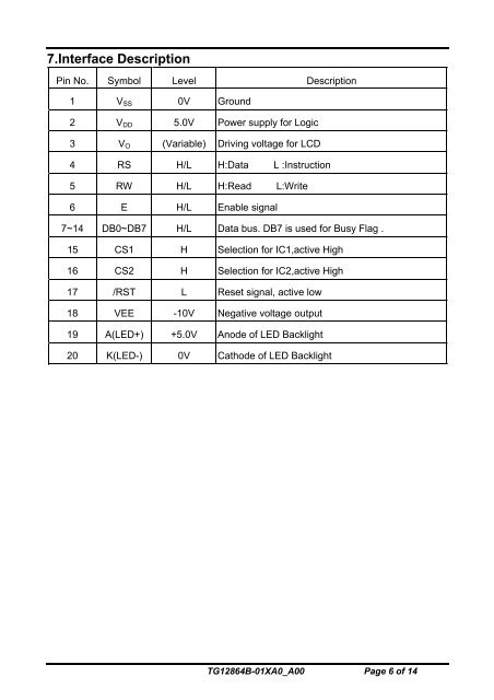
7.Interface DescriptionPin No. Symbol Level Description1 V SS 0V Ground2 V DD 5.0V Power supply for Logic3 V O (Variable) Driving voltage for <strong>LCD</strong>4 RS H/L H:Data L :Instruction5 RW H/L H:Read L:Write6 E H/L Enable signal7~14 DB0~DB7 H/L Data bus. DB7 is used for Busy Flag .15 CS1 H Selection for IC1,active High16 CS2 H Selection for IC2,active High17 /RST L Reset signal, active low18 VEE -10V Negative voltage output19 A(LED+) +5.0V Anode of LED Backlight20 K(LED-) 0V Cathode of LED BacklightTG12864B-01XA0_A00 Page 6 of 14