Interim Guidance for UAT Avionics Operating with Safe Flight 21 ...
Interim Guidance for UAT Avionics Operating with Safe Flight 21 ...
Interim Guidance for UAT Avionics Operating with Safe Flight 21 ...

Create successful ePaper yourself
Turn your PDF publications into a flip-book with our unique Google optimized e-Paper software.
RTCA Paper No. 053-04/SC186-2<strong>21</strong><br />
<strong>Interim</strong> <strong>Guidance</strong> <strong>for</strong> <strong>UAT</strong> <strong>Avionics</strong> <strong>Operating</strong><br />
<strong>with</strong> <strong>Safe</strong> <strong>Flight</strong> <strong>21</strong> ADS-B, TIS-B and FIS-B<br />
Ground Infrastructure<br />
26 March 2004
This Page Intentionally Left Blank
TABLE OF CONTENTS<br />
1 INTRODUCTION .................................................................................................................... 5<br />
1.1 BACKGROUND ......................................................................................................................... 5<br />
1.2 FORMS OF BROADCAST INFORMATION.................................................................................... 5<br />
1.2.1 AUTOMATIC DEPENDENT SURVEILLANCE –BROADCAST (ADS-B)............................................5<br />
1.2.2 TRAFFIC INFORMATION SERVICES – BROADCAST (TIS-B) ........................................................6<br />
1.2.3 FLIGHT INFORMATION SERVICES – BROADCAST (FIS-B) ..........................................................6<br />
1.3 DATA LINKS ............................................................................................................................ 6<br />
1.4 OPERATIONAL APPLICATION OF BROADCAST SERVICES ........................................................... 7<br />
1.4.1 SURVEILLANCE INFORMATION ................................................................................................7<br />
1.4.2 FIS INFORMATION..................................................................................................................7<br />
1.5 REFERENCES ............................................................................................................................ 7<br />
1.6 SCOPE...................................................................................................................................... 8<br />
1.7 AIRCRAFT AVIONICS FUNCTION .............................................................................................. 9<br />
1.7.1 <strong>UAT</strong> DATA LINK SIGNAL PROCESSING FOR ADS-B, TIS-B AND FIS-B.....................................9<br />
1.7.1.1 <strong>UAT</strong> System Overview ........................................................................................................9<br />
1.7.1.2 <strong>UAT</strong> Data Link Signal Processing .......................................................................................10<br />
1.7.1.3 <strong>UAT</strong> ADS-B Equipage Classes...........................................................................................10<br />
1.7.2 APPLICATION AVIONICS FUNCTIONAL ELEMENTS..................................................................10<br />
1.7.2.1 Airborne Surveillance and Separation Assurance Processing (ASSAP)..................................10<br />
1.7.2.2 Cockpit Display of Traffic In<strong>for</strong>mation (CDTI).....................................................................10<br />
1.7.2.3 FIS Processing ...................................................................................................................11<br />
1.7.3 SAFETY ASSESSMENT CONSIDERATIONS.................................................................................11<br />
1.7.4 SOFTWARE DEVELOPMENT ASSURANCE FOR AIRBORNE DISPLAYS (ADS-B, TIS-B, FIS-B) AND<br />
TRANSMISSION OF ADS-B OWN-SHIP INFORMATION..........................................................................11<br />
2 <strong>UAT</strong> AIR INTERFACE.......................................................................................................... 13<br />
2.1 WAVEFORM............................................................................................................................ 13<br />
2.2 MESSAGE FORMATS .............................................................................................................. 13<br />
2.2.1 ADS-B MESSAGE..................................................................................................................13<br />
2.2.2 TIS-B MESSAGE....................................................................................................................13<br />
2.2.3 GROUND UPLINK MESSAGE...................................................................................................14<br />
2.2.3.1 <strong>UAT</strong>-Specific Header.........................................................................................................15<br />
2.2.3.2 Application Data.................................................................................................................15<br />
2.2.3.3 In<strong>for</strong>mation Frames ............................................................................................................15<br />
2.2.3.3.1 Length Field ....................................................................................................................16<br />
2.2.3.3.2 Reserved Field.................................................................................................................16<br />
2.2.3.3.3 Frame Type Field.............................................................................................................16<br />
2.2.3.3.4 Frame Data Field .............................................................................................................17<br />
2.3 FIS PRODUCT ENCODING (APDUS) ...................................................................................... 17<br />
2.3.1 APDU HEADER....................................................................................................................17<br />
2.3.2 APDU PAYLOAD..................................................................................................................17<br />
2.3.3 INITIAL PRODUCTS ...............................................................................................................18<br />
i
2.3.3.1 Textual METAR and TAF Products ....................................................................................18<br />
2.3.3.2 NEXRAD Graphic Product.................................................................................................18<br />
2.3.4 FUTURE PRODUCTS...............................................................................................................18<br />
3 REPORT INTERFACE GUIDANCE .................................................................................... 19<br />
3.1 BACKGROUND ....................................................................................................................... 19<br />
3.2 COMPOSING “REPORTS”....................................................................................................... 19<br />
3.3 REPORT PACKET FORMAT...................................................................................................... 19<br />
3.4 LINK LAYER........................................................................................................................... 20<br />
3.4.1 FLAG FIELD ..........................................................................................................................<strong>21</strong><br />
3.4.2 ADDRESS FIELD.....................................................................................................................<strong>21</strong><br />
3.4.3 LINK CONTROL FIELD ...........................................................................................................<strong>21</strong><br />
3.4.4 INFORMATION FIELD ............................................................................................................<strong>21</strong><br />
3.4.5 FRAME CHECK SEQUENCE.....................................................................................................<strong>21</strong><br />
3.4.6 EXAMPLE LINK LAYER FRAME FORMAT................................................................................22<br />
4 DISPLAY INTERFACE GUIDANCE .................................................................................... 23<br />
4.1 CONSIDERATIONS FOR DISPLAY OF TRAFFIC.......................................................................... 23<br />
4.1.1 ASSOCIATING ADS-B AND TIS-B REPORTS...........................................................................23<br />
4.1.2 RECOMMENDATIONS FOR TRAFFIC SYMBOLOGY AND UPDATING...........................................23<br />
4.1.3 SPECIAL CONSIDERATIONS FOR TIS-B TRAFFIC .....................................................................24<br />
4.1.3.1 Spatial and Temporal Redundancy of Uplinked TIS-B Messages ...........................................24<br />
4.1.3.2 Providing the Pilot an Indication of TIS-B Service Status.......................................................25<br />
4.1.3.2.1 TIS-B Signaling ...............................................................................................................25<br />
4.1.3.2.2 <strong>Avionics</strong> Processing to Determine TIS-B Service Status ....................................................26<br />
4.1.3.2.3 Additional Points Relative to TIS-B Service Status.............................................................28<br />
4.2 CONSIDERATION FOR PROCESSING AND DISPLAY OF FIS-B PRODUCTS................................. 29<br />
5 ACRONYMS........................................................................................................................... 30<br />
TABLE OF FIGURES<br />
Figure 1-1: In<strong>for</strong>mation Flow Context Diagram.....................................................................................8<br />
Figure 2-1: Decomposition of the Ground Uplink Message Payload...................................................... 15<br />
Figure 3-1: Example Link Layer Frame Format <strong>for</strong> <strong>UAT</strong> Report Interface ........................................... 22<br />
Figure 4-1: Illustration of TIS-B Service Status ................................................................................... 27<br />
Figure 4-2: TIS-B Customer Leaving Service Through Floor of Radar Coverage................................... 27<br />
Figure 4-3: <strong>Avionics</strong> Processing Logic to Support the TIS-B Service Status Indication........................... 28<br />
TABLE OF TABLES<br />
Table 2-1: Frame Structure................................................................................................................ 16<br />
Table 2-2: Frame Types .................................................................................................................... 16<br />
ii
Table 3-1: Report Packet Format....................................................................................................... 20<br />
Table 3-2: Report Packet Types......................................................................................................... 20<br />
Table 3-3: Typical HDLC Link Layer Frame Format........................................................................... <strong>21</strong><br />
Table 4-1: Format of Individual TIS-B Signal...................................................................................... 26<br />
Table 4-2: TIS-B Service Status Indications........................................................................................ 26<br />
iii
This Page Intentionally Left Blank<br />
iv
1 Introduction<br />
1.1 Background<br />
The Federal Aviation Administration’s (FAA) Capstone and <strong>Safe</strong> <strong>Flight</strong> <strong>21</strong> Programs are<br />
in the early stages of implementing a broadcast services ground network that will deliver<br />
to the cockpit real-time access to weather, traffic and advisory aeronautical in<strong>for</strong>mation.<br />
Aeronautical digital communications, or data link, will provide high-speed exchange of<br />
textual and graphical in<strong>for</strong>mation between aircraft and ground-based systems. Dedicated<br />
or multifunction avionics displays will be used to present this in<strong>for</strong>mation to the flight<br />
crew. This implementation has begun in the Yukon Kuskokwim Delta area of Alaska<br />
under the Capstone program. Additionally, during 2004, sites are being established<br />
between Florida and New Jersey as part of the East Coast initiative as part of the <strong>Safe</strong><br />
<strong>Flight</strong> <strong>21</strong> program. Subsequently, approval is being sought <strong>for</strong> a national deployment of<br />
ground infrastructure. This document is intended to address the needs of early Capstone<br />
and <strong>Safe</strong> <strong>Flight</strong> <strong>21</strong> implementations. This guidance may be superceded by subsequent<br />
guidance, e.g., FAA TSOs, Advisory Circulars, RTCA, and ICAO standards.<br />
The term “Broadcast Services” encompasses three <strong>for</strong>ms of broadcast in<strong>for</strong>mation:<br />
Automatic Dependent Surveillance – Broadcast (ADS-B), Traffic In<strong>for</strong>mation Services –<br />
Broadcast (TIS-B) and <strong>Flight</strong> In<strong>for</strong>mation Services – Broadcast (FIS-B). The sections<br />
below provide a description of each <strong>for</strong>m of broadcast in<strong>for</strong>mation as well as the<br />
operational applications of this in<strong>for</strong>mation.<br />
The in<strong>for</strong>mation in this document provides guidance only. Manufacturers may choose to<br />
implement any or all of these services and supporting products.<br />
1.2 Forms of Broadcast In<strong>for</strong>mation<br />
1.2.1 Automatic Dependent Surveillance –Broadcast (ADS-B)<br />
As described in RTCA DO-242A: “ADS-B is a function on an aircraft, or surface vehicle<br />
operating <strong>with</strong>in the surface movement area, that periodically broadcasts its state vector<br />
(horizontal and vertical position, horizontal and vertical velocity) and other in<strong>for</strong>mation.<br />
ADS-B supports improved use of airspace, reduced ceiling/visibility restrictions, improved<br />
surface surveillance, and enhanced safety such as conflict management.” Additional<br />
description of ADS-B is provided in Section 1.2.1 of RTCA DO-242A. See Section 1.4<br />
below <strong>for</strong> in<strong>for</strong>mation on the potential applications of ADS-B.<br />
5
6<br />
1.2.2 Traffic In<strong>for</strong>mation Services – Broadcast (TIS-B)<br />
As described in RTCA DO-286, TIS-B comprises surveillance services that broadcast<br />
traffic in<strong>for</strong>mation derived from one or more ground surveillance sources to suitably<br />
equipped aircraft or surface vehicles. TIS-B augments ADS-B by providing a more<br />
complete traffic picture in situations where not all aircraft are equipped <strong>with</strong> ADS-B. The<br />
Fundamental TIS-B Service supports enhanced visual acquisition of other aircraft by the<br />
flight crew. The ADS-B Rebroadcast Service translates ADS-B reports received on a<br />
particular data link and transmits the reports on the other available ADS-B data links.<br />
The TIS-B system relies on various sources of surveillance in<strong>for</strong>mation, such as<br />
Secondary Surveillance Radar (SSR). Surveillance in<strong>for</strong>mation is processed and<br />
converted <strong>for</strong> use by ADS-B equipped aircraft. Broadcast services ground stations then<br />
transmit TIS-B messages to ADS-B equipped aircraft. The ground stations also receive<br />
ADS-B transmissions received from ADS-B equipped aircraft and convey the reports to<br />
the TIS-B system to be associated <strong>with</strong> reports obtained from other surveillance sensors.<br />
1.2.3 <strong>Flight</strong> In<strong>for</strong>mation Services – Broadcast (FIS-B)<br />
1.3 Data Links<br />
As described in RTCA DO-267, FIS-B provides the ground-to-air broadcast of noncontrol,<br />
advisory in<strong>for</strong>mation needed by pilots to operate more safely and efficiently.<br />
There are numerous potential FIS-B products. For example, FIS-B products include<br />
graphical and textual weather reports and <strong>for</strong>ecasts (e.g., METARs and TAFs), Special<br />
Use Airspace (SUA) in<strong>for</strong>mation, Notices to Airmen (NOTAMs), and other aeronautical<br />
in<strong>for</strong>mation.<br />
Note: Initial FIS products available are listed in Section 2.3.3.<br />
Note: RTCA DO-267 provides guidance that is data link independent and applies to<br />
this service as well as other FIS-B implementations.<br />
The FIS-B system obtains data from various approved sources. The data are processed,<br />
<strong>for</strong>matted and delivered to appropriately equipped aircraft via broadcast services ground<br />
stations.<br />
The FAA has established a policy supporting two data links <strong>for</strong> broadcast services: 1090<br />
Extended Squitter, and the Universal Access Transceiver (<strong>UAT</strong>) 1 . This document is<br />
limited in scope to the <strong>UAT</strong> implementation.<br />
1 See www.faa.gov/asd/ads-b <strong>for</strong> more in<strong>for</strong>mation on the FAA Link Decision
1.4 Operational Application of Broadcast Services<br />
1.4.1 Surveillance In<strong>for</strong>mation<br />
Surveillance in<strong>for</strong>mation received via ADS-B or TIS-B support Aircraft Surveillance<br />
Applications (ASA). As described in RTCA/DO-289: “The ASA system comprises a<br />
number of flight-deck-based aircraft surveillance and separation assurance capabilities<br />
that may directly provide flight crews <strong>with</strong> surveillance in<strong>for</strong>mation as well as<br />
surveillance-based guidance and alerts.” More in<strong>for</strong>mation on the set of specific<br />
applications can be found in RTCA DO-289. This particular <strong>Interim</strong> <strong>Guidance</strong> document<br />
is intended to provide guidance <strong>for</strong> avionics implementations limited to support of the<br />
Basic ASA capability level (ACL) defined in DO-289 that includes Enhanced Visual<br />
Acquisition, Conflict Detection, Airport Surface Situation Awareness and Final Approach<br />
and Runway Occupancy Awareness.<br />
Ground stations receiving ADS-B in<strong>for</strong>mation can support Ground Surveillance<br />
Applications (GSA). One initial GSA application is ATC surveillance outside of radar<br />
coverage (see DO-289 appendix AD and DO-242A appendix D and E). This application<br />
has already been implemented in portions of Alaskan airspace. Industry standards (e.g.,<br />
RTCA standards) <strong>for</strong> GSA do not exist at this time but are under development.<br />
1.4.2 FIS In<strong>for</strong>mation<br />
1.5 References<br />
Section 1.3 of RTCA DO-267 describes the operational application of FIS-B data.<br />
The list of documents important <strong>for</strong> the avionics implementation of broadcast services is<br />
listed below. In<strong>for</strong>mation in this interim guidance document is intended to supplement but<br />
not supercede the in<strong>for</strong>mation in the referenced documents.<br />
1. RTCA DO-282 “Minimum Operational Per<strong>for</strong>mance Standards <strong>for</strong> Universal Access<br />
Transceiver (<strong>UAT</strong>) Automatic Dependent Surveillance Broadcast (ADS-B).” The<br />
reference [<strong>UAT</strong> MOPS] will be used throughout this document.<br />
Note: An update to DO-282 is imminent as of the time this document is being<br />
finalized.<br />
2. RTCA DO-242A “Minimum Aviation System Per<strong>for</strong>mance Standards <strong>for</strong> Automatic<br />
Dependent Surveillance Broadcast”. The reference [ADS-B MASPS] will be used<br />
throughout this document.<br />
3. RTCA DO-267 “Minimum Aviation System Per<strong>for</strong>mance Standards <strong>for</strong> <strong>Flight</strong><br />
In<strong>for</strong>mation Services Broadcast (FIS-B) Data Link.” The reference [FIS-B MASPS]<br />
will be used throughout this document.<br />
Note: An update to DO-267 is imminent as of the time this document is being<br />
finalized.<br />
7
8<br />
1.6 Scope<br />
4. RTCA DO-286 “Minimum Aviation System Per<strong>for</strong>mance Standards <strong>for</strong> Traffic<br />
In<strong>for</strong>mation Service-Broadcast (TIS-B).” The reference [TIS-B MASPS] will be<br />
used throughout this document.<br />
5. RTCA DO-289 “Aircraft Surveillance Applications (ASA) Minimum Aviation System<br />
Per<strong>for</strong>mance Standards” The reference [ASA MASPS] will be used throughout this<br />
document.<br />
Note: Additionally, a MOPS <strong>for</strong> Airborne Separation Assistance System (ASAS) is<br />
being developed by RTCA that will contain additional in<strong>for</strong>mation relevant<br />
to the display and processing of traffic in<strong>for</strong>mation.<br />
This paper provides guidance <strong>for</strong> avionics manufacturers, related equipment<br />
manufacturers, and other interested parties developing equipment <strong>for</strong> interaction <strong>with</strong> the<br />
FAA’s <strong>Safe</strong> <strong>Flight</strong> <strong>21</strong> and Capstone broadcast services ground network early<br />
implementations. Specifically, this document addresses the <strong>for</strong>mat, data flow and<br />
interpretation of the uplink broadcast of TIS-B and FIS-B in<strong>for</strong>mation. This document is<br />
organized according to the context diagram shown in Figure 1-1. In this diagram, the<br />
avionics implementation is shown conceptually in two parts: the functional elements<br />
responsible <strong>for</strong> transmission of ADS-B, and the functional elements responsible <strong>for</strong><br />
reception and processing of ADS-B, TIS-B, and FIS-B in<strong>for</strong>mation.<br />
Functional Elements <strong>for</strong> Transmitting Participant<br />
Data Sources on<br />
Transmitting Aircra ft<br />
Navigation<br />
Sensors<br />
(e.g., GPS<br />
receiver)<br />
Barometric<br />
Altitude,<br />
Altitude Rate<br />
Pilot Input<br />
(e.g., Call Sign)<br />
Other Inputs<br />
(FMS, etc.)<br />
Surveillance<br />
Transmit<br />
Processing<br />
ADS-B<br />
Transmit<br />
Subsystem<br />
<strong>UAT</strong> <strong>Avionics</strong><br />
<strong>UAT</strong><br />
Ground-<br />
Based<br />
Transceiver<br />
ADS-B<br />
Broadcast Services<br />
Ground Station<br />
ADS-B<br />
Air Interface<br />
(TI S-B, FIS- B Message Formats)<br />
Functional Elements <strong>for</strong> Receiving Participant<br />
ADS-B,<br />
Receive<br />
Subsystem<br />
<strong>UAT</strong><br />
<strong>Avionics</strong><br />
Report<br />
Interface<br />
Airborne<br />
S urveillance &<br />
S eparation<br />
Assurance<br />
P rocessing<br />
FIS<br />
Processing<br />
Figure 1-1: In<strong>for</strong>mation Flow Context Diagram<br />
CDTI<br />
Display<br />
and<br />
Control<br />
FIS<br />
Display<br />
and<br />
Control<br />
Application <strong>Avionics</strong><br />
Display<br />
Interface<br />
Note: A receive-only <strong>UAT</strong> implementation is possible but is not recognized by [<strong>UAT</strong><br />
MOPS] or [ADS-B MASPS].<br />
<strong>Flight</strong><br />
Crew
Note: The Surveillance Transmit Processing function is outside the scope of [<strong>UAT</strong><br />
MOPS] but will be covered in the upcoming ASAS MOPS<br />
This document addresses only the processing and data flow relative to the receive half of<br />
Figure 1-1. The elements labeled “<strong>UAT</strong> <strong>Avionics</strong>” collectively refers to the transmit and<br />
receive subsystems associated <strong>with</strong> the <strong>UAT</strong> data link 1 . The box labeled “Application<br />
<strong>Avionics</strong>” represents the collection of functional elements responsible <strong>for</strong> processing and<br />
display of the received in<strong>for</strong>mation. Further background on these functional elements is<br />
given in Section 1.7.<br />
The large shaded arrows reflect the organization and contents of the remaining major<br />
sections of this document. The left-most of these arrows represents the over air (air<br />
interface) <strong>for</strong> the uplink messages that convey the TIS-B and FIS-B in<strong>for</strong>mation. While<br />
the majority of the in<strong>for</strong>mation required <strong>for</strong> interpretation and processing of uplink data is<br />
contained in existing standards, Section 2 addresses a small number of details not yet<br />
covered by those standards.<br />
Section 3 provides recommendations <strong>for</strong> <strong>for</strong>mat of the “report” interface. The report<br />
interface represents the output of the receive subsystem. This guidance is oriented to<br />
general aviation implementations to foster interoperability between <strong>UAT</strong> <strong>Avionics</strong> and<br />
Application <strong>Avionics</strong> from different sources. While [<strong>UAT</strong> MOPS] and [ADS-B<br />
MASPS] address in<strong>for</strong>mation content requirements <strong>for</strong> ADS-B reports, no RTCA<br />
documents establish a standard interoperable <strong>for</strong>mat <strong>for</strong> the report interface.<br />
Section 4 provides guidance <strong>for</strong> the display of surveillance and FIS data when used in an<br />
advisory context. This guidance is limited to some few aspects not yet addressed by<br />
existing standards.<br />
1.7 Aircraft <strong>Avionics</strong> Function<br />
The airborne avionics includes <strong>UAT</strong> data link signal processing (represented in Figure 1-1<br />
as the <strong>UAT</strong> <strong>Avionics</strong>) and application software <strong>for</strong> the ADS-B, FIS-B and TIS-B<br />
functions (collectively represented in Figure 1-1 as the Application <strong>Avionics</strong>).<br />
1.7.1 <strong>UAT</strong> Data Link Signal Processing <strong>for</strong> ADS-B, TIS-B and FIS-B<br />
1.7.1.1 <strong>UAT</strong> System Overview<br />
Background in<strong>for</strong>mation on <strong>UAT</strong> relative to message types, message structure, medium<br />
access and message scheduling can be found in Section 1.3 of [<strong>UAT</strong> MOPS].<br />
1 The terms “ADS-B Transmit Subsystem” and “ADS-B Receive Subsystem” are generic terms used in RTCA documentation.<br />
In the case of <strong>UAT</strong>, the receive subsystem naturally supports reception of ADS-B, TIS-B and FIS-B.<br />
9
10<br />
1.7.1.2 <strong>UAT</strong> Data Link Signal Processing<br />
<strong>UAT</strong> implementations will normally consist of transmit and receive subsystems. Most<br />
configurations will include both subsystems; however, transmit-only configurations are<br />
also possible in accordance <strong>with</strong> [ADS-B MASPS].<br />
Note: A receive-only <strong>UAT</strong> equipment configuration is possible but is not recognized<br />
by [<strong>UAT</strong> MOPS] or [ADS-B MASPS].<br />
The <strong>UAT</strong> ADS-B Transmitting Subsystem composes and transmits one ADS-B message<br />
each second according to the procedures of Section 2.2.6 and 2.2.7 of [<strong>UAT</strong> MOPS].<br />
The <strong>UAT</strong> ADS-B Receiving Subsystem generates reports in response to messages<br />
received over the <strong>UAT</strong> air interface according to the procedures of Sections 2.2.8, 2.2.9,<br />
and 2.2.10 of [<strong>UAT</strong> MOPS].<br />
1.7.1.3 <strong>UAT</strong> ADS-B Equipage Classes<br />
RTCA has categorized ADS-B equipment into aircraft system equipage classes as<br />
defined in [ADS-B MASPS]. This categorization is based on potential ADS-B<br />
applications and the needs of particular airspace users. This categorization, as it applies to<br />
<strong>UAT</strong>, is detailed in Section 2.1.11 of [<strong>UAT</strong> MOPS].<br />
1.7.2 Application <strong>Avionics</strong> Functional Elements<br />
The major functional elements of the Application <strong>Avionics</strong> identified in Figure 1-1 are<br />
described in the subparagraphs below.<br />
1.7.2.1 Airborne Surveillance and Separation Assurance Processing (ASSAP)<br />
ASSAP is the processing subsystem that accepts surveillance inputs, per<strong>for</strong>ms<br />
surveillance processing to provide reports and tracks, and per<strong>for</strong>ms application-specific<br />
separation assurance processing. Surveillance reports, tracks and any application-specific<br />
alerts or guidance are output by ASSAP to the Cockpit Display of Traffic In<strong>for</strong>mation<br />
(CDTI) function (see [ASA MASPS.] <strong>for</strong> further detail).<br />
1.7.2.2 Cockpit Display of Traffic In<strong>for</strong>mation (CDTI).<br />
The CDTI subsystem includes the actual display media and the necessary controls to<br />
interface <strong>with</strong> the flight crew. The CDTI control panel may be a dedicated control panel<br />
or it may be incorporated into another control, e.g., multi-function control display unit<br />
(MCDU). Similarly, the CDTI display may also be a stand-alone display (dedicated<br />
display) or the CDTI in<strong>for</strong>mation may be presented on an existing display (e.g., multifunction<br />
display).<br />
The CDTI provides the plat<strong>for</strong>m <strong>for</strong> displaying position (e.g., latitude, longitude, and<br />
altitude) and track data <strong>for</strong> nearby aircraft and vehicles. CDTI can receive traffic data<br />
from multiple sources (e.g., ADS-B, TIS-B) via the ASSAP function to support ASA
applications. Terrain in<strong>for</strong>mation, moving maps <strong>with</strong> own-ship position, and other<br />
situational awareness in<strong>for</strong>mation may also be depicted on this display.<br />
1.7.2.3 FIS Processing<br />
<strong>Guidance</strong> <strong>for</strong> processing and presentation of FIS in<strong>for</strong>mation is provided in Section 3.8.1<br />
of [FIS-B MASPS].<br />
1.7.3 <strong>Safe</strong>ty Assessment Considerations.<br />
System <strong>Safe</strong>ty Assessment. FAA certification staff may require that the applicant<br />
conduct an aircraft safety assessment to comply <strong>with</strong> applicable sections of §§ xx.1301<br />
and xx.1309 of 14 CFR parts 23, 25, 27, and 29. Where the CDTI is to be used <strong>for</strong><br />
guidance and control, the failure condition classification has historically been shown to be<br />
at least MAJOR <strong>for</strong> misleading in<strong>for</strong>mation. The failure condition classification <strong>for</strong> loss of<br />
function has historically been shown to be at least MINOR. Lower classifications shall be<br />
substantiated by a safety analysis. More complex or integrated systems such as TCAS II<br />
and ADS-B may have higher failure condition classifications based upon the results of the<br />
airplane-level functional hazard assessment. For airborne systems that will not be used in<br />
support of IMC operations and are developed only <strong>for</strong> enhanced traffic awareness (e.g.,<br />
traffic advisories <strong>for</strong> see and avoid) operations, the failure condition classification <strong>for</strong><br />
misleading in<strong>for</strong>mation is considered MINOR and loss of the function has NO SAFETY<br />
EFFECT. For airborne systems that will be used to support cockpit displays of advisory<br />
FIS-B products, the failure condition classification <strong>for</strong> misleading in<strong>for</strong>mation is considered<br />
MINOR and loss of the function has NO SAFETY EFFECT, as specified in Section 2.1.1<br />
[FIS-B MASPS].<br />
FAA advisory circulars 23.1309-1C, 25.1309-1A, 27 1B/ 29-2C (or later FAA approved<br />
versions) provide aircraft safety assessment guidance <strong>for</strong> other system safety issues <strong>for</strong><br />
general aviation, transport category, and rotorcraft, respectively.<br />
Additional SSA requirements are found in the applicable sections xx.1309 of 14 CFR parts<br />
23, 25, 27, and 29. Acceptable methods <strong>for</strong> per<strong>for</strong>ming a safety assessment are contained<br />
in Society of Automotive Engineering (SAE) Aerospace Recommended Practices (ARP)<br />
4754 “Certification Considerations <strong>for</strong> Highly-Integrated or Complex Aircraft Systems”<br />
and SAE ARP 4761 “Guidelines and Methods <strong>for</strong> Conducting the <strong>Safe</strong>ty Assessment<br />
Process on Civil Airborne Systems and Equipment”.<br />
1.7.4 Software development assurance <strong>for</strong> airborne displays (ADS-B, TIS-B, FIS-B)<br />
and transmission of ADS-B own-ship in<strong>for</strong>mation.<br />
(1) Software standards. The AC 20 115B invokes RTCA/DO-178B, which provides an<br />
acceptable means <strong>for</strong> showing compliance to applicable airworthiness regulations <strong>for</strong> the<br />
software aspects of the aircraft airborne avionic systems. Once the aircraft system<br />
failure condition classification has been determined and the software level assignment has<br />
been substantiated, AC 20 115B, Software Design Considerations (RTCA DO 178B)<br />
should be used to provide a methodology <strong>for</strong> software design assurance.<br />
11
12<br />
(2) Software levels <strong>for</strong> the transmission of ADS-B own-ship in<strong>for</strong>mation. Based on<br />
existing transponder certification guidance, software <strong>for</strong> the transmission of data<br />
pertaining to one’s own-ship in<strong>for</strong>mation has been historically developed to at least Level<br />
C criteria, as defined in RTCA/DO-178B. The software implementation of transmission<br />
of own-ship data has at least a major failure classification. However, if the ADS-B<br />
system is integrated <strong>with</strong> other aircraft functions, a higher software level may be<br />
appropriate, based on the results of the aircraft level safety analysis.<br />
(3) Software levels <strong>for</strong> the display of traffic in<strong>for</strong>mation. The software levels <strong>for</strong><br />
display of traffic in<strong>for</strong>mation will be determined during the system safety assessment<br />
process as described above.<br />
(4) Software levels <strong>for</strong> FIS-B airborne displays . Based on existing FIS-B<br />
certification guidance, the applicant may develop all software <strong>for</strong> the display of FIS-B<br />
advisory in<strong>for</strong>mation to at least Level D criteria, as defined in RTCA/DO-178B.<br />
Advisory in<strong>for</strong>mation products include but are not limited to graphical and textual weather<br />
reports and <strong>for</strong>ecasts, (e.g., METARs and TAFs), Special Use Airspace (SUA)<br />
in<strong>for</strong>mation, and Notices to Airmen (NOTAMs).<br />
Electronic Hardware design assurance<br />
If any functions are implemented using complex electronic hardware whose failure<br />
conditions are classified as Major, Hazardous, or Catastrophic, the design of such<br />
hardware should be assured by a methodology acceptable to the FAA. Additionally, once<br />
the assurance levels are assigned by the safety assessment, it should be verified that the<br />
hardware and software design assurance levels are compatible to each other.
2 <strong>UAT</strong> Air Interface<br />
2.1 Wave<strong>for</strong>m<br />
Aircraft transmitters and ground station transmitters both use the same <strong>UAT</strong> wave<strong>for</strong>m<br />
characteristics. Specifics on the <strong>UAT</strong> wave<strong>for</strong>m can be found in Section 2.2.2 of [<strong>UAT</strong><br />
MOPS].<br />
2.2 Message Formats<br />
<strong>UAT</strong> over-the-air messages contain two fundamental components: the overhead,<br />
principally consisting of <strong>for</strong>ward error code parity that supports the transfer of the data<br />
and the payload that carries the application data used by applications.<br />
2.2.1 ADS-B Message<br />
The <strong>UAT</strong> employs two <strong>for</strong>mats of ADS-B message. One is the “Basic” ADS-B<br />
message <strong>for</strong>mat and the other is the “Long” ADS-B message <strong>for</strong>mat. ADS-B messages<br />
in the Basic <strong>for</strong>mat convey only the basic and rapidly changing in<strong>for</strong>mation such as<br />
identity, position and velocity. ADS-B messages in the Long <strong>for</strong>mat convey the basic<br />
in<strong>for</strong>mation plus additional in<strong>for</strong>mation as required <strong>for</strong> a given installation or operational<br />
use. Each second a given <strong>UAT</strong>-equipped aircraft will transmit a single ADS-B message<br />
in one or the other <strong>for</strong>mat depending on the required payload content.<br />
Section 2.2.3.1 of [<strong>UAT</strong> MOPS] completely describes the in<strong>for</strong>mation content and <strong>for</strong>mat<br />
of the payload of ADS-B messages that are transmitted by aircraft and received air-air.<br />
2.2.2 TIS-B Message<br />
TIS-B messages uplinked by <strong>UAT</strong>s at broadcast services ground stations will use the<br />
ADS-B message <strong>for</strong>mat. TIS-B targets may be represented by either the Basic or Long<br />
ADS-B message <strong>for</strong>mat as required by the TIS-B in<strong>for</strong>mation to be conveyed.<br />
Note: Even though TIS-B target updates will be transmitted by ground stations using<br />
the ADS-B message <strong>for</strong>mat, the term “TIS-B message” will be used in this<br />
document to distinguish this from ADS-B messages that are transmitted by<br />
aircraft.<br />
The fields of the payload of the TIS-B message that have special relevance to the TIS-B<br />
services are listed below:<br />
a. ADDRESS QUALIFIER: TIS-B messages are distinguished from other ADS-B<br />
transmissions through the “ADDRESS QUALIFIER” field (Section 2.2.4.5.1.2 of<br />
[<strong>UAT</strong> MOPS]). An ADDRESS QUALIFIER of “2” indicates the TIS-B system has<br />
knowledge of, and is providing, the traffic’s 24-bit ICAO address in the TIS-B<br />
13
14<br />
message 1 . An ADDRESS QUALIFIER of “3” indicates the TIS-B system does<br />
NOT know the 24-bit ICAO address assigned to the target aircraft. Instead the 24bit<br />
ADDRESS field represents a “Target Address” that is guaranteed to be unique<br />
<strong>with</strong>in the domain of the control facility generating the TIS-B report. All other values<br />
<strong>for</strong> the ADDRESS QUALIFIER indicate transmissions directly from the aircraft,<br />
surface vehicle, or obstacle transmitter.<br />
b. TIS-B SITE ID: The STATE VECTOR Element of the ADS-B message is encoded<br />
in the <strong>for</strong>mat shown in Section 2.2.4.5.3 of [<strong>UAT</strong> MOPS] which includes the “TIS-B<br />
SITE ID” field. The “TIS-B SITE ID” field is used to allow the airborne application<br />
to associate each received TIS-B message <strong>with</strong> the ground station from which it was<br />
transmitted. No use of this in<strong>for</strong>mation is recommended by avionics supporting<br />
advisory level services at this time.<br />
All other fields in the TIS-B message payload are consistent in their encoding and<br />
interpretation <strong>with</strong> that of ADS-B.<br />
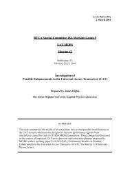
2.2.3 Ground Uplink Message<br />
The <strong>UAT</strong> Ground Uplink message is a general purpose mechanism used primarily <strong>for</strong> the<br />
uplink of FIS data. Each Ground Uplink message contains a 432 byte payload field. The<br />
Ground Uplink Payload is composed of an eight-byte <strong>UAT</strong>-Specific Header, followed by<br />
424 bytes of Application Data. The <strong>UAT</strong> Ground Uplink message header <strong>for</strong>mat is<br />
defined in Section 2.2.3.2 of [<strong>UAT</strong> MOPS]. The Application Data field is composed of<br />
one or more In<strong>for</strong>mation Frames (I-Frames). The decomposition of the Ground Uplink<br />
message payload is shown in Figure 2-1.<br />
Note: In<strong>for</strong>mation in Sections 2.2.3.2 through 2.2.3.3 below will be incorporated in<br />
the next update to [<strong>UAT</strong> MOPS]<br />
Note: An aggregate net throughput (after overhead) of 108 Kbps is available to be<br />
shared among all ground stations. It is expected that most of this will be<br />
available <strong>for</strong> FIS products. This guidance does not address the<br />
prioritization of product distribution or quality of service.
8 bytes<br />
<strong>UAT</strong> -Specific Header<br />
I-Frame 1 I-Frame 2 I-Frame 3<br />
Length<br />
9 bits<br />
Res.<br />
3 bits 4 bits<br />
Transmission order<br />
2.2.3.1 <strong>UAT</strong>-Specific Header<br />
Frame Type<br />
432 bytes (message payload)<br />
424 bytes<br />
Application Data<br />
. . .<br />
Frame Data<br />
Length<br />
I-Frame N<br />
Figure 2-1: Decomposition of the Ground Uplink Message Payload<br />
15<br />
fill as needed<br />
The <strong>UAT</strong>-Specific Header is an 8-byte field that contains in<strong>for</strong>mation on the location of<br />
the broadcasting ground station, the time slot used to send the present message, validity<br />
flags <strong>for</strong> position, time, and application data, and other fields as described in Section<br />
2.2.3.2.2 of [<strong>UAT</strong> MOPS].<br />
2.2.3.2 Application Data<br />
The Application Data is a fixed-length field of 424 bytes. The Application Data consists of<br />
In<strong>for</strong>mation Frames, and always consists of an integral number of bytes. Any remaining<br />
unused portion of the field is zero-filled (i.e., all bits set to ZERO).<br />
Note: The Application Data should be discarded if the Application Data Valid field<br />
is set to “0” in the <strong>UAT</strong>-Specific Header, as specified in [<strong>UAT</strong> MOPS].<br />
2.2.3.3 In<strong>for</strong>mation Frames<br />
Each In<strong>for</strong>mation Frame consists of ‘N’ bytes, comprising four fields <strong>for</strong>matted as shown<br />
in Table 2-1.
16<br />
Table 2-1: Frame Structure<br />
Byte # Bit 1 Bit 2 Bit 3 Bit 4 Bit 5 Bit 6 Bit 7 Bit 8<br />
1 MSB Length<br />
2<br />
3<br />
LSB Reserved MSB Frame Type LSB<br />
-<br />
N<br />
Frame Data<br />
Notes:<br />
2.2.3.3.1 Length Field<br />
1. Byte numbers in this table are relative to the beginning of the current<br />
In<strong>for</strong>mation Frame.<br />
2. Within each byte, bit 1 is transmitted first and bit 8 is transmitted last<br />
The Length field (Byte 1: Bit 1 through Byte 2: Bit 1) is a 9-bit field that contains the<br />
length of the Frame Data field in bytes. Values range from 0 through 422 (decimal). The<br />
Length value is always equal to ‘N-2’.<br />
Note: When In<strong>for</strong>mation Frames do not fully occupy the Application Data field, the<br />
unused portion is zero filled. When encountered by the frame parsing logic,<br />
the zero fill portion will appear as a frame of zero bytes in length or an<br />
incomplete frame if less than 2 bytes remain. This would be the indication to<br />
the parsing logic that the last frame has been found.<br />
2.2.3.3.2 Reserved Field<br />
The Reserved field (Byte 2: Bits 2 through 4) is a 3-bit field that is reserved <strong>for</strong> future<br />
use, and will be set to ALL ZEROES.<br />
2.2.3.3.3 Frame Type Field<br />
The Frame Type field (Byte 2: Bits 5 through 8) is a 4-bit field that contains the indication<br />
<strong>for</strong> the <strong>for</strong>mat of the Frame Data field. The Frame Types are defined in Table 2-2.<br />
MSb<br />
Table 2-2: Frame Types<br />
Value (binary)<br />
LSb<br />
Frame Data Format<br />
0000 FIS-B APDU<br />
0001 - 1110 Reserved <strong>for</strong> future use<br />
1111 TIS-B Signaling 1<br />
1 This entry is labeled as “Reserved <strong>for</strong> developmental use” in the proposed update to [<strong>UAT</strong> MOPS]).
When the Frame Type is the binary value “0000”, the Frame Data contains FIS-B data<br />
packaged as an Application Protocol Data Unit (APDU) as described in Section 3.6, and<br />
Appendix D of [FIS-B MASPS]. When the Frame Type is the binary value “1111”, the<br />
Frame Data contains TIS-B signaling in<strong>for</strong>mation (see Section 4.1.3.2.1). Fourteen<br />
reserved values remain <strong>for</strong> future use.<br />
2.2.3.3.4 Frame Data Field<br />
The Frame Data field conveys the basic units of uplink application data. For FIS-B this<br />
data unit is known as the Application Protocol Data Unit (APDU) as defined in [FIS-B<br />
MASPS].<br />
2.3 FIS Product Encoding (APDUs)<br />
Each APDU will be transmitted <strong>with</strong> an APDU Header followed by the APDU Payload.<br />
2.3.1 APDU Header<br />
The APDU header <strong>for</strong>mat <strong>with</strong> options is as described in Appendix D of [FIS-B MASPS]<br />
<strong>with</strong> one exception as described below.<br />
The over-air <strong>for</strong>mat of the APDU header does not include the 16 bit FIS-B APDU ID<br />
field. Per [FIS-B MASPS], this field is a fixed two byte field of 0xFF and 0xFE. Since<br />
FIS-B APDUs are fully identified as such by the Frame Type field (Section 2.2.3.3.3),<br />
transmission of these 2 bytes over the air interface are unnecessary. If this two byte field<br />
is required <strong>for</strong> interoperability reasons on board the aircraft, this two byte field can be<br />
reconstituted after receipt onboard.<br />
2.3.2 APDU Payload<br />
APDUs will carry products that are registered in the FAA’s FIS-B product registry. This<br />
registry is maintained by the Weather Processor and Sensors Group at the FAA’s William<br />
J. Hughes Technical Center. The registry can be accessed at http://fpr.tc.faa.gov.<br />
The FAA Broadcast Services ground system presently encodes FIS data <strong>for</strong> uplink using<br />
only independent APDUs as described in [FIS-B MASPS]. In the event that future FIS-<br />
B products require an APDU longer than 422 bytes, then the linked APDUs described in<br />
[FIS-B MASPS] may be used.<br />
Two important characteristics of these APDUs are as follows:<br />
• Each independent APDU stands alone in that each individual APDU received<br />
results in some data that can be rendered on the cockpit display; there is no<br />
dependence on the APDUs that precede or succeed it.<br />
• Applications have no need to know which ground station was the one that<br />
uplinked an APDU; the APDU Application Data is ground station independent.<br />
17
18<br />
2.3.3 Initial Products<br />
2.3.3.1 Textual METAR and TAF Products<br />
The Textual METAR and TAF products will use the <strong>for</strong>mat identified in the FIS-B<br />
product registry by the name “Generic Textual Data Product - Type 2 (DLAC)” and the<br />
11 bit Product ID of “413” (decimal). Details on the encoding of the text records are<br />
found in the FAA’s FIS-B product registry (http://fpr.tc.faa.gov).<br />
2.3.3.2 NEXRAD Graphic Product<br />
The NEXRAD Graphic product is identified in the FIS-B product registry by the name<br />
“Global Block Representation – NEXRAD, Type 4 – 8 Level” and the 11 bit Product ID<br />
of “63” (decimal). Details on the encoding of the text records are found in the FAA’s<br />
FIS-B product registry (http://fpr.tc.faa.gov).<br />
2.3.4 Future Products<br />
Bandwidth exists to accommodate additional products and FAA has plans to implement<br />
additional products. FAA will announce the availability of new products when they are<br />
ready <strong>for</strong> operational use. New products will be described in the FAA FIS-B product<br />
registry.
3 Report Interface <strong>Guidance</strong><br />
3.1 Background<br />
This Section provides an example report interface <strong>for</strong>mat <strong>for</strong> the <strong>UAT</strong> equipment.<br />
Specifically, this is the report interface between the <strong>UAT</strong> <strong>Avionics</strong> and the Application<br />
<strong>Avionics</strong> to provide reports that are a direct result of messages received over the <strong>UAT</strong> air<br />
interface 1 . This guidance is targeted primarily <strong>for</strong> general aviation implementations to<br />
foster an open report output interface <strong>for</strong> <strong>UAT</strong> radio equipment<br />
This Section describes a reference interface comprising a set of application-level reports<br />
that are constructed using a standardized packet <strong>for</strong>mat. Also presented is an example of<br />
this interface <strong>with</strong> link-layer encapsulation using frames based on an HDLC <strong>for</strong>mat. This<br />
reference interface provides <strong>for</strong> delivery of received ADS-B and TIS-B traffic, ADS-B<br />
ownship position, and FIS-B uplinks to Application <strong>Avionics</strong>.<br />
Note: This guidance does not apply to integrated implementations where no external<br />
interface is required.<br />
3.2 Composing “Reports”<br />
The <strong>UAT</strong> report assembly function is implemented as a “pipeline” <strong>for</strong> delivery of<br />
message payloads received via the <strong>UAT</strong> <strong>Avionics</strong> and augmented <strong>with</strong> appropriate report<br />
fields.<br />
As indicated in Section 2.2.9 of [<strong>UAT</strong> MOPS], the Time of Message Receipt (TOMR)<br />
field is added to the received in<strong>for</strong>mation by the <strong>UAT</strong> equipment. TOMR has sufficient<br />
resolution and span to resolve the time reference <strong>for</strong> the received message. Absolute<br />
time is not necessary if the Application <strong>Avionics</strong> has access to its own absolute time<br />
reference. The TOMR value is the high-accuracy time measurement <strong>with</strong>in the current<br />
second, which may be used by an external application <strong>for</strong> range measurement and<br />
validation.<br />
3.3 Report Packet Format<br />
Table 3-1 shows the recommended definition of a report packet <strong>for</strong>mat and Table 3-2<br />
shows the recommended set of report packet types.<br />
1 The “report” interface is essentially one way from the <strong>UAT</strong> <strong>Avionics</strong> to the Application <strong>Avionics</strong>. Various required inputs to<br />
the <strong>UAT</strong> <strong>Avionics</strong> (e.g., position, velocity, time etc) are not addressed here even though they may share the same physical<br />
interface <strong>with</strong> the report interface.<br />
19
20<br />
Notes:<br />
Table 3-1: Report Packet Format<br />
# of Bytes Content<br />
1 Packet Type (defined in Table 3-2 below)<br />
4 Time of Message Receipt<br />
(units of hundreds of nanoseconds since UTC midnight modulo 25.6 seconds)<br />
Variable <strong>UAT</strong> Message Payload (see Table 3-2 below)<br />
1. Fields are listed in order of transmission.<br />
2. Multi-byte fields are transmitted most significant byte first.<br />
Packet Type<br />
#<br />
Notes:<br />
Table 3-2: Report Packet Types<br />
Report Packet Type Content<br />
0 Status Periodic status report of <strong>UAT</strong> per<strong>for</strong>mance (Note 1)<br />
1<br />
2<br />
3<br />
4-127<br />
3.4 Link Layer<br />
Traffic Report resulting from<br />
ADS-B message reception by<br />
<strong>UAT</strong> <strong>Avionics</strong> (Note 2)<br />
Ownship Report resulting from<br />
ADS-B message transmission by<br />
<strong>UAT</strong> <strong>Avionics</strong><br />
Ground Uplink Report resulting<br />
Ground Uplink message<br />
reception by <strong>UAT</strong> <strong>Avionics</strong><br />
Reserved <strong>for</strong> manufacturerspecific<br />
packets<br />
18 or 34 bytes, <strong>for</strong>mat as defined in Table 2-8 of<br />
[<strong>UAT</strong> MOPS].<br />
18 or 34 bytes, <strong>for</strong>mat as defined in Table 2-8 of<br />
[<strong>UAT</strong> MOPS].<br />
432 bytes of payload data; header <strong>for</strong>mat as defined<br />
in Table 2-4 of [<strong>UAT</strong> MOPS]. Application Data is<br />
composed of I Frames per Section 2.2.3.3.<br />
1. Items that may be included in the Status Packet Type include: GPS time in<br />
seconds since midnight (full resolution), number of ADS-B and Uplink messages<br />
decoded successfully, and the number of reports discarded in the previous<br />
second due to report interface capacity. No operational use of any in<strong>for</strong>mation<br />
that may be provided in a Status report is being recommended in this document.<br />
2. Traffic Reports include both ADS-B received direct air-air and TIS-B received<br />
ground-air.<br />
The example data link layer frame <strong>for</strong>mat is based on the High-level Data Link Control<br />
(HDLC) link frame as shown in Table 3-3. Transmission using byte-orientation is<br />
recommended in order to support asynchronous serial communications (this relates to the<br />
procedures used <strong>for</strong> “data transparency”—see Section 3.4.1). Each field in Table 3-3 is
discussed in the following subsections to determine its applicability in implementing the<br />
Report Interface.<br />
Note: The link layer frame <strong>for</strong>mat based on HDLC described in this section <strong>for</strong> the<br />
<strong>UAT</strong> report interface is distinct from the In<strong>for</strong>mation Frame <strong>for</strong>mat used<br />
<strong>with</strong>in the Application Data field of the <strong>UAT</strong> Ground Uplink message.<br />
Flag<br />
(Section 3.4.1)<br />
3.4.1 Flag Field<br />
Table 3-3: Typical HDLC Link Layer Frame Format<br />
Address<br />
(Section 3.4.2)<br />
Link Control<br />
(Section 3.4.3)<br />
In<strong>for</strong>mation<br />
(Section 3.4.4)<br />
FCS<br />
(Section 3.4.5)<br />
<strong>21</strong><br />
Flag<br />
(Section 3.4.1)<br />
1 byte 1-4 or 8 bytes 1 byte N bytes 2 bytes 1 byte<br />
The frame starts and ends <strong>with</strong> a “Flag” octet, which is used <strong>for</strong> framing. The flag octets<br />
have the value “01111110” binary. [FIS-B MASPS] provides <strong>for</strong> two alternative<br />
procedures <strong>for</strong> ensuring data transparency (i.e., dealing <strong>with</strong> occurrences of the flag octet<br />
<strong>with</strong>in the frame). The procedure designed to support asynchronous (byte-oriented)<br />
transmission is the method recommended. This asynchronous data transparency<br />
procedure is described in Section 3.4.3.2 of [FIS-B MASPS].<br />
3.4.2 Address Field<br />
Since this link layer is likely to be supporting a dedicated point-point connection between<br />
the <strong>UAT</strong> <strong>Avionics</strong> and the Application <strong>Avionics</strong>, address in<strong>for</strong>mation is not required to<br />
support the data transfer.<br />
Note: The Address Field in a minimal <strong>for</strong>m may be included to maintain compatibility<br />
<strong>with</strong> standard frame <strong>for</strong>mat<br />
3.4.3 Link Control Field<br />
One encoding of the Link Control Field is to identify an Un-numbered In<strong>for</strong>mation (UI)<br />
frame. The <strong>UAT</strong> equipment interface is only required to support UI frames, since the<br />
<strong>UAT</strong> datalink is inherently suited <strong>for</strong> only data broadcasts. There<strong>for</strong>e, it is recommended<br />
that inclusion of a Link Control Field in the report interface is not necessary.<br />
Note: The Link Control Field may be included to maintain compatibility <strong>with</strong><br />
standard frame <strong>for</strong>mat.<br />
3.4.4 In<strong>for</strong>mation Field<br />
The report packets defined in Section 3.3 above represent the In<strong>for</strong>mation Field of the<br />
HDLC link layer frame. One report packet is conveyed in each link layer frame.<br />
3.4.5 Frame Check Sequence<br />
This field contains the two octet Frame Check Sequence specified in [FIS-B MASPS].
22<br />
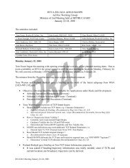
3.4.6 Example Link Layer Frame Format<br />
Figure 3-1 shows the example link layer frame <strong>for</strong>mat <strong>for</strong> the <strong>UAT</strong> report interface.<br />
Flag<br />
(Section 3.4.1)<br />
1 byte<br />
Packet Type<br />
(Table 3-2)<br />
1 byte<br />
In<strong>for</strong>mation<br />
(Section 3.4.4)<br />
N bytes<br />
TOMR<br />
(Section 2.2.9 of<br />
<strong>UAT</strong> MOPS)<br />
4 bytes<br />
FCS<br />
(Section 3.4.5)<br />
2 bytes<br />
N-5 bytes<br />
Flag<br />
(Section 3.4.1)<br />
1 byte<br />
<strong>UAT</strong> Message Payload<br />
Figure 3-1: Example Link Layer Frame Format <strong>for</strong> <strong>UAT</strong> Report Interface
4 Display Interface <strong>Guidance</strong><br />
This section provides guidance <strong>for</strong> the display of surveillance and FIS data when used in<br />
an advisory context. This guidance is limited to some few aspects not yet addressed by<br />
existing standards.<br />
4.1 Considerations <strong>for</strong> Display of Traffic<br />
Traffic in<strong>for</strong>mation on a cockpit display can come from ADS-B and TIS-B<br />
simultaneously. Considerations <strong>for</strong> the processing and display of ADS-B and TIS-B are<br />
provided in this section.<br />
4.1.1 Associating ADS-B and TIS-B Reports<br />
Normally the Fundamental TIS-B service will suppress TIS-B reports representing traffic<br />
that are transmitting ADS-B. One exception is the case when an ADS-B equipped target<br />
is in surveillance coverage, but in an area of marginal or no radio frequency (RF)<br />
coverage <strong>for</strong> the <strong>UAT</strong> ground station network. In order to deal <strong>with</strong> such exception<br />
cases, it is recommended that avionics attempt to prevent the depiction of duplicate target<br />
symbols <strong>for</strong> the same traffic. Specifically, it is desirable to check each TIS-B message<br />
reception to ensure it is not representing traffic that is being received via direct ADS-B<br />
air-air. This is because ADS-B messages will generally be more accurate and have less<br />
latency than the corresponding TIS-B message. Preventing the TIS-B message reception<br />
from “updating” a recent ADS-B reception (i.e., <strong>with</strong>in 5 seconds) will help maintain<br />
stability of the displayed traffic symbol.<br />
Note: Specific detailed requirements on the correlation of TIS-B and ADS-B targets<br />
will be specified in the upcoming ASA MOPS being produced by RTCA.<br />
General requirements from [ASA MASPS] should be considered.<br />
4.1.2 Recommendations <strong>for</strong> Traffic Symbology and Updating<br />
See [ASA MASPS] section 3.3.3 <strong>for</strong> guidance on CDTI displays. See [ASA MASPS]<br />
Section 2 and Table 2-3 <strong>for</strong> requirements on traffic in<strong>for</strong>mation integrity, accuracy, etc.<br />
supporting enhanced visual acquisition, conflict detection, and airport surface situational<br />
awareness.<br />
Note: The upcoming ASAS MOPS will provide further detail on CDTI requirements.<br />
The following is a list of additional recommendations <strong>for</strong> the display and updating of traffic<br />
in<strong>for</strong>mation.<br />
• FAA ground stations may broadcast ADS-B messages <strong>with</strong> an ADDRESS<br />
QUALIFIER field indicating “Fixed ADS-B Beacons”. This would usually be at<br />
low power <strong>for</strong> purposes of monitoring the ground infrastructure. Any receptions<br />
of Fixed ADS-B Beacons by avionics need not be displayed on the traffic display.<br />
• Symbols representing obstacles should be distinct from those representing aircraft<br />
or surface vehicles.<br />
23
24<br />
4.1.3 Special Considerations <strong>for</strong> TIS-B Traffic<br />
TIS-B is a set of surveillance services that derives traffic in<strong>for</strong>mation from one or more<br />
ground surveillance sources and broadcasts to ADS-B equipped aircraft or surface<br />
vehicles. The TIS-B system physical architecture is expected to include both regional<br />
control facilities and ground broadcast stations. TIS-B control facilities are where<br />
surveillance processing and report generation and distribution are per<strong>for</strong>med <strong>for</strong> the TIS-B<br />
system, such that all targets are registered relative to each other (i.e., “fused” in areas of<br />
sensor overlap) and are identified uniquely. TIS-B services will be available where there<br />
is both adequate surveillance coverage from ground sensors and adequate Radio<br />
Frequency (RF) coverage from ground broadcast stations. The TIS-B service will uplink<br />
individual messages in the <strong>UAT</strong> ADS-B message <strong>for</strong>mat—one or more <strong>for</strong> each TIS-B<br />
target update—consistent <strong>with</strong> the <strong>for</strong>mat description in [<strong>UAT</strong> MOPS].<br />
4.1.3.1 Spatial and Temporal Redundancy of Uplinked TIS-B Messages<br />
The Fundamental TIS-B service will use the FAA’s existing network of surveillance<br />
sensors—en route and terminal radar systems 1 . All surveillance sensors <strong>with</strong>in the area<br />
of a regional control facility will be “fused” into a single traffic picture by a fusion tracker<br />
system at the control facility. A TIS-B Server will provide a stream of TIS-B reports to<br />
each individual ground station in the area via an appropriate filtering mechanism. In areas<br />
rich in ground stations and surveillance sensors, a key objective of the filtering mechanism<br />
is to carefully tailor the TIS-B traffic in<strong>for</strong>mation sent to each ground station such that<br />
there is limited overlap (i.e., spatial redundancy) to maintain continuity of service when<br />
transitioning between ground stations. This spatial redundancy is carefully limited because<br />
it adds self interference to the data link system as seen by an aircraft at altitude. The<br />
ground system will generally provide an overlap region <strong>for</strong> TIS-B traffic in<strong>for</strong>mation<br />
between adjacent ground stations of 5-10 NM.<br />
In some situations, each <strong>UAT</strong> ground station may make multiple transmissions of the<br />
same TIS-B message to provide temporal redundancy. This “repeat” procedure will be<br />
most useful in situations where radar surveillance inputs to TIS-B are infrequent (e.g.,<br />
long range radars), making successful receipt of each update by the TIS-B customer<br />
more important. The TIS-B Control Facility will make a best ef<strong>for</strong>t to transmit all copies<br />
of the same TIS-B Report in the same <strong>UAT</strong> epoch so that they have a common Time of<br />
Applicability as perceived by the <strong>UAT</strong> avionics.<br />
Considerations <strong>for</strong> the Application <strong>Avionics</strong> in dealing <strong>with</strong> both spatial and temporal<br />
redundancy are listed below:<br />
• The message payloads of redundant TIS-B messages will be totally identical and<br />
are there<strong>for</strong>e easily identified as such by the Application <strong>Avionics</strong>. Specifically,<br />
no position extrapolation is per<strong>for</strong>med in the ground system.<br />
1 The term “TIS-B” encompasses the rebroadcast of ADS-B from one data link to the other (i.e., from 1090 Extended Squitter to<br />
<strong>UAT</strong> and vice versa). However, the paragraphs that follow are limited in scope to TIS-B when it provides surveillance based on<br />
radar.
• For repeat transmissions, there is a small risk that one or more of the redundant<br />
transmissions will be received in the <strong>UAT</strong> epoch that is one second later than the<br />
true Time of Applicability. The avionics will not be able to detect this condition<br />
absent receipt of the original transmission in the applicable second. This may limit<br />
the ADS-B applications <strong>for</strong> which the initial TIS-B service can be certified.<br />
Note: Identifying and discarding redundant messages will improve the display of<br />
TIS-B traffic when the Application <strong>Avionics</strong> displays extrapolated positions<br />
between actual updates as required by [ASA MASPS].<br />
4.1.3.2 Providing the Pilot an Indication of TIS-B Service Status<br />
In certain TIS-B service areas, the FAA will be able to provide a relatively<br />
comprehensive traffic in<strong>for</strong>mation picture to pilots via TIS-B. For this reason, it is highly<br />
desirable <strong>for</strong> the TIS-B system to support a TIS-B service status indication so that pilots<br />
will know when the traffic picture in the immediate proximity can be expected to be<br />
reasonably complete and when there should be no such expectation. This section<br />
describes the concept along <strong>with</strong> recommended procedures <strong>for</strong> the avionics to provide the<br />
service status indication to the pilot. No similar expectation of a relatively complete traffic<br />
picture can exist <strong>for</strong> ADS-B (<strong>for</strong> some time at least) due to its dependence on ADS-B<br />
equipage.<br />
Note: The TIS-B service will not provide in<strong>for</strong>mation on traffic that is not visible to<br />
the ground surveillance system, i.e., unequipped aircraft.<br />
4.1.3.2.1 TIS-B Signaling<br />
TIS-B messages are not needed to represent traffic that is ADS-B equipped since it is<br />
assumed that ADS-B equipped traffic will be adequately represented via direct air-air<br />
ADS-B reception. However, the TIS-B ground system will uplink TIS-B signaling<br />
in<strong>for</strong>mation <strong>for</strong> ADS-B equipped aircraft—at a low average rate—<strong>for</strong> the purpose of<br />
providing a service status indication. The only signal type defined at this time will be<br />
referred to as a “heartbeat” signal. The heartbeat signal is provided periodically as a<br />
positive indication to the TIS-B customer that TIS-B service is available. Conversely,<br />
lack of any heartbeat signal <strong>for</strong> a certain interval—referred to as the<br />
HEARTBEAT_TIMEOUT interval—indicates that service is NOT AVAILABLE.<br />
The heartbeat signal is conveyed in the <strong>UAT</strong> Ground Uplink message as a list of TIS-B<br />
customer addresses to which the signal pertains. The frame type identifier “15” is used<br />
<strong>for</strong> this purpose (see Table 2-2). Four bytes are used to represent each heartbeat signal<br />
and individual heartbeat signals are packed sequentially <strong>for</strong> uplink into the Frame Data<br />
portion of the In<strong>for</strong>mation Frame as described in Section 2.2.3.3. The <strong>for</strong>mat of an<br />
individual TIS-B signal is shown in Table 4-1. A single Ground Uplink message could<br />
convey a maximum of 105 TIS-B signals if all payload of the Ground Uplink message is<br />
used <strong>for</strong> signaling. This assumes all 105 signals were packed into a single In<strong>for</strong>mation<br />
Frame.<br />
25
26<br />
Transmn<br />
order<br />
1 st<br />
2 nd<br />
3 rd<br />
4 th<br />
Table 4-1: Format of Individual TIS-B Signal<br />
Bit 1 Bit 2 Bit 3 Bit 4 Bit 5 Bit 6 Bit 7 Bit 8<br />
Reserved<br />
(MSB)A1 A2 A3 . . .<br />
Address<br />
.<br />
.<br />
Sig.<br />
Type<br />
Address Qualifier<br />
. . . A22 A23 A24 (LSB)<br />
When the SIGNAL TYPE bit is “1”, the signal is a heartbeat signal: service is available.<br />
When the SIGNAL TYPE bit is “0”, the signal is a “goodbye” signal: service is not<br />
available. Initially, the ground system will provide only the “heartbeat” signal. Section<br />
4.1.3.2.2. on avionics processing uses the heartbeat signal only.<br />
The presence of a heartbeat signal <strong>for</strong> a TIS-B customer indicates that TIS-B service<br />
should be available <strong>for</strong> traffic in the immediate proximity. Upon entry into airspace where<br />
the TIS-B system has both surveillance coverage AND <strong>UAT</strong> ground station coverage<br />
(i.e., ADS-B downlinks received), heartbeat messages are transmitted. To aid the TIS-B<br />
customer to initially acquire their heartbeat messages, the transmission rate may initially<br />
be high <strong>for</strong> a short period (e.g., a rate similar to TIS-B message rate used to represent<br />
traffic). Subsequently, the rate is decreased to a low rate used only to “hold up” the<br />
service available indication. This low rate would be established to ensure at least one<br />
heartbeat reception by the TIS-B customer every HEARTBEAT_TIMEOUT seconds. It<br />
is recommended that avionics treat the HEARTBEAT_TIMEOUT as a parameter <strong>with</strong> a<br />
factory default of 60 seconds.<br />
Note: As experience is gained <strong>with</strong> the TIS-B service, it may be desirable to use a<br />
timeout value other than the default. In the future, it is expected that the<br />
TIS-B function will broadcast a HEARTBEAT_TIMEOUT value that would<br />
override the default.<br />
4.1.3.2.2 <strong>Avionics</strong> Processing to Determine TIS-B Service Status<br />
It is recommended that at least the two TIS-B service status indications listed in Table 4-2<br />
are supported.<br />
Table 4-2: TIS-B Service Status Indications<br />
TIS-B Service Status<br />
Meaning<br />
Indication<br />
“AVAILABLE”* TIS-B customer can expect updates on traffic in the immediate<br />
proximity <strong>with</strong> reasonable confidence.<br />
“NO SVC”* TIS-B customer should not expect updates on traffic in the<br />
immediate proximity<br />
* These are example annunciations only; any equivalent annunciations that convey the<br />
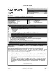
intended meaning may be used
Figure 4-1 illustrates the conditions <strong>for</strong> both of the service status indications relative to the<br />
TIS-B Service Volume. The term “TIS-B Service Volume” as used in this document<br />
represents the intersection of the Surveillance Coverage Volume and the <strong>UAT</strong> Ground<br />
Station Service Volume where these latter terms in italics are described in [TIS-B<br />
MASPS].<br />
TIS-B Service Volume<br />
LOS Limit<br />
“AVAILABLE”<br />
“NO SVC”<br />
Figure 4-1: Illustration of TIS-B Service Status<br />
While Figure 4-1 shows the customer aircraft exiting service through a lateral boundary in<br />
the TIS-B service volume, a more typical case is likely to be when the customer aircraft<br />
descends through the line-of-sight floor of the TIS-B service volume. This could be a<br />
common situation when a <strong>UAT</strong> ground station is sited at an airport location where the<br />
nearest surveillance radar is some distance away. Figure 4-2 shows this case.<br />
ADS-B To Control Facility<br />
TIS-B Traffic and Signaling<br />
From Control Facility<br />
HEARTBEAT<br />
HEARTBEAT<br />
HEARTBEAT<br />
HEARTBEAT<br />
<strong>UAT</strong> GS<br />
HEARTBEAT<br />
HEARTBEAT<br />
<strong>Flight</strong> Path of TIS-B Customer<br />
X<br />
Heartbeat timeout<br />
Runway at GA airport<br />
27<br />
Approximate Floor of Radar Coverage<br />
Figure 4-2: TIS-B Customer Leaving Service Through Floor of Radar Coverage
28<br />
Most of the processing to support the TIS-B service status indication is per<strong>for</strong>med by the<br />
TIS-B ground system. Figure 4-3 shows a logic flowchart that would provide the<br />
recommended status indications.<br />
yes<br />
Start<br />
Has less than<br />
HEARTBEAT_TIMEOUT<br />
seconds elapsed since last<br />
TIS-B signal recv’d<br />
<strong>for</strong> ownship<br />
TIS-B Service Status Annunciations<br />
AVAILABLE NO SVC<br />
Wait one second<br />
Figure 4-3: <strong>Avionics</strong> Processing Logic to Support the TIS-B Service Status<br />
Indication<br />
4.1.3.2.3 Additional Points Relative to TIS-B Service Status<br />
This service status approach is designed to provide high confidence of service <strong>for</strong> those<br />
that receive the “AVAILABLE” indication. This is because the TIS-B heartbeat<br />
messages provide confirmation of operation <strong>for</strong> the entire TIS-B system <strong>for</strong> the<br />
customer’s immediate airspace environment. Even in cases where no traffic is visible on<br />
the display, the pilot has reasonable confidence the TIS-B system has no traffic in the<br />
customer’s immediate proximity to depict since the heartbeat message is being provided.<br />
On the other hand, a “NO SVC” indication could result in the pilot still seeing traffic on<br />
the display. This could be <strong>for</strong> either of three reasons: 1) traffic is due to ADS-B air-air<br />
message reception not subject to the service status indication, 2) traffic is due to TIS-B<br />
message reception, but <strong>for</strong> traffic not in the immediate proximity of the TIS-B customer<br />
aircraft, 3) the TIS-B customer is skirting the edge of the TIS-B service volume resulting<br />
in possible intermittent depiction of proximate traffic.<br />
Providing a TIS-B service status indication can be fully supported only <strong>for</strong> TIS-B<br />
customers who are also ADS-B participants.<br />
no
Note: The topic of TIS-B service status indication is expected to be further refined<br />
in the next update to [TIS-B MASPS]. It is possible that when published, the<br />
standards may differ somewhat from the preliminary in<strong>for</strong>mation presented<br />
in this section.<br />
4.2 Consideration <strong>for</strong> Processing and Display of FIS-B Products<br />
<strong>Guidance</strong> applicable to the processing and display of uplinked FIS-B products is provided<br />
in Section 3.8.1 of [FIS-B MASPS].<br />
One additional set of guidance beyond [FIS-B MASPS section 3.8.1] is applicable to the<br />
NEXRAD Graphics Product discussed in Section 2.3.3.2. If the cockpit display of the<br />
NEXRAD Graphics product is updated in an incremental fashion, the following guidelines<br />
apply (i.e., as APDUs <strong>with</strong> new data (later observation time or cut-off time) are received,<br />
they are integrated directly into the cockpit display, replacing that incremental portion of<br />
the display contained in that APDU):<br />
� The product time displayed shall be the time of the oldest source product (mosaic<br />
or individual observation) that contributes to the displayed image.<br />
� The time span between the oldest and newest source product contributing to the<br />
displayed image shall not exceed 10 minutes. Portions of the image that exceed<br />
this 10 minute requirement shall be depicted as missing data.<br />
� This incremental display technique should not be used as the basis <strong>for</strong> a<br />
Sequential or Looping Product.<br />
Note: This guidance seeks to limit the maximum age difference of the data<br />
contained in these displays. This guidance will be included in the next<br />
update to [FIS-B MASPS].<br />
29
30<br />
5 Acronyms<br />
ACL ASA Capability Level<br />
ADS-B Automatic Dependent Surveillance-Broadcast<br />
APDU Application Protocol Data Unit<br />
ASA Aircraft Surveillance Applications<br />
ASAS Airborne Separation Assistance System<br />
ASSAP Airborne Surveillance and Separation Assurance Processing<br />
ATC Air Traffic Control<br />
CDTI Cockpit Display of Traffic In<strong>for</strong>mation<br />
CFR Code of Federal Regulations<br />
DLAC Data Link Application Coding<br />
FCS Frame Check Sequence<br />
FIS <strong>Flight</strong> In<strong>for</strong>mation Services<br />
FIS-B <strong>Flight</strong> In<strong>for</strong>mation Services-Broadcast<br />
GSA Ground Surveillance Applications<br />
HDLC High Level Datalink Control<br />
ICAO International Civil Aviation Organization<br />
IMC Instrument Meteorological Conditions<br />
MASPS Minimum Aviation System Per<strong>for</strong>mance Standards<br />
MCDU Multi-function Control Display Unit<br />
METAR Meteorological Aviation Report<br />
MOPS Minimum Operational Per<strong>for</strong>mance Standard<br />
NEXRAD Next Generation Weather Radar<br />
NOTAM Notice to Airmen<br />
RF Radio Frequency<br />
SAE Society of Automotive Engineering<br />
SF<strong>21</strong> <strong>Safe</strong><strong>Flight</strong> <strong>21</strong><br />
SSR Secondary Surveillance Radar<br />
SUA Special Use Airspace<br />
TAF Terminal Area Forecasts<br />
TIS-B Traffic In<strong>for</strong>mation Services-Broadcast<br />
TOMR Time of Message Receipt<br />
<strong>UAT</strong> Universal Access Transceiver<br />
UI Un-numbered Info<br />
UTC Universal Time Coordinated