Appendix B: Use of RNP Flight Management System Navigation ...
Appendix B: Use of RNP Flight Management System Navigation ...
Appendix B: Use of RNP Flight Management System Navigation ...

Create successful ePaper yourself
Turn your PDF publications into a flip-book with our unique Google optimized e-Paper software.
<strong>Appendix</strong> B: <strong>Use</strong> <strong>of</strong> <strong>RNP</strong> <strong>Flight</strong> <strong>Management</strong> <strong>System</strong><br />
<strong>Navigation</strong> Data as a Backup Source for ADS-B<br />
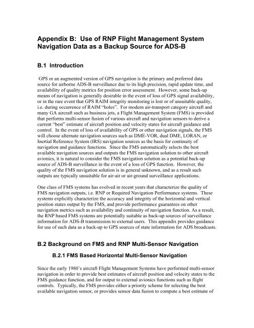
B.1 Introduction<br />
GPS or an augmented version <strong>of</strong> GPS navigation is the primary and preferred data<br />
source for airborne ADS-B surveillance due to its high precision, rapid update time, and<br />
availability <strong>of</strong> quality metrics for position error assessment. However, some back-up<br />
means <strong>of</strong> navigation is generally desirable in the event <strong>of</strong> loss <strong>of</strong> GPS signal availability,<br />
or in the rare event that GPS RAIM integrity monitoring is lost or <strong>of</strong> unsuitable quality,<br />
i.e. during occurrence <strong>of</strong> RAIM “holes”. For modern air-transport category aircraft and<br />
many GA aircraft such as business jets, a <strong>Flight</strong> <strong>Management</strong> <strong>System</strong> (FMS) is provided<br />
that performs multi-sensor fusion <strong>of</strong> various aircraft and navigation sensors to derive a<br />
current “best” estimate <strong>of</strong> aircraft position and velocity states for aircraft guidance and<br />
control. In the event <strong>of</strong> loss <strong>of</strong> availability <strong>of</strong> GPS or other navigation signals, the FMS<br />
will choose alternate navigation sources such as DME-VOR, dual DME, LORAN, or<br />
Inertial Reference <strong>System</strong> (IRS) navigation sources as the basis for continuity <strong>of</strong><br />
navigation and guidance functions. Since the FMS automatically selects the best<br />
available navigation sources and outputs the FMS navigation solution to other aircraft<br />
avionics, it is natural to consider the FMS navigation solution as a potential back-up<br />
source <strong>of</strong> ADS-B surveillance in the event <strong>of</strong> a loss <strong>of</strong> GPS function. However, the<br />
quality <strong>of</strong> the FMS navigation solution is in general unknown, and as a result such<br />
outputs are typically unsuitable for air-air or air-ground surveillance applications.<br />
One class <strong>of</strong> FMS systems has evolved in recent years that characterize the quality <strong>of</strong><br />
FMS navigation outputs, i.e. <strong>RNP</strong> or Required <strong>Navigation</strong> Performance systems. These<br />
systems explicitly characterize the accuracy and integrity <strong>of</strong> the horizontal and vertical<br />
position states output by the FMS, and provide performance guarantees on other<br />
navigation metrics such as availability and continuity <strong>of</strong> navigation function. As a result,<br />
the <strong>RNP</strong> based FMS systems are potentially suitable as back-up sources <strong>of</strong> surveillance<br />
information for ADS-B transmission to external users. This appendix provides guidance<br />
for use <strong>of</strong> such data as a back-up to GPS sources <strong>of</strong> state information for ADS broadcasts.<br />
B.2 Background on FMS and <strong>RNP</strong> Multi-Sensor <strong>Navigation</strong><br />
B.2.1 FMS Based Horizontal Multi-Sensor <strong>Navigation</strong><br />
Since the early 1980’s aircraft <strong>Flight</strong> <strong>Management</strong> <strong>System</strong>s have performed multi-sensor<br />
navigation in order to provide best estimates <strong>of</strong> aircraft position and velocity states to the<br />
FMS guidance function, and for output to external avionics functions such as flight<br />
controls. Typically, the FMS provides either a priority scheme for selecting the best<br />
available navigation sensor, or provides sensor data fusion to compute a best estimate <strong>of</strong>
navigation states given several sensors such as GPS, DME/DME, DME/VOR, and IRS.<br />
In air-transport category aircraft, the IRS system is used as a back-up sensor and is<br />
directly integrated with the other sensor modes, e.g. on current Boeing 737 FMS aircraft<br />
the available sensor modes are GPS/IRS, DME/DME/IRS, DME/VOR/IRS,<br />
LOC/DME/IRS, and IRS (free inertial mode). If the existing navigation signal, say GPS,<br />
is unavailable for some time period, then the IRS system is used to integrate the FMS<br />
navigation solution forward until the GPS signal is available again, or alternately, the<br />
pilot can select another sensor mode such as DME/DME/IRS radio updating if that mode<br />
is available.<br />
Figure 1 shows a typical pilot Control Data Unit (CDU) position reference page for<br />
cockpit display <strong>of</strong> available navigation sources on a Boeing 737 aircraft. The first row <strong>of</strong><br />
data denoted “FMC POS” contains the current aircraft latitude and longitude <strong>of</strong> the FMS<br />
horizontal position vector and ground speed outputs. The next two rows provide the Left<br />
and Right side IRS position and ground speed outputs, followed by the Left and Right<br />
side GPS sensor position outputs. Finally, the preferred means <strong>of</strong> radio updating, i.e.<br />
dual DME or VOR/DME is displayed in the last data row denoted “RADIO”. The pilot<br />
can select or change sensor updating modes, and specify a specific sensor for FMC<br />
position in the event that one <strong>of</strong> the sensors currently used in the FMC calculations is<br />
faulty or unreliable.<br />
Figure B-1: Example Position Reference Page – Boeing 737 CDU<br />
B.2.2 Vertical Channel Integration<br />
The Baro vertical rate output from the Air Data Computer (ADC) has always been noisy<br />
and problematic as a source <strong>of</strong> vertical information for vertical flight controls.<br />
Consequently, the IRS sensor and the ADC are typically integrated in modern FMS
aircraft to provide a more reliable vertical rate signal. One method <strong>of</strong> vertical integration<br />
is to use a complementary filter with input signals consisting <strong>of</strong> Baro altitude and rate,<br />
and IRS vertical acceleration and inertial vertical rate as constituents. Basically, the<br />
complementary filter provides a low-pass smoothing filter on the Baro inputs and acts<br />
As a high-pass filter on the IRS inputs, in order to compensate for Baro filter lag while<br />
simultaneously eliminating altitude bias in the IRS inputs. This integration may take<br />
place in the FMS or as a separate IRS/ADC pre-processor, prior to the FMS calculations.<br />
At any rate, the vertical outputs <strong>of</strong> the FMS are Baro altitude and altitude-rate. As a<br />
consequence, none <strong>of</strong> the geometric vertical outputs <strong>of</strong> the GPS sensors are used in airtransport<br />
category aircraft. For FMS aircraft without IRS sensors, it is possible to<br />
integrate the vertical channel GPS signals and the ADC in a complementary filter<br />
analogous to that described above. In this case, the GPS signals would be used to<br />
calculate an improved Baro vertical rate, and the output <strong>of</strong> the FMS would be the<br />
horizontal GPS states plus complementary filtered Baro altitude and vertical rate.<br />
B.2.3 FMS / <strong>RNP</strong> Based Multi-Sensor <strong>Navigation</strong><br />
<strong>RNP</strong> based FMS systems utilize the precision <strong>of</strong> navigation inherent in modern FMS<br />
systems to fly intended paths within specified lateral or vertical containment regions, and<br />
with other specified navigation performance metrics. Required <strong>Navigation</strong> Performance<br />
(<strong>RNP</strong>) as defined by ICAO document 9650 is a statement <strong>of</strong> navigation system<br />
performance accuracy, integrity, continuity and availability necessary for operations<br />
within a defined airspace. Applications <strong>of</strong> <strong>RNP</strong> to date include the ability to fly precise<br />
lateral paths in mountainous terrain for non-visual approach and departure operations,<br />
precisely specified lateral and vertical paths for noise abatement in urban areas, and<br />
precise lateral containment for procedural separation <strong>of</strong> parallel tracks in en-route /<br />
oceanic airspace. In order to fly these procedures, an airplane must be certified to <strong>RNP</strong><br />
standards consistent with the airspace routings for such procedures. For example, the<br />
Juneau, Alaska <strong>RNP</strong> approach requires an accuracy bound <strong>of</strong> 0.15 nm including<br />
navigation sensor accuracy, and lateral flight technical error. The use <strong>of</strong> <strong>RNP</strong> navigation<br />
replaces specification <strong>of</strong> detailed navigation and flight system hardware with generic<br />
<strong>RNP</strong> requirements, allowing avionics system designers to use different hardware<br />
architectures and avionics integration methods to achieve desired <strong>RNP</strong> levels.<br />
This appendix is primarily concerned with providing guidance for conversion <strong>of</strong> available<br />
<strong>RNP</strong> metrics into accuracy and integrity metrics for ADS-B transmission <strong>of</strong> FMS state<br />
vector data, i.e. STP conversion <strong>of</strong> ANP and <strong>RNP</strong> metrics into HEPU, HEVU, and HPL<br />
(Rc) metrics for ADS-B broadcast <strong>of</strong> FMS position and velocity states.<br />
<strong>RNP</strong> accuracy, denoted <strong>RNP</strong>-X for X nm position accuracy, is a 95% horizontal position<br />
bound centered on the computed FMS position that is required for navigation on a<br />
defined airspace or route segment. <strong>RNP</strong>-X indicates the required accuracy <strong>of</strong> a navigation<br />
system in normal operations, i.e. <strong>RNP</strong>-1 indicates a 1 nm accuracy bound. The actual<br />
navigation performance (ANP) is the computed navigation system accuracy for the FMS<br />
horizontal position and represents a radius <strong>of</strong> a circle centered on the FMS position such<br />
that the aircraft is inside the circle with 95% probability <strong>of</strong> better. The aircraft meets the
current <strong>RNP</strong> accuracy requirement if ANP < <strong>RNP</strong>(X). Note: <strong>RNP</strong>-X is typically selected<br />
by the flight crew for a given region <strong>of</strong> flight, or provided by FMS default values, e.g.<br />
<strong>RNP</strong>-2 for domestic en-route airspace.<br />
<strong>RNP</strong> integrity is represented by a horizontal containment radius (Rc) <strong>of</strong> a circle centered<br />
on the FMS position such that the probability <strong>of</strong> the true position lying outside the circle<br />
without being detected is improbable, i.e. less than 1E^-5 per hour. For <strong>RNP</strong> systems,<br />
pilot alerting <strong>of</strong> inadequate navigation performance is provided whenever ANP exceeds<br />
<strong>RNP</strong>. If ANP < <strong>RNP</strong> then <strong>RNP</strong> integrity is guaranteed at two times <strong>RNP</strong>, i.e. Rc
B.3.1 Overview <strong>of</strong> GPS Primary and FMS Backup Data Source<br />
Selection<br />
The GPS sensor output is generally preferred to using FMS state data, even if the GPS<br />
sensor is the primary <strong>Navigation</strong> sensor used for the FMS <strong>Navigation</strong> solution. There are<br />
several reasons why GPS is preferred: (1) the GPS quality metrics such as HFOM and<br />
HPL are generally more accurate and less conservative than the FMS ANP and <strong>RNP</strong><br />
quality metrics, and (2) the GPS sensor provides a precise estimate <strong>of</strong> time-<strong>of</strong>measurement,<br />
whereas the FMS does not output the measurement time to other avionics<br />
since it outputs state data at a relatively high data rate, e.g. 10 hz data rate for modern<br />
FMS systems. Moreover, on some aircraft, the GPS sensors are not integrated into the<br />
FMS navigation solution, and are primarily used for other functions such as ADS-B<br />
surveillance and enhanced ground proximity warning. In this case, the GPS sensors will<br />
in general produce position estimates that are much more accurate than those derived<br />
using traditional navigation sources such as DME/DME and IRS sensors.<br />
Nonetheless, there are situations where GPS is not available or is not desirable as a data<br />
source for ADS-B use. The latter situation occurs when there are insufficient GPS<br />
satellites for RAIM based integrity monitoring, or the satellite geometry is poor resulting<br />
in large GDOP values and in large HPL values. For navigation functions where high<br />
accuracy is needed, predictive RAIM is generally required so that alternate procedures<br />
can be used during those times when RAIM monitoring is inadequate. However, modern<br />
FMS systems generally can ‘coast through’ such periods using multi-sensor integration<br />
methods to back-up the GPS sensor and assure availability and continuity <strong>of</strong> the<br />
navigation solution, although at a somewhat reduced accuracy level. Consequently, <strong>RNP</strong><br />
based FMS systems that quantify the current accuracy level <strong>of</strong> the navigation solution can<br />
provide a valuable back-up to the GPS sensor in these situations.<br />
The proposed airborne architecture for using GPS and FMS based data sources for ADS-<br />
B is shown in Figure B-3. The GPS data source for ADS-B can be either the same sensor<br />
selected for integration into the aircraft navigation solution, or can be another, standalone<br />
GPS sensor. In any case, the geometric position and velocity states from this GPS and<br />
the GPS accuracy and integrity metrics, e.g. HFOM, VFOM, HPL, and VPL are input<br />
into the STP interface for ADS-B transmission. Baro Altitude is input directly from the<br />
air data computer and is the same sensor output selected by the flight crew for<br />
transponder output <strong>of</strong> pressure altitude. The <strong>Flight</strong> <strong>Management</strong> Computer also inputs<br />
the FMS position and velocity states to the STP function, together with currently<br />
displayed ANP and <strong>RNP</strong>, and the IRS /air data derived Baro vertical rate. In addition to<br />
the primary content from the FMC and other sensor interfaces, additional discrete values<br />
are output indicating validity <strong>of</strong> sensor outputs, type <strong>of</strong> sensor data, if GPS data, whether<br />
WAAS or LAAS capable, and for the FMC output may include bits indicating which<br />
sensors contribute to the selected navigation solution. The STP function then selects the<br />
GPS or FMC horizontal position and velocity, selects either a geometric vertical rate or a<br />
Baro vertical rate for ADS-B transmission, and computes various quality metrics that<br />
determine the state vector metrics NACp, NACv, NIC, and SIL transmitted in the ADS-B<br />
messages. The following sections describe the calculation <strong>of</strong> the quality metrics and the
selection <strong>of</strong> the GPS or FMC states for ADS-B output. Note: Although ANP and <strong>RNP</strong><br />
metrics and other FMC parameters shown below are available on special FMS data buses<br />
for pilot displays, some <strong>of</strong> the parameters shown flowing between the FMC and the STP<br />
function may not be available on current data buses, i.e. using general purpose ARINC<br />
429 data buses.<br />
<strong>Navigation</strong><br />
Data<br />
Sources<br />
•INS<br />
•GPS<br />
•VOR/DME<br />
•Air Data<br />
•LOC<br />
GPS<br />
• (X, V) Geo states<br />
• HFOM, VFOM<br />
•HPL, VPL<br />
Figure B-3: Airborne Architecture for GPS Primary and FMS/<strong>RNP</strong> Backup for ADS-B<br />
Notes: 1) Selected FMC navigation states are output at ~ 10 hz rate with no time mark.<br />
2) Discretes are binary data that may include FMC NAV data sources in use.<br />
3) Quality metrics include HEPU, VEPU*, HPL, VPL*, HEVU, and VEVU*,<br />
where the * (vertical) metrics are not output for FMC selected states .<br />
B.3.2 Calculation <strong>of</strong> Horizontal Accuracy Metric (HEPU) for <strong>RNP</strong><br />
Data Sources<br />
The primary source <strong>of</strong> position accuracy available from the FMS is the ANP metric. For<br />
GPS updating <strong>of</strong> the FMS navigation solution, the ANP metric may be a conservative<br />
estimate <strong>of</strong> HEPU, i.e. for 737 <strong>RNP</strong> based FMS systems, the following bound is valid<br />
when GPS is the primary source <strong>of</strong> horizontal position: HEPU
since the more conservative bound is valid for all <strong>RNP</strong> aircraft types and for all modes <strong>of</strong><br />
FMC navigation updating. Consequently, the ANP metric can be encoded as the estimate<br />
<strong>of</strong> HEPU or ‘EPU’ on an ARINC data bus. If the FMS is selected as the source <strong>of</strong> ADS-<br />
B position, then VEPU is not relevant for NACp encoding since the vertical FMS outputs<br />
are based on pressure altitude, and ANP is then the sole basis for encoding NACp.<br />
B.3.3 Calculation <strong>of</strong> Horizontal Velocity Metric (HEVU) for <strong>RNP</strong><br />
Data Sources<br />
In this document, we recommend that HEVU be limited to a value such that the accuracy<br />
metric NACv =1. The reason is that in the case that GPS is not being used for FMS<br />
position updating, the IRS sensor is likely the primary source <strong>of</strong> horizontal velocity data.<br />
Current IRS sensor accuracy when unaided by external position updating is on the order<br />
<strong>of</strong> 6 m/s (95% probability) or better. This results in a NACv =1 estimate as a worst case<br />
for FMS velocity accuracy. Although it is recommended to simply set HEVU to 6 m/s or<br />
any other value between 3.0 and 10.0 m/s for ADS-B calculation <strong>of</strong> NACv, it is possible<br />
to do somewhat better when GPS updating <strong>of</strong> the FMC navigation solution. In this case,<br />
the calculation <strong>of</strong> HEVU can use the methodology shown in row 1 <strong>of</strong> Table 2.2.4.6-2, i.e.<br />
it is possible to achieve a NACv =2 when GPS updating. However, this means that one<br />
<strong>of</strong> the discrete outputs from the FMC shown in Figure B-3 is an indicator whether GPS<br />
updating occurs or not. Although not recommended due to increased complexity, it is<br />
feasible to use the methodology shown in Table 2.2.4.6-2 with HFOM replaced by ANP<br />
to achieve somewhat smaller HEVU values when GPS updating.<br />
B.3.4 Calculation <strong>of</strong> Horizontal Integrity Metric (HPL / Rc) for<br />
<strong>RNP</strong> Sources<br />
As stated in the previous section B.2.3, the horizontal containment radius Rc for <strong>RNP</strong><br />
based systems is bounded by<br />
Rc
B.3.5 Calculation <strong>of</strong> HEPU, HEVU and HPL for non-<strong>RNP</strong> FMS<br />
Sources<br />
The calculation <strong>of</strong> quality metrics, and in particular integrity for non-<strong>RNP</strong> FMS systems<br />
is somewhat problematic. Nonetheless, for minor level surveillance applications or for<br />
applications where high accuracy is not required, such systems may be used to back-up a<br />
primary or stand-alone GPS sensor. For traditional FMS navigation sources such as dual-<br />
DME and DME-VOR with IRS fall-back, the navigation accuracy <strong>of</strong> such systems can be<br />
estimated or bounded, provided the specific sensor mode in use for navigation is<br />
indicated to the STP module.<br />
For dual DME and DME-VOR systems, one-sigma bounds on horizontal position<br />
accuracy are provided in DO-236B, <strong>Appendix</strong> C. Assuming Gaussian error distributions<br />
on DME and VOR sensor errors, the 95% accuracy metric for these navigation sources<br />
can be estimated using<br />
HEPU = 2* sigma(horizontal position),<br />
where specific equations are provided in the above referenced document for dual DME<br />
and DME-VOR systems, and worst case observation geometries in terms <strong>of</strong> operating<br />
ranges and angular separations can be used to bound the HEPU calculation. A similar<br />
approach can be used for other sensors such as GPS and DME / Localizer navigation<br />
solutions.<br />
The calculation <strong>of</strong> velocity accuracy is similar to that above for <strong>RNP</strong> FMS systems, i.e.<br />
assuming that an IRS sensor is part <strong>of</strong> the FMS navigation solution, then a fixed bound<br />
based on IRS velocity error can be used, e.g. HEVU = 6 m/s for modern Boeing FMS<br />
aircraft.<br />
The calculation <strong>of</strong> HPL or containment radius Rc for non-<strong>RNP</strong> sources is problematic<br />
since integrity is not typically established on the basis <strong>of</strong> a containment metric. However,<br />
it may be possible to compute an upper bound on containment integrity for navigation<br />
sources such as DME, VOR, and LORAN that perform external monitoring <strong>of</strong> signals in<br />
order to validate sensor functioning. For dual DME systems with angular extent between<br />
30 degrees and 150 degrees, and for DME-VOR systems with VOR range not exceeding<br />
20 nm, external sensor monitoring yields a maximum error before sensor shutdown not<br />
exceeding 2 nm. In this case an HPL
say on the order <strong>of</strong> 2*HEPU with SIL=2 integrity level, would be to monitor position<br />
differences from non-<strong>RNP</strong> position sources versus TIS-B, TCAS, or other sensor position<br />
inputs to ASSAP capable <strong>of</strong> independent monitoring <strong>of</strong> aircraft position. Such multisensor<br />
processing may be considered in future standards documents if additional GPS<br />
backup sources are needed for more advanced ADS-B applications.<br />
B.3.6 GPS / FMS Data Source Selection<br />
One or more GNSS sensors and the FMS navigation solution may be sent simultaneously<br />
to the STP function to enhance availability <strong>of</strong> state data for ADS-B transmission. In the<br />
case that there are several data sources, the STP function must select one <strong>of</strong> those sources<br />
for output to the ADS-B transmit function. The recommended data source for horizontal<br />
position and velocity in most cases is the primary GNSS input source as identified by<br />
installation parameters or as selected by the pilot as the primary sensor for aircraft<br />
navigation. If this data source is not available, i.e. the input source is invalid, or if the<br />
containment integrity <strong>of</strong> this source is unknown or substantially larger than that <strong>of</strong><br />
another input source, then an alternate data source should be selected, i.e. another data<br />
source that contains valid state data and has the smallest containment integrity (HPL<br />
metric) <strong>of</strong> the available data sources.<br />
There are several mechanisms that can cause source selection to switch to the FMS or<br />
another GNSS sensor. If the satellite geometry for the GNSS sensors is poor, i.e. there<br />
are insufficient satellites with adequate observation geometry for expected RAIM<br />
performance, then the HPL metric from the GNSS sensor(s) can become very large for<br />
some time period until additional satellites become available for the RAIM calculations.<br />
Such “RAIM holes” can last several minutes, reducing availability and continuity <strong>of</strong><br />
critical ADS-B operations. If an <strong>RNP</strong> based FMS is used as a backup during such<br />
conditions, then continuity <strong>of</strong> ADS-B operations is greatly enhanced. The reason is that<br />
the IRS system acts as a short term backup to the GNSS sensor. For example, during a<br />
RAIM hole or loss <strong>of</strong> GNSS inputs, the typical value <strong>of</strong> ANP for an <strong>RNP</strong> based B-737<br />
aircraft increases at an observed rate <strong>of</strong> about 0.02 nm per minute during such conditions.<br />
This means that accuracies on the order <strong>of</strong> 0.1 nm and containment radius on the order <strong>of</strong><br />
0.2 nm (NIC=7) can be maintained for several minutes during such an event, if the STP<br />
switches from a GNSS sensor to a low <strong>RNP</strong> FMS position source. Similarly, if one or<br />
more GNSS sensors become unavailable due to signal interference or sensor failure, then<br />
ADS-B continuity <strong>of</strong> state data is assured by switching to the FMS source. In the event<br />
<strong>of</strong> an extended duration outage <strong>of</strong> GNSS sensors, the pilot may switch to another<br />
navigation source such as DME/DME/IRS navigation mode and increase the <strong>RNP</strong> value<br />
consistent with the current ANP <strong>of</strong> that data source, e.g. to <strong>RNP</strong> = 0.5 nm if ANP < 0.5<br />
nm. In that case, ADS-B operations could continue after loss <strong>of</strong> the GNSS sensors with<br />
an increased HPL = 2*<strong>RNP</strong>.<br />
The actual algorithm for FMS source selection should be based on position integrity, not<br />
accuracy, since the former is more important for critical separation applications. If<br />
source selection is based on HPL, then a threshold value on the order <strong>of</strong> delta_HPL<br />
>=0.05 nm is recommended for switching from a GNSS source to the FMS output, i.e.
HPL(GPS) >= HPL(FMS) + 0.05 nm. This is to prevent rapid alteration <strong>of</strong> data sources<br />
when the two HPL values are nearly equal. In the event that the FMS source has been<br />
selected for some time, it is recommended to change back to a GNSS data source when<br />
the HPL value for a GNSS source drops below that <strong>of</strong> the FMS. Additional guidance and<br />
requirements on source selection are discussed in section 2.2.3.8 <strong>of</strong> the STP MOPS.<br />
If a GNSS sensor is selected for providing ADS-B state vector outputs, then the<br />
geometric altitude and vertical altitude rate values for that sensor should be selected for<br />
ADS-B transmission. Otherwise, if the FMS navigation states are selected for ADS-B<br />
output, then the vertical rate from the FMS (with pressure vertical rate type indicated to<br />
the ADS-B transmit function) should be selected for ADS-B output. The FMS pressure<br />
altitude is not selected in that case, however, since the air data sensor selected for<br />
transponder altitude is always used, when available, as the basis for ADS-B baro altitude.