PM100P -Power Module Control unit and safety thermostat for ...
PM100P -Power Module Control unit and safety thermostat for ...
PM100P -Power Module Control unit and safety thermostat for ...
- No tags were found...
You also want an ePaper? Increase the reach of your titles
YUMPU automatically turns print PDFs into web optimized ePapers that Google loves.
<strong>PM100P</strong> - <strong>Power</strong> <strong>Module</strong><strong>Control</strong> <strong>unit</strong> <strong>and</strong> <strong>safety</strong> <strong>thermostat</strong> <strong>for</strong> radiant panelinstallationsGIACOMINI s.p.a.•28017 S.Maurizio d’Opaglio (Novara)•Tel. 0322-923111•Fax 0322-96256•www.giacomini.com
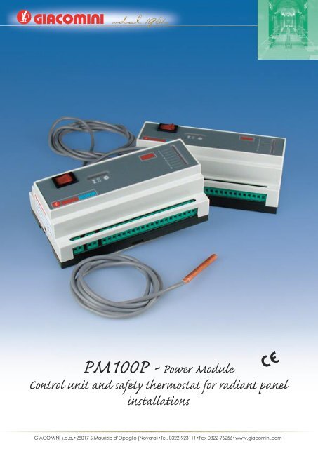
November 2004ISO 9001BSI • Certificate n° FM 00625 • Amendment to 03-10-2000 ICIMCertificate n° 0006/3 • 23-07-2002Technicalcommunication n°12-402GB<strong>PM100P</strong> - <strong>Power</strong> <strong>Module</strong>The <strong>PM100P</strong> control <strong>unit</strong> is designed to beused in radiant panel heating installations,where <strong>for</strong> example:• the control of the supply to the singlecircuits is made by means of electricalactuators without end stroke microswitches,such as Giacomini productsR478 (N.O.) <strong>and</strong> R473 (N.C.) (230V ~);• the control of the maximun delivery temperaturecontrol of the supply to singlecircuits is made by ìfixed pointî mixingsystems (<strong>for</strong> example Giacomini productR557).The basic function the <strong>PM100P</strong> control <strong>unit</strong><strong>for</strong> radiant panel installations is :1.the automatic turning of (or the starting)of the circulation pump according to thecondition of the electrical actuators (R478 or R473 230V~) which are connectedto it;2.<strong>safety</strong> <strong>thermostat</strong> with immersionprobe.Moreover the <strong>PM100P</strong> control <strong>unit</strong> <strong>for</strong>radiant panel installations ensures a rapidconnection to the actuators <strong>and</strong> to the<strong>thermostat</strong>s, without using auxiliary devicessuch as distribution cabinets <strong>and</strong>/orinterface relay.Function• Supply 230V ~±10%• Possibility to manage independentlyup to 8 ìfreeî contacts from ambient<strong>thermostat</strong>s• Possibility to drive up to 16 electricalactuators R478 (N.O.) or R473 (N.C.)at 230V ~ (8 zones) max 2 <strong>for</strong> eachcouple of outlet binding-screys.• Visualization of the control state ofthe actuators, by means of LED indicators• Delay in starting the circulator(- 4 minutes) at the opening of one ofthe hydraulic circuits, after the conditionof complete closing.• Connection <strong>for</strong> the chrono <strong>for</strong> activationof the circulator <strong>and</strong> the electricalactuators, with timer• Integrated line fuse: 6,3A delayed• Line switch with luminous indicator• Dimensions in accordance with DIN43880 St<strong>and</strong>ard .• Suitable <strong>for</strong> installation on DIN EN50022 bar.• Input from <strong>thermostat</strong>s : contactswithout voltage (min.1A @ 230V ~)• Chrono function input : contactwithout voltage (max. 8A @ 230V ~)• Output <strong>for</strong> circulator : contactwithout voltage (10A res.5A ind.) @230V ~)• Additional controlled output : contactwithout voltage (10A res. 5A ind). @230V ~• Connection binding-screws : screwterminal <strong>for</strong> wires of 1.5 mm 2• Protections : IP20• Ambient working conditions : 0˜50∞C;10˜90% R.HU. without condensate• Ambient storage conditions : -20˜70∞C; 10˜90% R.HU. withoutcondensateFeaturesProduct in compliance with the European directives 73/23/CEE (low voltage directive)<strong>and</strong> 93/68/CEE (electromagnetic compatibility directive)
November 2004ISO 9001BSI • Certificate n° FM 00625 • Amendment to 03-10-2000 ICIMCertificate n° 0006/3 • 23-07-2002Technicalcommunication n°12-402GB<strong>PM100P</strong> - <strong>Power</strong> <strong>Module</strong>The <strong>PM100P</strong> control <strong>unit</strong> <strong>for</strong> radiantpanel installations is able to drive theactuators R478 or R473 230V ~, accordingto the condition of the <strong>thermostat</strong>how connected to it.Independently from their type (N.C. orN.O.), the electrical actuators will be open(from an hydraulic point of view) whenthe ambient <strong>thermostat</strong>s associated tothem, indicate that the temperaturesdesired from the user are not satisfied.In this case, the <strong>PM100P</strong> will keep thecirculator active <strong>and</strong> the relative led willlight up . The circulator will defuse itselfautomatically when the last actuatorcloses consequently, when the firstactuator opens, the circulator will beactivated but only after a delay of about4 minutes. In this way the actuator openscompletely <strong>and</strong> it avoids the circulatorworking on circuits, which are hydraulicallyclosed.The <strong>PM100P</strong> control <strong>unit</strong> <strong>for</strong> radiantpanel installations is designed <strong>for</strong> usewith the electrical actuators such asR478 (N.O.) by means of the W1 jumper(see fig.1)If you use it with electrical actuatorsmodel R473 (N.C.) you will need to movethe jumper W1 to the right as representedin fig. 2.Each operation that requires the openingof the <strong>PM100P</strong> shall be effectedwith interrupted supply.Operationfig. 1fig. 2The <strong>PM100P</strong> has 2 binding-screws (4-5)<strong>for</strong> an eventual connection to the chronodevice (free contact).This contact, when it is open, disablesall functions of the <strong>PM100P</strong>. As a consequence,all supplies to the circulator<strong>and</strong> to the actuators are interrupted. Ifthe chrono is not used, it is necessary toconnect elctrically the binding-screws.Two screws (7-8) are dedicated to acontrolled line: the 230 V ~ supply willbe present on it only when the chronocontact is closed (or there is the bridgebetween 4 <strong>and</strong> 5).In addition to the lighting indicators,which indicate the actual condition ofthe connected electrical actuators (8LEDS numbered from 1 to 8, which lightup when the electrical actuators arein open position), the <strong>PM100P</strong> has a aìgreenî LED (underlined by the symbol ),which shows when the chrono contactis closed.
November 2004ISO 9001BSI • Certificate n° FM 00625 • Amendment to 03-10-2000 ICIMCertificate n° 0006/3 • 23-07-2002Technicalcommunication n°12-402GB<strong>PM100P</strong> - <strong>Power</strong> <strong>Module</strong>The function of the <strong>safety</strong> <strong>thermostat</strong>is made by a temperature signal, sentto the <strong>PM100P</strong> from the appropriatesensor. The intervention threshold is setas default on the value of 50∞C, but theuser can modify by adjusting the potentiometer,as reported on fig.3a-3b.Each operation that requires the openingof the <strong>PM100P</strong> shall be effectedwith interrupted supply.Safety<strong>thermostat</strong>55°C55°C40°C80°C 40°C80°Cfig. 3afig. 3bWhen the <strong>PM100P</strong>, receives from the deliverytemperature sensor a temperaturesignal higher than the set point value, thealarm spy-hole of the delivery temperaturelights up. If the delivery temperaturedoes not fall within the set point limit of4 minutes, then the control <strong>unit</strong> intervenes<strong>and</strong> it disables the circulator. Thisaspect is fundamental in order to avoidcontinuous intervention by the <strong>safety</strong><strong>thermostat</strong>, because of delivery temperaturepeaks caused by the interventionslowness of the mixing gears.Overalldimensions4829864660GIACOKLIMA15658fig. 4
ISO 9001BSI • Certificate n° FM 00625 • Amendment to 03-10-2000 ICIMCertificate n° 0006/3 • 23-07-2002Technicalcommunication n°November 200412-402GB<strong>PM100P</strong> - <strong>Power</strong> <strong>Module</strong>LegendaBinding-screws1-24-57-89-1011-12...25 2631 32 (NO)32 33 (NC)37-38...51-52FunctionSupply 230 V ~Chrono inputComm<strong>and</strong>ed output 230 V ~Additional comm<strong>and</strong>ed output 230 V ~Inputs <strong>for</strong> ambient <strong>thermostat</strong>s (no.8)Outlet free contacts <strong>for</strong> circulator connectionOutputs of the electrical actuator supplies(230 V ~)fig. 5Chrono functionMax n° 16actuators 230V~GIACOKLIMACRONO230V F N~ Max n° 8<strong>thermostat</strong>sfig. 6
ISO 9001BSI • Certificate n° FM 00625 • Amendment to 03-10-2000 ICIMCertificate n° 0006/3 • 23-07-2002Technicalcommunication n°November 200412-402GB<strong>PM100P</strong> - <strong>Power</strong> <strong>Module</strong>The <strong>PM100P</strong> has no. 2 binding-screws(4-5) <strong>for</strong> eventual connection to a chronodevice (free contact). This contact, whenit is open, disables all functions of the<strong>PM100P</strong>. As a consequence the suppliesto circulator <strong>and</strong> actuators are interrupted.If the chrono is not used, it isnecessary to connect the electricallybinding-screws.Without chronofunctionMax n° 16actuators 230V~GIACOKLIMA230V F N~ Max n° 8<strong>thermostat</strong>sfig. 7Use with electricalactuatorsGIACOKLIMAF N230V A.C.N F 3 4 5N.C.N.O.N F 3 4 5N.C.K 480N.O.N F230V~N F230V~fig. 8
ISO 9001BSI • Certificate n° FM 00625 • Amendment to 03-10-2000 ICIMCertificate n° 0006/3 • 23-07-2002Technicalcommunication n°November 200412-402GB<strong>PM100P</strong> - <strong>Power</strong> <strong>Module</strong>The scheme in fi g.8 shows the connectionof no. 2 <strong>thermostat</strong>s, that drive no. 8R473 (effect the electrical connection inparallel as indicated); if you use more thanone <strong>thermostat</strong>, connect them directly.The <strong>thermostat</strong>s used with R473 actuatorsshall be connected according to thedrawing, open contact <strong>for</strong> ambient temperaturehigher than the set temperature.The W1 jumper shall be positioned <strong>for</strong> usewith R478.Use with electricalactuatorsGIACOKLIMAF N230V A.C.N F 3 4 5N F 3 4 5N.C.K 480N.O.N.C.K 480N.O.fig. 9N F230V~N F230V~The scheme in fi g.9 shows the connectionof no.2 <strong>thermostat</strong>s which drive no.8 R478(effect the electrical connection in parallelas indicated); if you use more than one <strong>thermostat</strong>,connect them directly. The <strong>thermostat</strong>sused with actuators R478 shallbe connected as indicated in the drawing,contact closed <strong>for</strong> ambient temperaturehigher than the set temperature.The jumper W1 shall be positioned <strong>for</strong> usewith R478.
ISO 9001BSI • Certificate n° FM 00625 • Amendment to 03-10-2000 ICIMCertificate n° 0006/3 • 23-07-2002Technicalcommunication n°November 200412-402GB<strong>PM100P</strong> - <strong>Power</strong> <strong>Module</strong>ApplicationGIACOKLIMAF N230V A.C.N F 3 4 5N.C.K 480DAYAREAN.O.N F 3 4 5N.C.K 480NIGHTAREAN.O.F N230V~F N230V~DAY AREANIGHT AREAIn fig. 10 you will see the scheme <strong>for</strong> a radiantpanel heating installation, made with fixedpoint adjustment by using the products<strong>PM100P</strong>, the manifold R557 <strong>and</strong> the electricalactuators such as R473 (N.C.).fig. 7Technical specificationsSupply voltage 230V ~ ± 10%Fuse6.3 A delayedFunctioning conditionLED lampInlets from <strong>thermostat</strong>s Contacts free from voltage (min. 1A @ 230V ~) *Inlet chrono function Contact free from voltage (max. 8A@ 230V ~)Outlets <strong>for</strong> actuators (R478-473)\ 230V ~Outlet <strong>for</strong> circulatorContacts free from voltageDriven outletProtected by a fuse <strong>and</strong> driven by the chrono functionConnection binding-screwsTerminal with screw <strong>for</strong> 1.5 mm 2 wiresProtectionIP20Operational ambient conditions0 ñ50∞ C 10-90% U.R. without condensateStorage ambient conditions-20 ñ 70∞C 10-90% U.R. without condensateDimensions 157 x 86 x 60 mm ñ DIN43 880* the load of 1.2 A is nearly the same as the take-off load of no. 2 electrical actuators R478/R473 230V in parallel.This technical communication has an indicative value. Giacomini S.p.A. has the right to make in anytime, without previous advice, modifications to the products contained in the present communication <strong>for</strong> technicalor commercial reasons. In<strong>for</strong>mation reported in this technical communication does not free the user from scrupulously following the existing technical instructions. A reproduction, also partial, of the text is <strong>for</strong>bidden,except <strong>for</strong> previously written authorisation from the Management.


