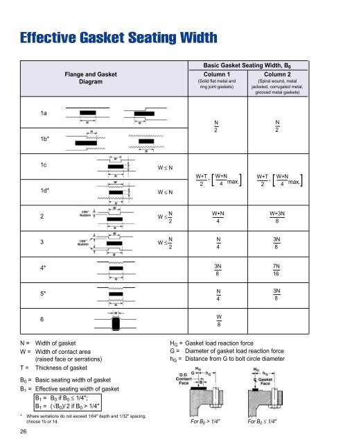
Effective Gasket Seating WidthBasic Gasket Seating Width, B 0Flange and Gasket Column 1 Column 2Diagram (Solid flat metal and (Spiral wound, metalring joint gaskets) jacketed, corrugated metal,grooved metal gaskets)1a1b*N2.N2.1c1d*W ≤ NW ≤ NW+T2, W+NW+T[ 4 max.],2W+N[ 4 max.]2W ≤ N 2W+N4W+3N83W ≤ N 2N4.3N8...4*3N8...7N16.5*N4.3N8...6W8.N =W =T =Width of gasketWidth of contact area(raised face or serrations)Thickness of gasketH G = Gasket load reaction forceG = Diameter of gasket load reaction forceh G = Distance from G to bolt circle diameterB 0 = Basic seating width of gasketB 1 = Effective seating width of gasketB 1 = B 0 if B 0 ≤ 1/4";B 1 = (√B 0 )/ 2 if B 0 > 1/4"* Where serrations do not exceed 1/64" depth and 1/32" spacing,choose 1b or 1d.26For B 0 > 1/4" For B 0 ≤ 1/4"
Gasket Factors "M" and "Y""M" and "Y" data are to be used for flange designsonly as specified in the ASME Boiler and PressureVessel Code Division 1, Section VIII, Appendix 2. Theyare not meant to be used as gasket seating stressvalues in actual service. Our bolt torque tables givethat information and should be used as such."M" - Maintenance FactorA factor that provides the additional preloadneeded in the flange fasteners to maintain the compressiveload on a gasket after internal pressure isapplied to a joint.M = (W - A 2 P) / A 1 PWhere: W = Total Fastener force (Ib. or N)A 2 = Inside area of gasket (in. 2 or mm 2 )P = Test pressure (psig or N/mm 2 )A 1 = Gasket area (in. 2 or mm 2 )"Y" - Minimum Design Seating StressThe minimum compressive stress in pounds persquare inch (or bar) on the contact area of the gasketthat is required to provide a seal at an internal pressureof 2 psig (0.14 bar).Y = W / A 1Gasket Min. DesignGasket Design Gasket Material Factor Seating Stress"M" "Y" (psi)Spiral wound metal,non-asbestos filledStainless steel or MONEL ® 3.00 10,000Garlock CONTROLLEDDENSITY ® flexible graphite- Stainless steel or MONEL ® 3.00 7,500filled spiral woundGarlock EDGE ® Stainless steel or MONEL ® 2.00 5,000Corrugated metal, Soft aluminum 2.50 2,900non-asbestos Soft copper or brass 2.75 3,700or Iron or soft steel 3.00 4,500Corrugated metal-jacketed, MONEL ® or 4%-6% chrome 3.25 5,500non-asbestos filled Stainless steel 3.50 6,500Soft aluminum 2.75 3,700Soft copper or brass 3.00 4,500Corrugated metal Iron or soft steel 3.25 5,500MONEL ® or 4%-6% chrome 3.50 6,500Stainless steel 3.75 7,600Soft aluminum 3.25 5,500Soft copper or brass 3.50 6,500Flat metal-jacketed, Iron or soft steel 3.75 7,600non-asbestos filled MONEL ® 3.50 8,0004%-6% chrome 3.75 9,000Stainless steel 3.75 9,000Soft aluminum 3.25 5,500Soft copper or brass 3.50 6,500Grooved metal Iron or soft steel 3.75 7,600MONEL ® or 4%-6% chrome 3.75 9,000Stainless steel 4.25 10,100Soft aluminum 4.00 8,800Soft copper or brass 4.75 13,000Solid flat metal Iron or soft steel 5.50 18,000MONEL ® or 4%-6% chrome 6.00 21,800Stainless steel 6.50 26,000Iron or soft steel 5.50 18,000Ring joint MONEL ® or 4%-6% chrome 6.00 21,800Stainless steel 6.50 26,000This table lists many commonly used gasket materials and contact facings with suggesteddesign values of "M" and "Y" that generally have proven satisfactory in actual service whenusing effective gasket seating width B 1 described in the formula on page 26. The designvalues and other details given in this table are suggested only and are not mandatory.MONEL ® is a registered trademarkof International Nickel.27