Multi-Stage Centrifugal Compressors - Elliott Turbomachinery
Multi-Stage Centrifugal Compressors - Elliott Turbomachinery
Multi-Stage Centrifugal Compressors - Elliott Turbomachinery

Create successful ePaper yourself
Turn your PDF publications into a flip-book with our unique Google optimized e-Paper software.
<strong>Multi</strong>-<strong>Stage</strong> <strong>Centrifugal</strong> <strong>Compressors</strong>Reliably serving the energy industries
Evolutionary Designs Revolutionary ResultsA History of Innovation and SuccessSince 1910, <strong>Elliott</strong> Company has earned a reputationfor providing innovative solutions, unmatched expertise,and first-class service to the global turbomachinerymarketplace. <strong>Elliott</strong> has designed, tested, and installedsome of the industry’s most rugged and dependableequipment. In fact, some <strong>Elliott</strong> compressors and turbinesinstalled in the 1940s and 1950s are still in operationtoday, either as originally supplied or upgraded to handlenew process conditions or more stringent environmentalstandards.We have been on the cutting edge of technologicaladvancement throughout our history, consistently providingadvanced technology in aerodynamics, rotor dynamics,process simulation, and metallurgy. Our customers havebenefited from our state‐of‐the‐art production innovations,including fabricated casing technology, high-pressurecasing technology, and impeller welding techniques. The<strong>Elliott</strong> EDGE TM development program evolved from ourcommitment to providing new approaches, processes, andtechnology while maintaining the quality and reliability thatour customers have come to expect.We understand that change is essential in achievingand maintaining a competitive edge in today’s businessenvironment. Together with our customers and suppliers,we continue to innovate, improve, and expand ourextensive portfolio of products and services that serve theenergy industries.Product Lines• Single/<strong>Multi</strong>-<strong>Stage</strong> <strong>Centrifugal</strong> <strong>Compressors</strong> (API 617)• Axial Air <strong>Compressors</strong> (API 617)• Single/<strong>Multi</strong>-<strong>Stage</strong> Steam Turbines (API 611)• <strong>Multi</strong>-<strong>Stage</strong> Steam Turbines (API 612)Applications• Oil Refineries• FCC Applications• Chemical/Petrochemical Plants• Ethylene Plants• Gas Lift/Gas Gathering• Gas Injection/Transport• LNG Facilities• Gas to Liquids• Ammonia Plants• Power Generation2
Advanced TechnologySuperior Performance Through AdvancedTechnologyThrough our EDGE development program, we combineour comprehensive knowledge of turbomachinery withthe latest design software, manufacturing processes, andmachine tools. As a result, <strong>Elliott</strong>’s multi-stage centrifugalcompressors lead the industry in both performance andreliability.Increased Aerodynamic Efficiency<strong>Elliott</strong> uses state-of-the-art interactive design and predictiontools to optimize aerodynamic performance and increaseflange-to-flange efficiencies. Compressor impeller andmatched stationary flowpath components are developedusing Computational Fluid Dynamics (CFD) analysesand other current design tools. Three-dimensional bladeprofiles, diffuser flow angles, crossover bend curvature,area ratio, and return channel vane shapes are optimizedfor each impeller stage to provide the best possibleefficiency. Additional performance enhancements areachieved by improving the flow distribution channels at theinlet and discharge volutes and sidestream mixing areas.These enhancements allow us to provide some of theindustry’s highest operational efficiencies.Improved Rotor Stability CharacteristicsThrough extensive research in the fields of rotor‐dynamicstability, aerodynamic cross-coupling stiffness, and rotorbearingsystems, we have developed proprietary analyticaltools. Incorporating these developments into <strong>Elliott</strong>compressor designs has produced a number of productenhancements. For example, we’ve increased rotorstiffness by increasing shaft diameter, reducing impellerweight, and increasing journal bearing sizes. This allowshigher torque transmission capabilities and higher‐speedoperation, with improved rotor stability characteristics,which are essential as gas densities and operatingpressures increase.3
Casing FeaturesWe Perform Under Pressure and Make Field Assembly Easier<strong>Elliott</strong> designed our EDGE compressor casings to reducethe required manufacturing steps and simplify fieldassembly. To achieve higher operating pressures, weapplied state-of-the-art solids modeling and finite elementanalysis techniques.Small and mid-sized horizontally split casing sections aremade from a single piece of rolled steel plate withhorizontal flanges that are machined—not welded—into theside. Cast steel casings are used for some applications.High-strength casing through-bolts provide superiorclamping forces. Endwalls are made from a single solidplate. The resulting casing has fewer sealing surfaces, iseasier to manufacture and assemble, and has increasedpressure capabilities compared to conventional designs.Larger horizontally split casings have rolled barrel sectionswith welded-on endplates and welded-on horizontalflanges.Vertically split MB-line compressors feature a completeinner casing assembly. This includes a horizontally splitinner casing with diaphragms, stationary seals, rotatingelements, bolted-on endwalls, and shaft end seals.This module can be inserted or removed from the outercasing as a single piece, which simplifies compressorassembly and reduces turn-around times.We typically use milled flats for SAE flanged connections,including endwall, spray nozzle, casing drain, bearingretainer, and equalizing line connections. On smallercasings where space is limited, SAE flanges provide higherratings and more compact designs than ANSI flanges.EDGE Casing Advantages• Integral horizontal flanges on small and medium frames• Solid endwalls with machined flats for bearing and sealconnections• Machined flats with SAE flanges for most drain orinjection connections• Through-bolts for casing horizontal flanges• Allowable forces and moments per API 617• Three-dimensional solid modeling for improved designand engineering review capability• Pro/ENGINEER solid modeling files to enhance precisionduring component manufacture4
Aerodynamic ComponentsAdvanced Aerodynamics and Enhanced Performance Give Our Customers the EDGEA key achievement of the EDGE development programis our ability to offer superior, three-dimensional impellerdesigns and stationary diaphragms. We do this bymaximizing performance over a broad range of pressureand flow applications using the latest aerodynamic designand analysis technologies. To verify predicted performance,single-stage testing is performed in various configurations,such as with vaneless or vaned diffusers, or using highor low tip Mach numbers. Higher and lower flow stageratings are derived from the prototype test data to forma “family” of stages. Within each stage family, impellergeometry is fixed; blade heights are varied for higher orlower flows. Using this methodology, several stage familiesare used to span the desired flow coefficient range.Impellers and stationary components are then scaled upor down for different frame sizes. For maximum flexibility,EDGE aerodynamic components are also scalable from90 percent to 100 percent size within each compressorframe size.EDGE compressors use either fabricated steel diaphragmsor a combination cast-and-fabricated steel design wherethickness precludes using steel plate alone. Precisionmachining ensures dimensional accuracy and significantlyimproves the diaphragm surface finish. Diaphragms arehorizontally split and finished at all horizontal and peripheraljoints and on gas path surfaces.Impeller manufacturing applies five-axis milling to ensurethe quality of the advanced impeller designs. Impellersare stress relieved, machine finished, balanced staticallyand dynamically, spin tested, and then mounted with aninterference-fit onto the shaft. Shaft-to-impeller keysare used for extra stability in high pressure orhigh power applications.5
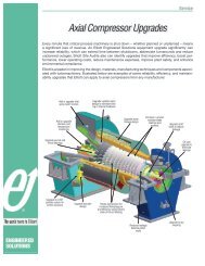
Proven TurbomachCast nozzles reduce manufacture timeand allow higher ratingsElimination of dished headsincreases pressure ratingsIncreased journal bearingand shaft seal sizesNon-radial inlet guide vanesimprove flow distribution6
inery TechnologyIncreased shaft diameterenhances rotor dynamicsPrecisely designed andmachined diaphragmsCFD ensures propersidestream mixingHigh-efficiency impellers scaleframe-to-frame7
Other FeaturesWe’ve Paid Careful Attentionto Every DetailAs part of our comprehensive EDGE development program,<strong>Elliott</strong>’s engineers examined each compressor componentto find ways to support our goals of higher efficiency, lowercost, simpler maintenance, and reduced cycle time. Ourdesigns reflect our commitment to making our products thebest in the industry, down to the last detail.Interstage and balance piston sealing is accomplishedthrough two component features. First, we use abradableor deflection-tolerant materials such as fluorosint ornickel-graphite on stationary sealing surfaces. Second,we machine teeth onto the rotating surfaces. Thesefeatures increase efficiency by reducing gas recirculationand minimizing the potential for shut‐downs resulting fromdamaged seals.<strong>Elliott</strong> offers shaft seals to meet our customers’ needs in allapplications. Dry gas seals are standard and are availableas single, tandem, double, or triple designs. The tandemor triple gas seal designs include an intermediate labyrinth,which can be buffered for additional emissions protection.Our customers realize cost savings by eliminatingexpensive seal oil systems and the need to dispose ofcontaminated oil. Gas seal buffer system engineeringand manufacturing are available at <strong>Elliott</strong>’s Donora,Pennsylvania, plant.Alternative seal designs include labyrinth or dry carbon ringseals for low pressure services, mechanical contact seals(<strong>Elliott</strong>’s patented Iso-carbon TM design), and bushing seals(<strong>Elliott</strong>’s Iso-sleeve TM design). For mechanical contact andbushing seals, a cartridge design is also available. Thisenables easier installation and removal of the completeseal assembly. Buffer connections are standard for all sealdesigns.Reliability, quality, and safety are hallmarks of all <strong>Elliott</strong>designedcomponents. For example, as a design standard,replaceable journal bearings are steel-backed and babbittlinedwith a five-shoe tilting pad. Thrust bearings aredouble-acting and self‐equalizing. Center pivots typicallyare used to make assembly easier and to provide maximumprotection if reverse rotation occurs. Chrome-copper padsare applied for both journal and thrust bearings for high oiltemperature applications.8
Manufacturing and Testing CapabilitiesA Commitment to World‐Class Manufacturing<strong>Elliott</strong> employs high-quality production techniquesthat minimize cycle time and costs while providing ourcustomers with the most competitive and reliable products.Our engineering and manufacturing facilities in Jeannette,Pennsylvania, and Sodegaura, Japan, rank among theworld’s most advanced for turbomachinery design,production, and testing.Our combined manufacturing capabilities includeMasterhead machining centers for casing machining, rotormachining centers, and diaphragm machining centers. Ourrotor balancing facilities include a state‐of‐the‐art SchenckTrebel‐designed balancing machine housed in a bunkerstylevacuum chamber. The top of this reinforced concretefacility slides away via hydraulic motors, permitting rotors tobe lowered onto the balancing equipment.Our recently modernized and expanded test facilitiesenable us to validate the mechanical integrity andperformance of our components and overall systems.Our new main test facility, which increased our capacityby 50 percent, contains a high‐volume, closed loop,specially designed cooling system with the capacity fortesting gas turbine-driven compressor trains at full loads upto 100,000 HP.Masterhead casing centerDiaphragm machining cellHigh-speed balance facility9
Compressor Frame SummariesFrameTypical Flow Range(icfm)(m 3 /h)Casing RatingAxial Split(psig) (Barg)Casing RatingRadial Splite(psig) (Barg)10M1,000 68.95 — —1,700 - 5,400 2,900 - 9,20010MB — — 10,000 689.4815M1,000 68.952,200 - 7,100 3,700 - 12,10015MB — — 10,000 689.4820M1,000 68.95 — —2,900 - 9,400 4,900 - 16,00020MB — — 10,000 689.4825M1,000 68.95 — —3,900 - 12,500 6,600 - 21,20025MB — — 10,000 689.4829M1,000 68.95 — —5,100 - 16,500 8,700 - 28,00029MB — — 10,000 689.4832M1,000 68.95 — —6,800 - 21,800 11,500 - 37,00032MB — — 5,000 344.7438M1,000 68.95 — —9,000 - 28,800 15,300 - 48,90038MB — — 3,000 206.8446M1,000 68.95 — —11,900 - 38,100 20,200 - 64,70046MB — — 2,000 137.9056M1,000 68.95 — —15,700 - 50,400 26,700 - 85,60056MB — — 2,000 137.9060M1,000 68.95 — —20,800 - 67,000 35,300 - 113,80060MB — — 2,000 137.9070M750 51.71 — —27,500 - 88,000 46,700 - 149,50070MB — — 1,500 103.4278M600 41.37 — —36,400 - 117,000 61,800 - 198,80078MB — — 1,500 103.4288M600 41.37 — —48,100 - 154,000 81,700 - 261,60088MB — — 1,000 68.95Nominal ImpellerDiameter(in.) (mm)NominalSpeed(rpm)10.38 263.55 19,80011.93 303.07 17,30013.72 348.54 15,00015.78 400.81 13,10018.15 460.93 11,40020.87 530.10 9,90024.00 609.60 8,60027.60 701.04 7,50031.74 806.20 6,50036.50 927.13 5,60041.98 1,066.19 4,90048.27 1,226.13 4,30055.51 1,410.03 3,700103M 63,600 - 203,000 108,100 - 344,900 400 27.58 N.A. 63.84 1,621.54 3,200110M 84,100 - 270,000 142,900 - 458,700 400 27.58 N.A. 73.42 1,864.79 2,800Standardization of ComponentsIn developing the EDGE compressor product line,we focused on standardizing components and hardwareto reduce costs and improve reliability across a widearray of applications. The EDGE product line consistsof 15 standard frame sizes, which are scaled from the38M median frame size. Casing bores and internalaerodynamic hardware, such as impellers, diaphragms,and shafts, are scaled. Scaling aerodynamic componentsimproves performance predictability and increasesreliability by preserving geometric similarity across framesizes. Bearings and seals are selected from vendorstandard sizes for each application.10
Weights, Dimensions and ConfigurationsFrameSizeMinimumRotor Length(in. / mm)MaximumRotorLength(in. / mm)Casing Width(includessupports)(in. / mm)Casing Height(exc. supports)(in. / mm)Minimum CasingWeight(lb/kg)Typical Weights and Dimensions for <strong>Elliott</strong> Horizontal Split <strong>Compressors</strong>*Maximum CasingWeight(lb / kg)10M 35 / 890 64 / 1,625 37.3 / 947.4 36.25 / 921 4,700 / 2,130 9,000 / 4,08015M 35 / 890 75 / 1,905 42.5 / 1,080 41.38 / 1,051 5,600 / 2,540 12,700 / 5,760In-Line20M 40 / 1,015 80 / 2,030 48.5 / 1,232 47.85 / 1,215 8,200 / 3,720 18,000 / 8,16525M 45 / 1,145 90 / 2,285 55.1 / 1,400 54.12 / 1,375 11,100 / 5,035 24,500 / 11,10029M 50 / 1,270 110 / 2,795 65.4 / 1,661 59.25 / 1,505 14,000 / 6,350 32,000 / 14,50032M 50 / 1,270 124 / 3,150 70.5 / 1,791 65.75 / 1,670 15,700 / 7,120 45,000 / 20,40038M 55 / 1,400 135 / 3,430 76.3 / 1,938 70.62 / 1,794 23,000 / 10,430 62,000 / 28,10046M 70 / 1,780 155 / 3,940 66.5 / 1,689 89.5 / 2,273 32,500 / 14,740 87,000 / 39,500In-Linewith Side-Streams56M 80 / 2,032 175 / 4,445 76 / 1,930 93.38 / 2,372 51,500 / 23,360 127,000 / 57,60060M 90 / 2,285 190 / 4,825 89.7 / 2,278 97 / 2,464 59,000 / 26,760 170,000 / 77,10070M 100 / 2,540 230 / 5,840 103.5 / 2,629 113.88 / 2,893 71,000 / 34,000 210,000 / 95,25078M 100 / 2,540 250 / 6,350 109.5 / 2,781 125.5 / 3,188 95,000 / 43,100 295,000 / 133,80088M 115 / 2,920 275 / 6,985 133 / 3,378 137.5 / 3,492 130,000 / 59,000 380,000 / 172,400103M 135 / 3,429 300 / 7,620 156 / 3,962 158.5 / 4,025 215,000 / 97,500 525,000 / 238,100110M 140 / 3,556 325 / 8,255 182 / 4,623 182 / 4,630 270,000 / 122,470 690,000 / 312,980In-Linewith Iso-CoolingTypical Weights and Dimensions for <strong>Elliott</strong> Vertical Split <strong>Compressors</strong>*10MB 35 / 890 62 / 1,575 43 / 1,092 42.5 / 1,080 7,000 / 3,175 13,000 / 5,90015MB 35 / 890 72 / 1,830 46 / 1,168 48 / 1,219 8,400 / 3,810 17,500 / 7,94020MB 40 / 1,015 80 / 2,030 50 / 1,270 53.75 / 1,366 12,000 / 5,440 25,000 / 11,34025MB 45 / 1,145 88 / 2,235 58.5 / 1,486 62 / 1,575 18,400 / 8,345 36,000 / 163,03029MB 50 / 1,270 105 / 2,670 64.3 / 1,633 64 / 1,626 23,000 / 10,435 49,000 / 22,225Double-Flow32MB 50 / 1,270 120 / 3,050 71.7 / 1,821 76.5 / 1,943 28,500 / 12,900 69,000 / 31,30038MB 55 / 1,400 130 / 3,300 78.5 / 1,994 83.25 / 2,115 36,500 / 16,560 89,000 / 40,40046MB 70 / 1,780 150 / 3,810 96.5 / 2,451 86.5 / 2,197 47,500 / 21,500 115,000 / 52,20056MB 80 / 2,030 170 / 4,320 104.2 / 2,647 102.12 / 2,594 70,000 / 31,750 160,000 / 72,60060MB 90 / 1,525 185 / 4,700 113 / 2,870 112.5 / 2,858 90,000 / 41,000 200,000 / 91,00070MB 100 / 2,540 225 / 5,715 115.2 / 2,926 120.96 / 3,064 100,000 / 45,350 251,000 / 113,90078MB 100 / 2,540 245 / 6,225 120 / 3,048 140 / 3,556 125,000 / 56,700 315,000 / 143,000Back-to-BackIso-Cooler Optional88MB 115 / 2,920 265 / 6,730 137 / 3,480 148 / 3,759 205,000 / 93,000 465,000 / 211,000*All data are estimates.11
www.elliott-turbo.com<strong>Elliott</strong> Group901 North Fourth StreetJeannette, PA 15644-1473Phone: 724-527-2811Fax: 724-600-8442Email: info@elliott-turbo.com<strong>Elliott</strong> Company reserves the right to modify the design or construction of theequipment described in this bulletin and to furnish it, as altered, without furtherreference to the illustrations or information contained herein.©<strong>Elliott</strong> Group 2010