Finite Element Analysis (FEA) - Directories
Finite Element Analysis (FEA) - Directories
Finite Element Analysis (FEA) - Directories
- No tags were found...

You also want an ePaper? Increase the reach of your titles
YUMPU automatically turns print PDFs into web optimized ePapers that Google loves.
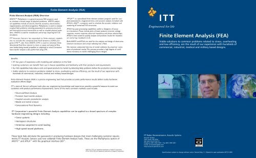
<strong>Finite</strong> <strong>Element</strong> <strong>Analysis</strong> (<strong>FEA</strong>)<strong>Finite</strong> <strong>Element</strong> <strong>Analysis</strong> (<strong>FEA</strong>) OverviewANSYS Multiphysics is a general purpose <strong>FEA</strong> program usedto simulate a broad range of physical problems. ANSYS analyticalcapabilities include structural, thermal, acoustics, electrostatics,magnetostatics, and electromagnetics. Multiphysics is used to analyzecoupled field problems including piezoelectrics, pressure-structuraland thermal-structural interactions as well as coupled physical problems.ANSYS is used for transducers and arrays requiring full 3-Dsimulation.ITT Acoustic Sensors has expanded its finite element capabilitiesto include the computational fluid dynamics (CFD) programCFX, also from ANSYS. CFX is used to simulate threedimensionalfluid flow internal to ducts or pipes and external flowover bodies being towed, propelled, or subjected to wind. Convectiveheat transfer analysis is also performed using CFX.ATILA is a specialized finite element analysis program used for coupledpiezoelectric, magnetostrictive, and acoustic analysis. Included withATILA is EQI, a program used to simulate the acoustic radiation andscattering of immersed 3-D structures.ATILA has post-processing capabilities useful to designers of acoustictransducers. These include plots of beam patterns, transmit voltageresponse, receive response, electrical impedance and phase relationships.ATILA is best suited to quickly analyze and produce results for transducersand arrays modeled in 2-D.Both ANSYS and ATILA are used for the analysis and design of electromechanicaltransducers and arrays radiating into a fluid.We maintain substantial histories of model validation by empirical evaluationof predicted results. This process provides a high degree of confidencenecessary to tackle challenging future designs.<strong>Finite</strong> <strong>Element</strong> <strong>Analysis</strong> (<strong>FEA</strong>)Viable solutions to common problems related to stress, overheatingand low efficiency, are the result of our experience with hundreds ofcommercial, industrial, medical and military based designs.Benefits• ITT has years of experience with modeling and validation in the field• Existing customers can benefit from our in-house capabilities and familiarity with their products and requirements• Our <strong>FEA</strong> capabilities help reduce costs and speed products to market by detecting likely problems before the production process begins• Viable solutions to common problems related to stress, overheating and low efficiency, are the result of our experience withhundreds of commercial, industrial, medical and military based designs<strong>Finite</strong> <strong>Element</strong> <strong>Analysis</strong> (<strong>FEA</strong>) is a precise engineering tool that provides accurate performance results before costly hardwareevaluation efforts begin.ITT’s state-of the-art software tools plus our engineering knowledge and experience provide a powerful resource to assist ourcustomers with product performance improvements. Some of the more common methods used include:• Structural/Shock <strong>Analysis</strong>• Transient heat transfer analysis• Coupled acoustic piezoelectric analysis• Modal and inertial analysis• Computational Fluid DynamicsITT Corporation’s powerful <strong>Finite</strong> <strong>Element</strong> <strong>Analysis</strong> capabilities can be applied to a broad spectrum of complexhardware engineering designs including:• Sonar systems• Aerospace structures• Antennas subjected to wind loading• High speed towed platformsThese tools help eliminate the guesswork in producing hardware designs that meet challenging customer requirements.ITTAcoustic Sensors uses two validated <strong>Finite</strong> <strong>Element</strong> <strong>Analysis</strong> tools. These are the Multiphysics option ofANSYS and ATILA with the graphical interface GID.ANSYS & CFX are registered trademarks of ANSYS Corporation.ATILA, GID & EQI are registered trademarks of Magsoft Corporation.ITT Radar, Reconnaissance, Acoustic SystemsAcoustic System2645 South 300 WestSalt Lake City UT 84115Telephone (801) 486-7481 • Fax (801) 484-3301E-mail: as-marketing@itt.comhttp://acousticsystems.itt.comSpecifications subject to change without notice. Revised May 11. Cleared for open publication #07-S-1659
<strong>Finite</strong> <strong>Element</strong> <strong>Analysis</strong> (<strong>FEA</strong>)These illustrations detail threeof the ways we have appliedour <strong>Finite</strong> <strong>Element</strong> <strong>Analysis</strong>capabilities to assist our customersin finding the mostefficient way to meet dynamicperformance requirementsusing piezoelectric basedtransducer technology.Predicted Thermal Response- Transient heat transfer analysisof a high voltage poweroperational amplifier subjectedto repetitive power dissipationcycling3D Modeling and analysisallowed ITT to predict thermalresponse and provide the benefitof improved cooling.Nodal SolutionTIME = 11.568TEMP (AVG)RSYS = 0SMN = 24.024SMX = 52.81324.02427.173 30.322 36.61933.471 39.768 42.917 46.06649.21552.813Nodal SolutionTIME = 11.566TEMP (AVG)RSYS = 0SMN = 43.511SMX = 88.68543.51148.45253.39358.333 53.274 68.215 73.156 78.09783.038 88.685Half symmetry 3D finite element model.Two power amplifiers with common heatsinkand cylinder enclosure in waterPeak temperature contour forpower amplifiers with heatsinkand cylinder in waterPeak temperature contour forpower amplifiers only in airThermal response in air without heatsinkand with heatsink in water showsimproved coolingStructural Shock <strong>Analysis</strong> - Modaland inertial analysis simulatingshipboard shock loading of a towbody frame for a flextentionaltransducer array.<strong>Analysis</strong> of the frame allowed ITTto confirm that the frame designwould withstand shipboard shock.FlextensionalTransducerStrong BackMounting PointFrameForwardSectionCable Support RodFrame AftSectionFrame AftMiddle SectionFrame ForwardMiddle Sectionzyx0zNodal SolutionStep = 1SUB = 1FREQ = 12USUM (AVG)RSYS = 0DMX = .132127SMX = .132127yx.029362 .058723 .088085 .117447.014681 .044042 .073404 .102766 .132127Nodal SolutionStep = 1SUB = 1TIME = 1SEQV (AVG)DMX = .269E-03SMN = 978.729SMX = .912E+07RFOR978.729 .203E+07 .406E+07 .608E+07 .811E+07.101E+07 .304E+07 .507E+07 .710E+07 .912E+073D solid model of an array frameFull 3D <strong>FEA</strong> model of the towbody frame including essentialstructural featuresShape of lowest frequency modein the longitudinal directionReaction moments and forces atbolted connections to the frameVon-Mises stress distribution for highstress region of frame subjected to longitudinalinertial loadingTonpilz Transducer Design -ITT used ATILA modeling to predictactive mode shapes, transmitvoltage response vs frequency, anddynamic stresses.This capability helped designers tomeet performance requirements fora Tonpilz transducer.AluminumHead MassSteelStressRodCeramic Stack6 EC-64 <strong>Element</strong>sTungstenTail MassSyntacticFoamSupportyzxDeformation (x40000): Mode Shape of Resonance Modes, Step 2yzWATERSTEEL3ALUMINUM3TUNGSTEN2SYNTACTIC FOAMTG-24EPDMEC-64xyz– 149.99– 43.258– 63.441– 170.14– 276.84– 383.54– 490.24– 596.94– 703.64– 810.33x3D solid model of thetransducer using 2 planesymmetryCross section of the transducer modelfor Active Mode #2Model illustrating materials usedin the transducer assembly2D pressure field showingmagnitude and attenuationPredicted performance agreeswell with empirical results