
You also want an ePaper? Increase the reach of your titles
YUMPU automatically turns print PDFs into web optimized ePapers that Google loves.
<strong>Hypex</strong> Electronics BVKattegat 89723 JP Groningen, The Netherlands+31 50 526 4993info@hypex.nlUser Manual<strong>AS2.100</strong><strong>Hypex</strong> AS2 - Series
User manual revision 5<strong>AS2.100</strong>Table of contentsProduct description.................................................................................................................................. 3Type remarks ........................................................................................................................................ 3Key features .......................................................................................................................................... 3Applications........................................................................................................................................... 4Connections........................................................................................................................................... 5System information................................................................................................................................. 7Description ............................................................................................................................................ 7Hardware Architecture......................................................................................................................... 8Digital audio input................................................................................................................................ 8Audio performance data...................................................................................................................... 8Remote control ..................................................................................................................................... 9Product overview ...................................................................................................................................... 9Hardware part .....................................................................................................................................10Sub-out.............................................................................................................................................12Linking ..............................................................................................................................................12Software installation..........................................................................................................................13Control panel.......................................................................................................................................13Input options.......................................................................................................................................14Filter design.........................................................................................................................................15Graph Area...........................................................................................................................................16Filter Definition Area..........................................................................................................................16Settings window..................................................................................................................................17Work flow.............................................................................................................................................17Measurement...................................................................................................................................17Designing filters ..............................................................................................................................20Download.............................................................................................................................................21Save Files .............................................................................................................................................21Firmware update.....................................................................................................................................21Examples..................................................................................................................................................23Example 1: 2-channel stereo setup..................................................................................................23Example 2: Stereo setup with active subwoofer.............................................................................25Technical data.........................................................................................................................................27- 2 -
User manual revision 5<strong>AS2.100</strong>Product descriptionType remarks- The first time the <strong>AS2.100</strong> is used all biquads are zero, so there are nofilters installed. Connecting any speakers and audio input at this pointmay cause some damage to them.- Take notice on what changes you make, changing a 2channel filters to flatcan damage your speakers because both channels may be full range!- After updating the firmware please be sure to also download the latestversion of the manual from our websiteFirmware version 2.4 (Oct 2011)Key featuresCompact designPersonal Computer controlledTwo UcD180LP OEM power amplifiersPop-free start and stop controlStereo analogue inputSubwoofer outputFully user customised filteringButton panel controlledRemote controlledLink communication master / slave (only with two modules)Low signal to noise (-100dB)Optional features, by adding a digital audio board.SPDIF stereo audio inputInput sample rates up to 192kHzLink communication trough SPDIF link cable (one cable for audio and link)USB audio inputLow signal to noise (-104dB)- 3 -
User manual revision 5<strong>AS2.100</strong>ApplicationsWith one module the following applications can be set up, further explained in the “Hardwarepart” chapter:Stereo passive filtered systemBriged mode for single subwoofer (max 140Watt short term into 8 Ohms)Mono/mid 2-way setup (tweeter + sub)When two modules are used the following applications can be set up, also explained in“Hardware part”:2-way active filtered stereo system2 channel system with active subwoofer2 channel system, both modules in bridge mode for more powerAll setups are possible with both analogue and optional with the digital audio inputs SPDIF andUSB.Note that all setups have the ability to use an extra channel by connecting an active subwooferto the subout. By this you will have the opportunity to build a 3-way system.- 4 -
User manual revision 5<strong>AS2.100</strong>ConnectionsFigure 1Overview of the connections on the front of the <strong>AS2.100</strong>.Function1 Amplifier output, for slave speaker in stereo setup4 Analogue input left channel5 Analogue input right channel6 Subwoofer output7 On/Off switch8aUSB control input- 5 -
User manual revision 5<strong>AS2.100</strong>9 Master trigger output, slave trigger inputRight channel trough10 Main Fuse11 ~230 volt inputDigital version only:2 SPDIF audio input3 SPDIF audio outputAudio trough for slave module8bUSB audio inputFigure 2Overview of the connections on the back of the <strong>AS2.100</strong>.Function1 Transformer connection2 JP1, Bridge jumper3 J4, Stereo=Left channel output2 channel=Low channelPin1 (left) = Speaker -Pin 2 (right) = Speaker +4 J2, Stereo=Right channel output2 channel=High channelPin1 (left) = Speaker -Pin 2 (right) = Speaker +5 J3, Connection of banana plugsPhysically the same as connector J26 Transformer connection7 Control panel flat-cable connector- 6 -
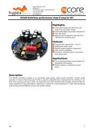
User manual revision 5<strong>AS2.100</strong>System informationDescriptionFigure 3The “<strong>AS2.100</strong>” is a plate amp for use in powered speaker systems. As an active speakercontroller, a <strong>AS2.100</strong> can form the basis of a powerful active two-way monitor. In stereo modeone <strong>AS2.100</strong> will power an active master / passive slave pair. Finally, the module may also beused as a one-way 140W amplifier. All signal processing, including volume control, is doneusing the on-board DSP (digital signal processor).Figure 3 shows the block diagram of the amplifier. When two modules are used, the second unitslaves to the first unit (master) through a link cable. The link cable (a stereo mini jack cable)carries both the right audio channel and control data. This way, both units respond to themaster’s control panel.A PC controls the <strong>AS2.100</strong> through the USB port. This connection is used to upload theconfiguration and filter settings. An optional board permits use of the USB link for audio as wellas an SPDIF link. In digital mode, master/slave linking is done through the SPDIF in/outconnections instead of the mini jack cable.- 7 -
User manual revision 5<strong>AS2.100</strong>Hardware ArchitectureThe standard version of the <strong>AS2.100</strong> has a stereo analogue audio input. This analogue signal isconverted to digital, processed by the DSP and then converted back to analogue. Amicrocontroller controls the DSP, reads the control panel and communicates with the PCand/or another <strong>AS2.100</strong> that may be attached.Digital audio inputThe optional digital input board plugs into the main PCB and carries two RCA connectors, SPDIFin and SPDIF through. Incoming SPDIF is linked through directly to the output and sent to theDSP through an asynchronous sample rate converter (ASRC) for jitter removal. The USB partadds a hub and an audio device which in turn also transmits audio over the ASRC to the DSP.The ASRC chip scans its input for whichever signal is active. In a stereo setup and in digitalmode the SPDIF through cable doubles as a master/slave link, obviating the need for the minijack cable. The mini jack cable remains functional though and does not have to be removed.Audio performance dataMBW=20kHz, unless otherwise noted. All filters set to unity. Noise levels unweighted.Item Symbol Min Typ Max Unit NotesInput level Vin 2.2 VInput impedance 10k Ohm Analogue cinch inputsOutput levelLS1 100* W Into 4 OhmsLS2 100* W Into 4 OhmsLS1 50 W Into 8 OhmsLS2 50 W Into 8 OhmsSignal/NoiseSNR100 dB ADC104 dB DACTotalharmonic THD+N 0.05 0.07 % UcD180LP specsdistortion+Noise20Hz
User manual revision 5<strong>AS2.100</strong>Remote controlThe master unit is fitted with small keypad which can be placed in the front of the loudspeakercabinet. Volume and idle/on is controlled by the pushbuttons and by an infra red remotecontrol. When 2 <strong>AS2.100</strong> modules are used only one control panel is needed, cause the triggercommunication between master and slave.There is also a touch panel available at www.hypexshop.com. This can replace the standardcontrol panel.The use of an Inferred remote control adds the ability to switch input channels with the up anddown buttons of the remote. The <strong>AS2.100</strong> uses a standard RC-5 TV protocol for Infraredcontrol.Product overviewBefore you can use the <strong>AS2.100</strong> in your particular setup, you first have to set the rightsettings. This is done by pc software, called <strong>Hypex</strong> DSP filter design.Please do not connect any speakers to your system yet!When you want to set up a system with the <strong>AS2.100</strong> you apparently know what you want. Sowith this information you can setup your system as follows:- Stereo setup, in this setup you use one <strong>AS2.100</strong> module for driving two(passive filtered) speakers.- Bridged setup, the possibility to bridge both amplifiers on the AS2 willenable you to get more power at higher loads. This setup is especially usefulfor driving a subwoofer- 2-channel setup. A 2-channel setup will allow you to make a two-way activespeaker. Each amplifier of the <strong>AS2.100</strong> will drive one driver of the speaker,i.e. high, mid or low. In this setup you will need one <strong>AS2.100</strong> per speaker.- A combination of the above mentioned setups is also possible, for example astereo setup with an active subwoofer with an <strong>AS2.100</strong> in bridge mode, seeFigure 4.- 9 -
Volume UpVolumeDownLedOn/OffPC amp V1.0Ir RecieverUser manual revision 5<strong>AS2.100</strong>Figure 4Hardware partStereo setup:Connect the module to your pc by a USB cable and select on witch side of theroom your master module will be, the speaker with the <strong>AS2.100</strong>. When yourmaster is the left channel the slave will become the right channel. The slavespeaker can be connected by the banana-plugs on the <strong>AS2.100</strong>.Stereoaudio inControlPanelLeft speakerRight speakerFigure 5- 10 -
Volume UpVolumeDownLedOn/OffPC amp V1.0Ir RecieverUser manual revision 5<strong>AS2.100</strong>Bridged setup:Connect the module to your pc by a USB cable and select where the mastermodule is placed, master module is left or right audio or functions as asubwoofer. When you use 2 <strong>AS2.100</strong> for a stereo bridged setup you will alsohave to initialise the second (slave) module, see example in the last chapterof this document. In bridged mode the jumper (see Figure 2) must be placedand the speaker must be connected between J4 speaker+ and J2 speaker+. Inall other setups the jumper is not placed! When you want to set the masteras right channel with analogue input you will have to change the inputcinches, left in the right cinch and right in the left. This is because only theright channel is linked trough, so if you want the left channel to be linkedtrough you just switches left and right. For digital sources the left and rightchannel are linked.2 Channel: Connect the module to your pc by a USB cable and select what kind of 2channel you want to setup. When you want to set the master as rightchannel with analogue input you will have to change the input cinches, leftin the right cinch and right in the left. This is because only the right channelis linked trough, so if you want the left channel to be linked trough you justswitches left and right. For digital sources the left and right channel arelinked. An example is given in the last chapter of this document.Stereoaudio inControlPaneltrigger +right chLF HF LF HFFigure 6- 11 -
User manual revision 5<strong>AS2.100</strong>Sub-outOn all setups there is also the ability to use the Line out sub. This can source an activesubwoofer module. The sub output has up to 6 biquads for filtering that can exclude the use ofan external subwoofer filter.LinkingWhen 2 modules are used these two can be linked by a trigger cable. This cable holds devicedata and also carries an audio channel on analogue source. If the digital board is installed thenthe SPDIF link cable can be used to communicate between the 2 modules. This cable is placedfrom master SPDIF out to slave SPDIF in cinch. The trigger cable is no longer needed in thissetup. On USB audio input on the master the SPDIF output is also used for linking master toslave.- 12 -
User manual revision 5<strong>AS2.100</strong>Software installationSystem requirements:• Pentium class or higher• 64MB RAM• USB1.0 or higherTested on Windows XP and VistaAll files are compressed in the setup.zip file. This zip file contains a DLL file for communicationand a .EXE file, which represents the <strong>Hypex</strong> DSP filter design program.1. Unzip the setup.zip file on your hard disk2. Open the “<strong>Hypex</strong> DSP filter design.EXE” by double clicking the fileControl panelNow the program is ready for use. You seethe following window, called the controlpanel.Figure 7When the program is running connect your <strong>AS2.100</strong> to your pc by theUSB cable. Windows will automatically detect and install the AS 2.100and the USB audio device (digital version only). When the installationis done the connected window will appear and the connection light willturn green. You can also manually make a connection by the“connect” button, on the bottom right of the control panel.Figure 8Now you can adapt the settings of the <strong>AS2.100</strong> real time through USB. On the left of thecontrol panel you see the Force input and active input groups. This shows you the settings ofthe audio inputs of the <strong>AS2.100</strong>, and lets you control these inputs (only when digital audioboard is added).Audio can be provided in 3 ways, analogue, SPDIF and USB audio. The selection of any of theseinputs can be automatic, “auto detect”. This means that when any of the inputs is presentedthere will be switched to this channel automatically. This is done by setting the analogue input- 13 -
User manual revision 5<strong>AS2.100</strong>as the standard source. During analogue in the other two inputs are scanned for any validsignal. The first channel that contains any valid audio is selected and becomes the new inputsource. But if you put in the USB cable but you want to use the analogue input you can forcethe analogue input to be used. This can be done for all inputs, the options Analogue, SPDIF andUSB Audio.When the module selects one of the inputs this is shown by the active input lights.Under the Setup select part the system setup can be selected. There can be chosen between:2-channel Stereo BridgedMaster on the left Master on the left Master on the leftMaster on the right* Master on the right* Master on the right*Mid/Sub, L+RSub, L+RSide, L-R* Only on digital audio board, for analogue version cinches has to be changed like described in‘Hardware part’.The output signal of the subout channel is controlled in the “Subout control” panel. Normallythis will be set to L+R to use one subwoofer, but if you want to use a subwoofer on both sidesyou can set the subout to only use left or right input signal.The last thing that can be controlled in this window is volume. This can be done by setting thescrollbar to a desired position or by typing the value in the volume field, this value is send whenpressed “enter”.All of the configurations made here will be redirected from master to slave, when presented. Sothere is no need to connect the slave module to the pc.The slave module is always the opposite of the master, so master left will set the slave to right.This is done automatically because the module knows whether it is master or slave.Only when the module is switched off by remote all settings, like volume and setup, are storedin memory.Input optionsUse this dialog to match the input sensitivity of theanalogue input to the full-scale output level of youranalogue source (max. 2.2V). This helps preventannoying loudness jumps when switching betweendigital and analogue sources.Gain can be changed in steps of one dB and only for theanalogue input.Figure 9- 14 -
User manual revision 5<strong>AS2.100</strong>Filter designWhen you want to make some filters foryour module they can be designed inthe “Filter design”. Under view there canbe switched between the control paneland the filter design window.The following pages will give you awidespread instruction of thepossibilities of the program.Figure 10Figure 11- 15 -
User manual revision 5<strong>AS2.100</strong>Graph AreaThe magnitude tab shows the imported driver responses, filters, individual biquads, individualfiltered driver responses and the sum.ColourFunctionBlue, thinMeasured woofer responseGreen, thinMeasured midrange responseRed. thinMeasured tweeter responseBlue, thickFiltered woofer responseGreen, thick Filtered midrange responseRed, thickFiltered tweeter responseLight blue, thick Response of filter, selected channel onlyOrange, thick Response of selected biquadBlack, thick Sum responseHaving all of these on at the same time quickly produces an intractable mess so these graphscan be separately enabled or disabled in the filter definition area.The impulse or step tabs show the time domain response of the imported drivers and the sumresponse, and are used to demarcate the anechoic portion.Filter Definition AreaThe three channel tabs, labelled Tweeter, Woofer and Subwoofer are functionally identical. Thetop left frame is used to import response files. The “select” button opens a file. The “show”checkbox turns display of the measured graph on or off. The Common Settings box controlsglobal gain (for each channel), delay, and the visibility of plots.The amplified channels have up to 12 biquads, selected using the “Biquad Section” radiobuttons in the middle. The Subwoofer lineout has only 6 biquads sections, for only simple filtersettings. To the right is a settings area specific to the type of function selected. Unusedbiquads are set to unity.The selected biquad is edited by selecting a function and setting relevant parameters.The delay has a maximum value of 1000us for channel 1 and 2. The subwoofer channel doesnot include any delay. Distance is calculated by sound speed/delay=distance, maximumdistance is therefore 340,29meters/0,001secondes=34,029cm. Note that the minimum stepsizeis 0,726cm cause the sample rate of 46875Hz.The sample frequency is not the standard 48kHz because of internal clock source also neededfor USB connection.- 16 -
User manual revision 5<strong>AS2.100</strong>Settings windowThe settings window is under File > Settings… Measurement sampling rate sets the sample rateused in the imported response files (typically 48kHz). Processor sampling rate is that of the<strong>Hypex</strong> DSP hardware. Note that this setting does not control the sampling rate of thehardware. Rather, it informs the filter design application of what that sampling rate is. In short,leave this at the standard value.The select button opens a file dialogue box witch is not used in this application.Work flowMeasurementMeasuring using the DSP unit set to “flat”Perform impulse response measurements for each driver separately. Save the entire impulserecord – truncation can be done later on the filter design program.Measuring using an external amplifierA separate amplifier may also be used for measuring the drivers, provided the amplifier’soutput impedance is as low as the DSP unit’s.Importing response dataSelect the tab for the channel you want to import and click “select”. The filter designer expectsthe impulse response measurement as a text file with one sample per line.There is no restriction on the absolute gain of the impulse response data. The only thing thatmatters is that the absolute gain be the same for all three measurements. The filter designercomputes a gain offset based on all loaded responses to centre them collectively on the verticalscale.Truncating response dataSwitch to the impulse or step response graph.- 17 -
User manual revision 5<strong>AS2.100</strong>Figure 12The first echo is apparent at 5ms. Zoom in until you see only the anechoic portion of theimpulse response. Dragging the mouse, left-button down, from left to right marks a zoom area.Dragging from right to left zooms out. Dragging with the right button down pans the plot leftand right.- 18 -
User manual revision 5<strong>AS2.100</strong>Figure 13Click “truncate”. Anything currently outside the display is drawn in grey and not processed.You will notice that in the frequency graph a portion of the low-frequency response is alsodrawn in grey. This is to remind the user that insufficient information is available to make*any* correction below this frequency. A way of obtaining quasi anechoic low-frequencymeasurements is making close-up measurements. Working with such measurements requiresa good deal of interpretation but it is doable.Important: Avoid making any corrections for which no anechoic data is available. If reflectionsare included, they are guaranteed to dominate the measurement at low frequencies, and youwill end up making corrections for circumstances that are highly specific to the room in whichthe measurement was made. Power-response data can only be made in a proper echo chamberor preferably, by collating a large number of anechoic off-axis measurements. A reverberantmeasurement in a normal live room just won’t do.The steps of loading and truncating data can be repeated at any time. This can be particularlypractical when combining close-up and far-field measurements during the filter design phase.The window in Figure 13 shows the result of this. The small knot of corrections made around70Hz is based on close-up data first loaded separately. The LF section of the test mule is quitesmooth apart from one internal standing wave.- 19 -
User manual revision 5<strong>AS2.100</strong>Designing filtersBiquad function Parameters UseUnity - Section is not usedLPF1 Cut-off frequency (always -3dB) First order lowpassLPF2Cut-off frequency (asymptotically)QSecond order lowpass. A Q of 0.71corresponds to butterworth. 0.5corresponds to LR2. Two identicalsections with a Q of 0.71 form anLR4 filter.HPF1 Cut-off frequency (always -3dB) First order highpassHPF2Cut-off frequency (asymptotically)QSecond order highpass. A Q of 0.71corresponds to butterworth. 0.5corresponds to LR2. Two identicalsections with a Q of 0.71 form anLR4 filter.Shelf1Shelf2Asymmetric ShelfBoost/CutCentre Frequency (halfway point)GainDirectionCentre Frequency (halfway point)GainQDirectionPole frequency and QZero frequency and QCentre frequencyQgainFirst order shelf. Useful for bafflestepcorrectionSecond order shelf. Useful forcorrecting internal cabinetresonances and for the midbandpeak/dip combo of most midwooferspeakers.Equalising the bottom end ofclosed-box woofers with largemagnetsDip/peak filter. For peaks, Q isdefined by the poles. For dips, Q isdefined by the zeros. Thus the samefilter with opposite gains willcancel.The first step is equalising the magnitude responses of the drivers flat over their entire useablefrequency range.The weapons of choice are shelving filters, and boost/cut sections. A sharp peak followed by anequally sharp dip can be corrected using a second-order shelving filter with a high Q.Exercise care when deciding what to correct. When correcting for diffraction errors, do notexceed a Q of 3 lest the cure be worse than the ailment. Errors that are caused inside the driver,or internal cabinet resonances that emanate through the same diaphragm, may be correctedruthlessly – provided the measurement has sufficient resolution to pin them down.- 20 -
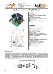
User manual revision 5<strong>AS2.100</strong>As a rule of thumb, sharp dips are diffraction artefacts while sharp peaks are caused by thedrivers themselves. Exceptions are room resonances (if the response is not correctly truncated)and diffractions on repetitive patterns.The second step is designing the actual crossover filters. All the usual strategies work. Delayinghigher frequency drivers with respect to lower-frequency ones is a powerful alternative to usingasymmetric slopes and yields substantially improved coherence through the crossover region.DownloadUnder download the user can press “load DSP” to download its designed filters to the <strong>AS2.100</strong>.This will store the filter settings into the memory of the module.Save FilesUnder filter design there is an option to save all filter settings together with the measurementsso it can be reloaded afterwards. Till now it is not possible to read back the filters out of themodules.During the update from version 1 to 2 of the <strong>Hypex</strong> filter design software we had to make somechanges in the save function. Therefore it is not possible to use save files made in an earlierversion as V2.Firmware updateEvery module has the ability to update its firmware, when <strong>Hypex</strong> provides a new firmwareversion. The firmware version of the module is shown in the statusbar of the filter designwindow and under About.The firmware can be easily updated by USB, the same for master and slave module. Underoption “download” you can find “Firmware update”. When this option is selected the user canselect the new firmware file. This is a complete hex file provided by <strong>Hypex</strong>, no adapts can andmay be made by the user!After the file is selected the update begins.DO NOT DISCONNECT THE MODULE AT THIS PIONT!When the progress bar is filled the update is completed. On a CRC error the update isautomatically restarted, after three errors the update is aborted.Figure 14 shows a completed firmware update.After restarting the module the new firmware is running.Note that the new firmware does not have any filters installed, so the filters must be reloaded with thecorrect values.- 21 -
User manual revision 5<strong>AS2.100</strong>Figure 14- 22 -
User manual revision 5<strong>AS2.100</strong>ExamplesExample 1: 2-channel stereo setupThis example will guide you through setting up you 2-channel stereo system with the AS.100, aschematic presentation of similar setup is given in Figure 6. The master module is always theone with the control panel connected.First you got your 2 modules with no cables or speakers connected!.Master1. Plug- in the power connector and switch the module to ON2. Power up the module by the control panel or remote,Blue LED goes on3. Start the pc program, <strong>Hypex</strong> filter design4. Plug-in the USB cable (assumed that you’ve already installed the software asdescribed in the Software Installation chapter)5. Wait for automatic connection, a popup is displayed as in Figure 8. If the softwaredoesn’t connect automatically press the “connect” button. If there is no responsethere is a problem with the USB connection or your operating system that can notdetect the USB device6. Set the system to the desired setup, for this example a 2-channel where the masterrepresents the Left speakerFigure 157. When needed set the desired input, for now just leave it Auto detect. Note that in autodetect the USB source is selected when the module is connected to the pc8. Switch to the Filter design Window under view, or press ctrl+f9. Fill in your biquads with the desired filters, in this preliminary software the highchannel is channel 1 and the low channel is channel 210. Download the filters to you module under Download, or press ctrl+F9- 23 -
User manual revision 5<strong>AS2.100</strong>Figure 1611. When download is completed you can power down the module12. Start with the SLAVE moduleSlave1. Start the pc program, <strong>Hypex</strong> filter design. Or go back to the control panel (ctrl+c) ifthe program is still running2. Plug- in the power connector and switch the module to ON3. Plug-in the USB cable (assumed that you’ve already installed the software asdescribed in Software Installation chapter)4. Wait for automatic connection, now the program detects a slave module, this isshown in a popup. If connection is not automatic then press the “connect” button. Ifthere is no response there is a problem with the USB connection5. Switch to the Filter design Window under view, or press ctrl+f6. Fill in your biquads with the desired filters or use the same filters as the mastermodule. In this preliminary software the high channel is channel 1 and the lowchannel is channel 27. Download the filters to you module under Download, or press ctrl+F9- 24 -
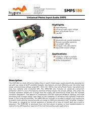
User manual revision 5<strong>AS2.100</strong>8. When download is completed you can power down the module and disconnect theUSB cable9. Master and Slave are now set up as a 2 channel stereo systemFinal setupWhen both modules are installed it is time to complete your setup.- First connect your speakers as explained in chapter Product overview- Connect the trigger cable (mini jack) or SPDIF cable between both modules, dependingon the used audio source- Power up master and slave module- Turn on the master by control panel or remote- Lower you source volume, prevent loud start-up volume- Connect your source to the <strong>AS2.100</strong>Ready!Now the system is fully setup and can be controlled by the control panel, remote control or byconnecting the module to your pc. From now on you can update your filters at any time, justrepeat the Master and Slave steps.* If your slave module is not turned on by the master try to power down the slave, turn themaster off, wait 5 seconds, power up slave and turn the master back on* When there is something that does not work try to repeat the installationExample 2: Stereo setup with active subwooferThis example describes how to set up a stereo passive filtered audio system plus an activesubwoofer (with or without filtering) with use of one <strong>AS2.100</strong>. This setup is shown in Figure 5.At first you have only a <strong>AS2.100</strong> with no cables connected.1. Plug- in the power connector and switch the module to ON2. Power up the module by the control panel or remote3. Start the pc program, <strong>Hypex</strong> filter design4. Plug-in the USB cable (assumed that you’ve already installed the software asdescribed in chapter “- 25 -
User manual revision 5<strong>AS2.100</strong>Software installation” )5. Wait for automatic connection, a popup is displayed as in Figure 8. If connection isnot automatic the press the “connect” button. If there is no response there is aproblem with the USB connection or your operating system that can not detect theUSB device6. Set the system to the desired setup, for this example stereo left because the leftspeaker holds the <strong>AS2.100</strong> module7. Set the Subout control to L+R, because one subwoofer is usedFigure 178. When needed set the desired input, for now just leave it Auto detect. Note that in autodetect the USB source is selected when the module is connected to the pc9. Switch to the Filter design Window under view, or press ctrl+f10. Fill in your biquads with the desired filters. For the stereo setup you don’t need to setany filtering for channel 1(left speaker) and channel 2 (right speaker), but you got theability to use them11. Set your Subwoofer filtering if required12. Even when you don’t want to use the filters you still need to set them to unity. Pressdownload, or use ctrl+F913. When the download is complete the setup is done14. Connect the right speaker to the Amplifier out connector and your subwoofer to theLine out Sub15. Present your audio sourceReady!Now the system is fully setup and can be controlled by the control panel, remote control or byconnecting the module to your pc. From now on you can update your filters at any time, justrepeat the steps of this example.- 26 -
User manual revision 5<strong>AS2.100</strong>Technical dataSupply voltage 230Volt AC/50Hz +/-10%Dimensions115mmx200mmx60mm (WxHxD)Plate thickness2,5mmWeight1,5 kgClearance9mmWarrantyThe work carries warranty out for all provable material and production defects for the duration of 12 monthsstarting from sales. All damage, which is caused by wrong or inappropriate operation, is excluded from thewarranty.DISCLAIMER: This subassembly is designed for use in music reproduction equipment only. Norepresentations are made as to fitness for other uses. Except where noted otherwise anyspecifications given pertain to this subassembly only. Responsibility for verifying theperformance, safety, reliability and compliance with legal standards of end products using thissubassembly falls to the manufacturer of said end product.LIFE SUPPORT POLICY: Use of <strong>Hypex</strong> products in life support equipment or equipment whose failurecan reasonably be expected to result in injury or death is not permitted except by explicit writtenconsent from <strong>Hypex</strong> Electronics BV.- 27 -