USB Based 8-Channel Data Acquisition Module Features Applications
USB Based 8-Channel Data Acquisition Module Features Applications
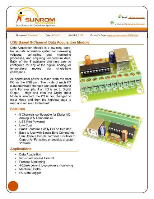
USB Based 8-Channel Data Acquisition Module Features Applications

You also want an ePaper? Increase the reach of your titles
YUMPU automatically turns print PDFs into web optimized ePapers that Google loves.
<strong>Channel</strong> 3 CommandsASCII Character Hex Value Description3 0x33 Dig Out – Set HighE 0x45 Dig Out – Set LowD 0x44 Digital InputC 0x43 Analog In- 0x2D Temperature<strong>Channel</strong> 4 CommandsASCII Character Hex Value Description4 0x34 Dig Out – Set HighR 0x52 Dig Out – Set LowF 0x46 Digital InputV 0x56 Analog In= 0x3D Temperature<strong>Channel</strong> 5 CommandsASCII Character Hex Value Description5 0x35 Dig Out – Set HighT 0x54 Dig Out – Set LowG 0x47 Digital InputB 0x42 Analog InO 0x4F Temperature<strong>Channel</strong> 6 CommandsASCII Character Hex Value Description6 0x36 Dig Out – Set HighY 0x59 Dig Out – Set LowH 0x48 Digital InputN 0x4E Analog InP 0x50 Temperature<strong>Channel</strong> 7 CommandsASCII Character Hex Value Description7 0x37 Dig Out – Set HighU 0x55 Dig Out – Set LowJ 0x4A Digital InputM 0x4D Analog In[ 0x5B Temperature<strong>Channel</strong> 8 CommandsASCII Character Hex Value Description8 0x38 Dig Out – Set HighI 0x49 Dig Out – Set LowK 0x4B Digital Input,0x2C Analog In(Comma)] 0x5D TemperaturePing CommandsASCII Character Hex Value Description@ 0x40 Issue Ping #(0x23) Hash character will be returned if the unitis found on selected port3Sunrom Technologies Your Source for Embedded Systems Visit us at www.sunrom.com
Interfacing with boardPush to On Switch – If you wish to connect a push to on switch to any of the IO1 to 8 then you canuse this method. When switch is off the 10K resistor will keep the IO pin high, When switch ispressed on the switch will ground the IO pin. You can use digital input command to read this status.Board#1169IOxIOx readas digitalinputcommand+5V OUTGND10KLED – Any IO can be connected with LED like below. You can use digital output set high/lowcommand to set status of LED.Board#1169IOx is setHigh/low asPer commandfrom PCIOx+5V OUTGND 470Buzzer – Self Oscillating type buzzer(piezo or coil type) can be connected to any IO. If using coiltype buzzer, a diode should be used across buzzer to discharge its coil of high voltage duringoperation. In following diagram making a pin low will cause the buzzer to sound. Making an IO highwill switch off the buzzer. Alternately you can also connect buzzer between IO and GND pin.Board#1169IOx is setHigh/low asPer commandfrom PCIOx+5V OUTGNDMeasure Temperature using LM35 Sensor- LM35 is a temperature sensor will gives analogvoltage for 10mV per degree Celsius. At 25°C you get 250mV output analog voltage. If you read thevoltage with the board using analog read command you will get for example 0.250V output.Since the sensor outputs analog voltage the wire connect to sensor & board cannot be more than 2meters. In next method we will show how to measure temperature at over distance of 300 feet usingCAT5 cable and DS18B20 temperature sensor.Board#1169IOx readsAnalogVoltageIOx+5V OUTGND4Sunrom Technologies Your Source for Embedded Systems Visit us at www.sunrom.com
Measure Temperature using DS18B20 Temperature SensorBoard#1169IOx readsTemperaturefromDS18B20IOx+5V OUTGND1KDS18B20 can be connected to measure temperatures from -55°C to +125°C (-67°F to+257°F) with ±0.5°C Accuracy from -10°C to +85°CUp to eight DS18B20 digital temperature sensors can be connected to the board. The length ofcable can be upto 300 feet(100 meters). For best performance, use Cat 5 type computer cable(alsocalled Ethernet/LAN Cable) to connect the sensors to the board. Two pairs of wires in the Cat 5cable are required for the connection. The first pair is for Power (5V) and Ground, and the secondpair is designated as <strong>Data</strong> and Ground. In addition, a pull-up resistor is required for the data line ofapproximately 1K Ohms.Reading Temperature will return valid temperature data if a temperature sensor is connected to thespecified I/O port. If no sensor is connected, a Temperature command will always return 999.99°.Cat5 cable lengths of greater that 100 feet may require a pullup resistor value of less than 1K Ohmsin order to achieve usable rise times at the sensor. The minimum safe resistance for the pullupresistor is 240 Ohms.Sending read temperature command will returns current temperature in Celsius and FahrenheitExample reading: 31.8°C 89.24°F4-20ma Current Loop - Many industrial systems uses current signals to monitor certain devices(like pressure sensors, gas detectors, temperature sensors). The signal is transported over 2 wires.The advantage of working with currents is a current always remains the same, no matter what thelength of a wire is.Most sensors can output a current signal between 4 and 20 mA. A signal lower than 4mA, typicallyindicates an error.This method below allows you to log a 4 - 20mA signal coming from a sensor. The 4-20mA currentis converted into voltage in range of 0-5V. Read analog values on the channel where this signal isconnected. When the current is 4mA the board will read analog voltage as 0.88V, When the currentis 20mA the board will read 4.4VBoard#1169IOx configuredfor AnalogVoltageReadingIOx+5V OUTGND220R+4-20 mASource orSensor-5Sunrom Technologies Your Source for Embedded Systems Visit us at www.sunrom.com
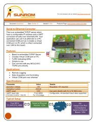
Absolute Maximum RatingsStresses above those listed here may cause permanent damage to the unit:• Operating Temperature: 0-70°C• Voltage on I/Os with Respect to Ground: -0.3V to +5.3V• Sink/Source Current on Any I/O: 25mAWarnings• Unplug unit from the PC before connecting any interfaces to board terminal.• Isolate the bottom of the board from all conductive surfaces.• Observe static precautions to prevent damage to the module.<strong>USB</strong> Driver<strong>USB</strong> drivers for the following operating systems are available for download from our website:Windows XP, Windows7-32 Bit and 64 BitDownload <strong>USB</strong> Driver from below link, It has readme text file to help you with instructions to install.http://www.sunrom.com/files/ST3683-driver-setup.zipFirst connect Board to PC then start <strong>USB</strong> Driver Setup.You can open Start > Device and Printer menu to see the installed Port to which software canconnect. A com port should also appears in Device Manager under Ports.Board is detectedby PC as VirtualCom Port6Sunrom Technologies Your Source for Embedded Systems Visit us at www.sunrom.com
Mechanical DimensionsDimensions in mm7Sunrom Technologies Your Source for Embedded Systems Visit us at www.sunrom.com