GPS Receiver - Sunrom Technologies
GPS Receiver - Sunrom Technologies
GPS Receiver - Sunrom Technologies

Create successful ePaper yourself
Turn your PDF publications into a flip-book with our unique Google optimized e-Paper software.
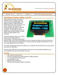
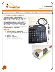
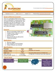
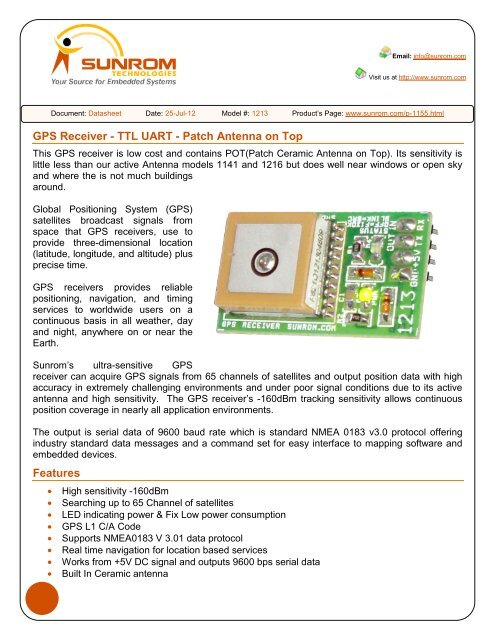
Email: info@sunrom.comVisit us at http://www.sunrom.comDocument: Datasheet Date: 25-Jul-12 Model #: 1213 Product’s Page: www.sunrom.com/p-1155.html<strong>GPS</strong> <strong>Receiver</strong> - TTL UART - Patch Antenna on TopThis <strong>GPS</strong> receiver is low cost and contains POT(Patch Ceramic Antenna on Top). Its sensitivity islittle less than our active Antenna models 1141 and 1216 but does well near windows or open skyand where the is not much buildingsaround.Global Positioning System (<strong>GPS</strong>)satellites broadcast signals fromspace that <strong>GPS</strong> receivers, use toprovide three-dimensional location(latitude, longitude, and altitude) plusprecise time.<strong>GPS</strong> receivers provides reliablepositioning, navigation, and timingservices to worldwide users on acontinuous basis in all weather, dayand night, anywhere on or near theEarth.<strong>Sunrom</strong>’s ultra-sensitive <strong>GPS</strong>receiver can acquire <strong>GPS</strong> signals from 65 channels of satellites and output position data with highaccuracy in extremely challenging environments and under poor signal conditions due to its activeantenna and high sensitivity. The <strong>GPS</strong> receiver’s -160dBm tracking sensitivity allows continuousposition coverage in nearly all application environments.The output is serial data of 9600 baud rate which is standard NMEA 0183 v3.0 protocol offeringindustry standard data messages and a command set for easy interface to mapping software andembedded devices.Features• High sensitivity -160dBm• Searching up to 65 Channel of satellites• LED indicating power & Fix Low power consumption• <strong>GPS</strong> L1 C/A Code• Supports NMEA0183 V 3.01 data protocol• Real time navigation for location based services• Works from +5V DC signal and outputs 9600 bps serial data• Built In Ceramic antenna
Applications• Car Navigation and Marine Navigation, Fleet Management• Automotive Navigator Tracking, Vehicle Tracking• AVL and Location-Based Services• Auto Pilot, Personal Navigation or touring devices• Tracking devices/systems and Mapping devices application Emergency Locator• Geographic Surveying• Personal Positioning• Sporting and Recreation• Embedded applications which needs to be aware of its location on earthSpecificationParameter Value UnitOperating Voltage 5 V Regulated DCPower SupplyOperating Current 50 mASensitivity -160 dBmChannels 65 65 parallel channels all in view searchingL1 C/A codeProtocol output baud rate 9600 bps no handshaking(8-N-1)Protocol format NMEA0183 V 3.01 GGA,GLL,GSA,GSV,RMC,VTGOutput Voltage level +3V (+5V Tolerant) Can connect directly to microcontrollerworking at 5V or 3VFrequency 1,1575.42 MhzC/A Code 1.023 Mhz chip rateAccuracy in Position 5 MetersAccuracy in Velocity 0.1 Meters/SecondAccuracy in Time 0.1 Microsecond. Sync <strong>GPS</strong> timeDatum WGS84(Default) total 219 datum’sTime to First Fix for first power on 33 Second approx.Time to Reacquisition 2 SecondUpdate Rate 1 HzAcceleration Limit 4 GAltitude Limit 18,000 MetersVelocity Limit 515 Meters/SecondJerk Limit 20 Meters/Second 3Operating Temperature -40 to +85 Degree Celcius2<strong>Sunrom</strong> <strong>Technologies</strong> Your Source for Embedded Systems Visit us at www.sunrom.com
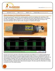
Software for monitoring <strong>GPS</strong> dataThe NMEA data from <strong>GPS</strong> unit can be monitored by following or other similar.Download <strong>GPS</strong> monitoring softwarehttp://www.sunrom.com/files/TrimbleStudio_V1-01-21.exeCreate“New Connection…”Select COM port to which <strong>GPS</strong>is connected and configuresetting for 9600Position of <strong>GPS</strong>Click Monitor >SKY Plot to seewhat satellites arelocated3Click Monitor > RAW Data tosee what <strong>GPS</strong> receiver issending raw serial data.It takes around 5-10 minutes fordata to be shown after power up.<strong>Sunrom</strong> <strong>Technologies</strong> Your Source for Embedded Systems Visit us at www.sunrom.com
Using <strong>GPS</strong> <strong>Receiver</strong>The connector of <strong>GPS</strong> contains four terminals• GND• +5V• TX = Out• RX = InputThese connections are marked on the PCB.Provide regulated +5V DC supply to +5V andGround.The TX output wire can be connected to microcontroller RXD pin directly.The RX input pin has special purpose in the sense it can be used to send commands regardingoperation of <strong>GPS</strong> like changing baud rate. This can be done through Trimble software. It is notrequired to be connected to microcontroller.The GREEN Power LED indicates that <strong>GPS</strong> is getting power.The RED LED indicates if blinking that it is searching for satellites. If it becomes off means it hasfound a fix with satellite and data contains position and other data. When you power on it will blinkfor a while then it will become off.Note: Do not connect TXD output pin to serial port of PC directly, it needs a MAX232 levelconversion circuit since the unit has 5V level output signal.Following pages described some hardware connection examplesBoard Dimensions4<strong>Sunrom</strong> <strong>Technologies</strong> Your Source for Embedded Systems Visit us at www.sunrom.com
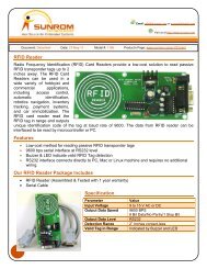
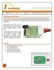
Connecting <strong>GPS</strong> <strong>Receiver</strong> to MicrocontrollerHere is an example of interfacing with microcontroller AT89S52 having UART at 5V level. Configureyour microcontroller to communicate at 9600 baud rate and parse the incoming data.VCCTTL UART INTERFACINGVCCC810uF 16VR110K39383736353433321234567831+9U2AT89S52P0.0/AD0P0.1/AD1P0.2/AD2P0.3/AD3P0.4/AD4P0.5/AD5P0.6/AD6P0.7/AD7P1.0/T2P1.1/T2EXP1.2P1.3P1.4/SSP1.5/MOSIP1.6/MISOP1.7/SCKEA/VPPRSTGND20VCC 40XTAL119C1100nP2.0/A8P2.1/A9P2.2/A10P2.3/A11P2.4/A12P2.5/A13P2.6/A14P2.7/A1510P3.0/RXDP3.1/TXD 1112P3.2/INT013P3.3/INT114P3.4/T015P3.5/T116P3.6/WR17P3.7/RDXTAL2182122232425262728PSEN 29ALE/PROG 30Y1U4<strong>Sunrom</strong> <strong>GPS</strong> <strong>Receiver</strong> Model#1213RX-INTX-OUT+5VGND4321VCCC933p11.0592C1033p5<strong>Sunrom</strong> <strong>Technologies</strong> Your Source for Embedded Systems Visit us at www.sunrom.com
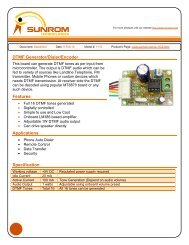
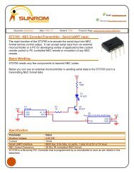
Interfacing with RS232If you wish to interface the module with RS232 level like a PC serial port or any other device youneed a level convertor such as MAX232 as shown below.U5<strong>Sunrom</strong> <strong>GPS</strong> <strong>Receiver</strong> Model#1213RX-INTX-OUT+5VGND4321VCCRS232 INTERFACINGC1310uF 16VC1410uF 16V++VCC1191210132U6MAX232T1INR2OUTR1OUTT2INC+V+VCCVCC 16GND15T1OUTR2INR1INT2OUTC2+C1-C2-C16100nV-148137456++C1210uF 16VC1510uF 16VP2DB9-CONN-F162738495You can also use ourMax232 Board Model 1104http://www.sunrom.com/p-245.htmlInterfacing to USB Port and Powering from USB PortU9<strong>Sunrom</strong> <strong>GPS</strong> <strong>Receiver</strong> Model#1213RX-INTX-OUT+5VGND4321U8USB to Serial Board SUNROM#1151/1192RX-INTX-OUTGND+5V1234You can use ourUSB to Serial BoardModel 1151 or 11921151 model plugs in directly to USBport of PCUSB INTERFACINGOur USB to Serial TLL will appear as virtual serial port on PC towhich you can communicate through any software which cantransmit receive by this serial port like hyperterminal orcustom made software like Trimble <strong>GPS</strong>.http://www.sunrom.com/p-244.htmlSimilar model to above but needs aUSB A-B Type cablehttp://www.sunrom.com/p-1145.html6<strong>Sunrom</strong> <strong>Technologies</strong> Your Source for Embedded Systems Visit us at www.sunrom.com
<strong>GPS</strong> IntroductionThe Global Positioning System (<strong>GPS</strong>) is global navigation satellite system which uses aconstellation of between 24 and 32 Medium Earth Orbit satellites that transmit precise microwavesignals, that enable <strong>GPS</strong> receivers to determine their location, speed, direction, and time.<strong>GPS</strong> has become a widely used aid to navigation worldwide, and a useful tool for map-making, landsurveying, commerce, scientific uses, tracking and surveillance, and hobbies such as geo-cachingand way marking. Also, the precise time reference is used in many applications including thescientific study of earthquakes and as a time synchronization source for cellular network protocols.<strong>GPS</strong> has become a mainstay of transportation systems worldwide, providing navigation for aviation,ground, and maritime operations. Disaster relief and emergency services depend upon <strong>GPS</strong> forlocation and timing capabilities in their life-saving missions. The accurate timing that <strong>GPS</strong> providesfacilitates everyday activities such as banking, mobile phone operations, and even the control ofpower grids. Farmers, surveyors, geologists and countless others perform their work moreefficiently, safely, economically, and accurately using the free and open <strong>GPS</strong> signals.<strong>GPS</strong> Method of OperationA <strong>GPS</strong> receiver calculates its position by carefully timing the signals sent by the constellation of<strong>GPS</strong> satellites high above the Earth. Each satellite continually transmits messages containing thetime the message was sent, a precise orbit for the satellite sending the message (the ephemeris),and the general system health and rough orbits of all <strong>GPS</strong> satellites (the almanac). These signalstravel at the speed of light through outer space, and slightly slower through the atmosphere. Thereceiver uses the arrival time of each message to measure the distance to each satellite therebyestablishing that the <strong>GPS</strong> receiver is approximately on the surfaces of spheres centered at eachsatellite. The <strong>GPS</strong> receiver also uses, when appropriate, the knowledge that the <strong>GPS</strong> receiver is on(if vehicle altitude is known) or near the surface of a sphere centered at the earth center. Thisinformation is then used to estimate the position of the <strong>GPS</strong> receiver as the intersection of spheresurfaces. The resulting coordinates are converted to a more convenient form for the user such aslatitude and longitude, or location on a map, then displayed.It might seem that three sphere surfaces would be enough to solve for position, since space hasthree dimensions. However a fourth condition is needed for two reasons. One has to do withposition and the other is to correct the <strong>GPS</strong> receiver clock.It turns out that three sphere surfaces usually intersect in two points. Thus a fourth sphere surface isneeded to determine which intersection is the <strong>GPS</strong> receiver position. For near earth vehicles, thisknowledge that it is near earth is sufficient to determine the <strong>GPS</strong> receiver position since for thiscase there is only one intersection which is near earth.A fourth sphere surface is also needed to correct the <strong>GPS</strong> receiver clock. More precise informationis needed for this task. An estimate of the radius of the sphere is required. Therefore anapproximation of the earth altitude or radius of the sphere centered at the satellite must be known.7<strong>Sunrom</strong> <strong>Technologies</strong> Your Source for Embedded Systems Visit us at www.sunrom.com
Block DiagramActive AntennaLow Noise AmpSAW<strong>GPS</strong> RF Front End<strong>GPS</strong> Base BandNMEA Serial DataTXCOThe <strong>GPS</strong> <strong>Receiver</strong> consist of two units, first is active antenna which receives RF signals andamplifies it. The antenna is active in the sense it takes power from the module and amplifies thesignal for high sensitivity. The RF signal is filtered and processed to generate NMEA format serialdata output.General <strong>GPS</strong> <strong>Receiver</strong> User’s Tips• If the satellite signals cannot be locked or experiencing receiving problem (while in urbanarea), following steps are suggested:o a) Please relocate the <strong>GPS</strong> receiver near window or open sky for better receivingperformance.o b) Move to another open space or reposition <strong>GPS</strong> receiver toward the direction withleast blockage.o c) Move the <strong>GPS</strong> receiver away from the interference sources.o d) Wait until the weather condition is improved.• Some vehicles having heavy metallic sun protecting coating on windshields may affect signalreceptions• Driving in and around high buildings may affect signal reception.• Driving under tunnels or in buildings may affect signal reception.• In general, <strong>GPS</strong> receiver performs best in open space where it can see clean sky. Weatherwill affect <strong>GPS</strong> reception – rain & snow contribute to worsen sensitivity.• When <strong>GPS</strong> receiver is moving, it will take longer time to get position fix. Wait for satellitesignals to be locked at a fixed point when first power-on the <strong>GPS</strong> receiver to ensure quick<strong>GPS</strong> position fix.Related links<strong>GPS</strong> Introductionhttp://en.wikipedia.org/wiki/Introduction_to_the_Global_Positioning_System<strong>GPS</strong> Working Detailshttp://en.wikipedia.org/wiki/Global_Positioning_Systemhttp://en.wikipedia.org/wiki/<strong>GPS</strong><strong>GPS</strong> - NMEA sentence informationhttp://home.mira.net/~gnb/gps/nmea.htmlAVR Library for parsing <strong>GPS</strong> Datahttp://www.mil.ufl.edu/~chrisarnold/components/microcontrollerBoard/AVR/avrlib/docs/html/nmea_8c.html8<strong>Sunrom</strong> <strong>Technologies</strong> Your Source for Embedded Systems Visit us at www.sunrom.com
Interface to <strong>GPS</strong> - Articlehttp://www.kronosrobotics.com/Projects/<strong>GPS</strong>.shtmlAVR Project and Source codehttp://www.avrfreaks.net/index.php?module=Freaks%20Academy&func=viewItem&item_id=1062&item_type=project×tamp=2007-08-19%2015:46:24NMEA MessagesThe serial interface protocol is based on the National Marine Electronics Association’s NMEA 0183ASCII interface specification. This standard is fully define in “NMEA 0183, Version 3.01” Thestandard may be obtained from NMEA, www.nmea.orgNMEA ProtocolThis section provides a brief overview of the NMEA 0183 protocol, and describes both the standardand optional messages offered by the <strong>GPS</strong> <strong>Receiver</strong>.NMEA 0183 is a simple, yet comprehensive ASCII protocol which defines both the communicationinterface and the data format. The NMEA 0183 protocol was originally established to allow marinenavigation equipment to share information. Since it is a well established industry standard, NMEA0183 has also gained popularity for use in applications other than marine electronics. The <strong>GPS</strong>receiver supports the latest release of NMEA 0183, Version 3.0 (July 1, 2000). The primary changein release 3.0 is the addition of the mode indicators in the GLL, RMC, and VTG messages.For those applications requiring output only from the <strong>GPS</strong> receiver, the standard NMEA 0183sentences are a popular choice. Many standard application packages support the standard NMEAoutput messages.The standard NMEA output only messages are: GGA, GLL, GSA, GSV, RMC, VTC, and ZDA.NMEA RECORDGGAGLLGSAGSVRMCVTGZDADescription<strong>GPS</strong> fix dataGeographicGNSS DOP and active satelliteGNSS Satellites in viewRecommended minimum specific GNSS dataCourse Over Ground and Ground SpeedTime&Data9<strong>Sunrom</strong> <strong>Technologies</strong> Your Source for Embedded Systems Visit us at www.sunrom.com
NMEA 0183 Message FormatThe NMEA 0183 protocol covers a broad array of navigation data. The entire protocol encompassesover 50 messages, but only a sub-set of these messages apply to this <strong>GPS</strong> receiver. TheNMEA message structure is described below.$IDMSG,D1,D2,D3,D4,.......,Dn*CS[CR][LF]“$” The “$” signifies the start of a message.ID The identification is a two letter mnemonic which describes the source of the navigationinformation. The GP identification signifies a <strong>GPS</strong> source.MSG The message identification is a three letter mnemonic which describes the message content andthe number and order of the data fields.“,” Commas serve as delimiters for the data fields.Dn Each message contains multiple data fields (Dn) which are delimited by commas. The length ofthe fields can be variable.“*” The asterisk serves as a checksum delimiter.CS The checksum field contains two ASCII characters which indicate the hexadecimal value of thechecksum.[CR][LF] The carriage return [CR] and line feed [LF] combination terminate the message.NMEA 0183 standard messages vary in length, but each message is limited to 79 characters orless. This length limitation excludes the “$” and the [CR][LF]. The standard message data fieldblock, including delimiters, is limited to 74 characters or less.10<strong>Sunrom</strong> <strong>Technologies</strong> Your Source for Embedded Systems Visit us at www.sunrom.com
GGA - Global Positioning System Fix DataTime, position and fix related data for a <strong>GPS</strong> receiver.Structure:$GPGGA,hhmmss.sss,ddmm.mmmm,a,dddmm.mmmm,a,x,xx,x.x,x.x,M,,,,xxxx*hhField 1 2 3 4 5 6 7 8 9 10 11Example:$GPGGA,111636.932,2447.0949,N,12100.5223,E,1,11,0.8,118.2,M,,,,0000*02Field 1 2 3 4 5 6 7 8 9 10 11Field Name Example Description1 UTC Time 111636.932 UTC of position in hhmmss.sss format, (000000.000 ~235959.999)2 Latitude 2447.0949 Latitude in ddmm.mmmm formatLeading zeros transmitted3 N/S Indicator N Latitude hemisphere indicator, ‘N’ = North, ‘S’ = South4 Longitude 12100.5223 Longitude in dddmm.mmmm formatLeading zeros transmitted5 E/W Indicator E Longitude hemisphere indicator, 'E' = East, 'W' = West6 <strong>GPS</strong> qualityindicator1 <strong>GPS</strong> quality indicator0: position fix unavailable1: valid position fix, SPS mode2: valid position fix, differential <strong>GPS</strong> mode3: <strong>GPS</strong> PPS Mode, fix valid4: Real Time Kinematic. System used in RTK mode with fixedintegers5: Float RTK. Satellite system used in RTK mode. Floatingintegers6: Estimated (dead reckoning) Mode7: Manual Input Mode8: Simulator Mode7 Satellites Used 11 Number of satellites in use, (00 ~ 12)8 HDOP 0.8 Horizontal dilution of precision, (00.0 ~ 99.9)9 Altitude 108.2 mean sea level (geoid), (-9999.9 ~ 17999.9)10 D<strong>GPS</strong> Station ID 0000 Differential reference station ID, 0000 ~ 1023NULL when D<strong>GPS</strong> not used11 Checksum 02Note: The checksum field starts with a ‘*’ and consists of 2 characters representing a hex number.The checksum is the exclusive OR of all characters between ‘$’ and ‘*’.11<strong>Sunrom</strong> <strong>Technologies</strong> Your Source for Embedded Systems Visit us at www.sunrom.com
GLL – Latitude/LongitudeLatitude and longitude of current position, time, and status.Structure:$GPGLL,ddmm.mmmm,a,dddmm.mmmm,a,hhmmss.sss,A,a*hhField 1 2 3 4 5 6 7 8Example:$GPGLL,2447.0944,N,12100.5213,E,112609.932,A,A*57Field 1 2 3 4 5 6 7 8Field Name Example Description1 Latitude 2447.0944 Latitude in ddmm.mmmm formatLeading zeros transmitted2 N/S Indicator N Latitude hemisphere indicator‘N’ = North‘S’ = South3 Longitude 12100.5213 Longitude in dddmm.mmmm formatLeading zeros transmitted4 E/W Indicator E Longitude hemisphere indicator'E' = East'W' = West5 UTC Time 112609.932 UTC time in hhmmss.sss format (000000.000 ~ 235959.999)6 Status A Status, ‘A’ = Data valid, ‘V’ = Data not valid7 Mode Indicator A Mode indicator‘N’ = Data not valid‘A’ = Autonomous mode‘D’ = Differential mode‘E’ = Estimated (dead reckoning) mode‘M’ = Manual input mode‘S’ = Simulator mode8 Checksum 5712<strong>Sunrom</strong> <strong>Technologies</strong> Your Source for Embedded Systems Visit us at www.sunrom.com
Other NMEA Message output13<strong>Sunrom</strong> <strong>Technologies</strong> Your Source for Embedded Systems Visit us at www.sunrom.com
14<strong>Sunrom</strong> <strong>Technologies</strong> Your Source for Embedded Systems Visit us at www.sunrom.com
15<strong>Sunrom</strong> <strong>Technologies</strong> Your Source for Embedded Systems Visit us at www.sunrom.com