VP 6-in In-Ceiling Instruction Manual_Final6.qxp - Sonance
VP 6-in In-Ceiling Instruction Manual_Final6.qxp - Sonance
VP 6-in In-Ceiling Instruction Manual_Final6.qxp - Sonance

You also want an ePaper? Increase the reach of your titles
YUMPU automatically turns print PDFs into web optimized ePapers that Google loves.
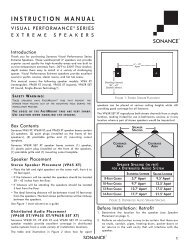
SONANCE VISUAL PERFORMANCE ®6” IN-CEILINGStereo Placement (2-Channel)• Place the left and right speakers anywhere from 6 feet to 10feet apart, with the ma<strong>in</strong> listen<strong>in</strong>g position as close to midwaybetween the speakers as possible.• <strong>In</strong> most cases pivot<strong>in</strong>g the woofer of each speaker directlytowards the ma<strong>in</strong> listen<strong>in</strong>g position will help maximize thestereo soundstage.Use the Left and Right speaker placement <strong>in</strong> Figures 2 and 3(on page 1) as a guide.Before <strong>In</strong>stallation1. Determ<strong>in</strong>e the location for the speaker (see Speaker Placementon page 1).2. Perform an obstruction survey to be certa<strong>in</strong> that there are nostuds, conduit, pipes, heat<strong>in</strong>g ducts, pocket doors or air returns<strong>in</strong> the ceil<strong>in</strong>g cavity that will <strong>in</strong>terfere with the speaker.3. Visual Performance Series 6” <strong>in</strong>-ceil<strong>in</strong>g speakers have thefollow<strong>in</strong>g mount<strong>in</strong>g space requirements:• <strong>VP</strong>69R/<strong>VP</strong>67R/<strong>VP</strong>65R: 8 5 / 32 ” (207mm) diameter mount<strong>in</strong>ghole with at least 4¾” (121mm) depth with<strong>in</strong> the mount<strong>in</strong>gcavity.• <strong>VP</strong>65S/<strong>VP</strong>65STL: 8 5 / 32 ” x 8 5 / 32 ” (207mm x 207mm) mount<strong>in</strong>ghole. The <strong>VP</strong>65S requires at least 4 13 /16” (122mm) depthwith<strong>in</strong> the mount<strong>in</strong>g cavity; the <strong>VP</strong>65STL requires at least 3 1 /32”(77mm) depth with<strong>in</strong> the mount<strong>in</strong>g cavity.• <strong>VP</strong>65RTL: 8 5 /32” diameter mount<strong>in</strong>g hole with at least 3 1 /32”(77mm) depth with<strong>in</strong> the mount<strong>in</strong>g cavity.4. Position the <strong>in</strong>cluded cutout template where the speaker is tobe located and pencil an outl<strong>in</strong>e on the ceil<strong>in</strong>g.• If you are unsure about obstructions, drill a small hole <strong>in</strong> thecenter of the outl<strong>in</strong>e and <strong>in</strong>sert a coat hanger wire <strong>in</strong>to thehole to feel-around for possible obstructions.5. Cut the mount<strong>in</strong>g hole us<strong>in</strong>g a keyhole or drywall saw, andrun the speaker wires from the mount<strong>in</strong>g hole to the amplifierlocation.• Consult local build<strong>in</strong>g codes before runn<strong>in</strong>g speaker wiresthrough ceil<strong>in</strong>gs.<strong>In</strong>stallation<strong>Sonance</strong> Visual Performance Series speakers feature exclusiveFastMount ® tabs and an <strong>in</strong>tegral RotoLock ® mount<strong>in</strong>g system forquick mount<strong>in</strong>g directly <strong>in</strong>to exist<strong>in</strong>g ceil<strong>in</strong>gs.WARNING: THE EDGES OF THE FASTMOUNT TABSARE VERY SHARP. USE CAUTION WHEN HANDLINGTHE SPEAKER.1. Remove the pa<strong>in</strong>t plug from the speaker.2. Strip ¼” – ½” of <strong>in</strong>sulation from each speaker lead. Twist thestrands or t<strong>in</strong> the exposed wire with solder to ensure that thereare no stray strands. (Stray strands that touch each other cancause a short-circuit that can damage the amplifier.)3. The speaker’s connector posts are spr<strong>in</strong>g-loaded. Push the topof each connector post down to open the connector and <strong>in</strong>sertthe exposed wires <strong>in</strong>to the holes <strong>in</strong> the posts.• The speaker’s positive post is labeled with a red dot; thenegative post is labeled with a black dot. Double-check thatyou connected amplifier “+” to speaker “+” and amplifier “–”to speaker “–”.24. Make sure all theRotoLock clamps areretracted so that theyare tucked with<strong>in</strong> themount<strong>in</strong>g hole’s border.<strong>In</strong>sert the speaker <strong>in</strong>tothe hole <strong>in</strong> the ceil<strong>in</strong>g(Figure 4). TheRotoLock system canaccommodate a maximumceil<strong>in</strong>g materialthickness of 1¼”.• The FastMount tabswill prevent thespeaker from fall<strong>in</strong>gout of the mount<strong>in</strong>ghole, allow<strong>in</strong>g the<strong>in</strong>staller to let go ofthe speaker to pick-uptools or other items(Figure 5).NOTE: THE FASTMOUNTTABS ARE DESIGNEDFOR ONE-TIME USEONLY. IF THE SPEAKER ISREMOVED FROM THEMOUNTING HOLE THEFASTMOUNT TABS WILLDISCONNECT ANDREMAIN INSIDE THECEILING.5. Tighten the four screwson the front of thespeaker baffle. TheRotoLock clamps willautomatically rotate<strong>in</strong>to position and beg<strong>in</strong>clamp<strong>in</strong>g the speaker(Figure 6).• When you noticeresistance on thescrews the speakerhas been clampedsuccessfully.IMPORTANT:Always use lowtorquesett<strong>in</strong>gs;NEVER overtighten.RotoLock Clamps(retracted)FIGURE 4: INSERTING THE SPEAKERINTO THE MOUNTING HOLEFastMount TabsFIGURE 5:FASTMOUNT TABSRotoLock Clamps(extended)FIGURE 6:TIGHTENING THE ROTOLOCK CLAMPSNOTE: ADJUSTING THE TENSION OF THE ROTOLOCK CLAMPSSO THAT THE SPEAKER FRAME IS FLAT WILL HELP ENSURE THATTHE GRILLE CONTACTS THE CEILING ALL THE WAY AROUND THESPEAKER FOR A PROPER FIT.6. The new micro flange grille is held <strong>in</strong> place by several small,powerful magnets on the speaker frame. Place the grilleaga<strong>in</strong>st the speaker and the magnets will hold it firmly <strong>in</strong>place. When properly <strong>in</strong>stalled, the grille flange should makecontact with the wall all the way around the speaker.