VP 6-in In-Ceiling Instruction Manual_Final6.qxp - Sonance
VP 6-in In-Ceiling Instruction Manual_Final6.qxp - Sonance
VP 6-in In-Ceiling Instruction Manual_Final6.qxp - Sonance

You also want an ePaper? Increase the reach of your titles
YUMPU automatically turns print PDFs into web optimized ePapers that Google loves.
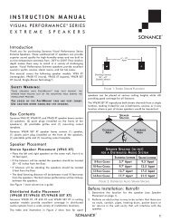
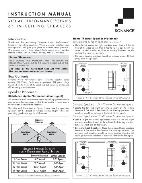
INSTRUCTION MANUALVISUAL PERFORMANCE ® SERIES6” IN-CEILING SPEAKERS<strong>In</strong>troductionThank you for purchas<strong>in</strong>g <strong>Sonance</strong> Visual Performance ®Series 6” <strong>in</strong>-ceil<strong>in</strong>g speakers. When properly <strong>in</strong>stalled yournew speakers will give you years of enterta<strong>in</strong>ment pleasure.This manual covers these Visual Performance series speakermodels: <strong>VP</strong>69R, <strong>VP</strong>67R, <strong>VP</strong>65R, <strong>VP</strong>65S, <strong>VP</strong>65RTL, <strong>VP</strong>65STL .SAFETY WARNING:THESE SPEAKERS HAVE FASTMOUNT ® TABS THAT PREVENT THESPEAKER FROM FALLING OUT OF THE MOUNTING HOLE DURING THEINSTALLATION PROCESS.THE EDGES OF THE FASTMOUNT TABS ARE VERY SHARP.U SE CAUTION WHEN HANDLING THE SPEAKER.Home Theater Speaker PlacementLeft, Center & Right Speakers (see Figure 2)• Place the left, center and right speakers from 1 foot to 2 feet <strong>in</strong>front of the video screen, from 6 feet to 10 feet apart, with thecenter channel speaker as close to midway between the leftand right speakers as possible.• The ma<strong>in</strong> listen<strong>in</strong>g position should be between 4 and 10 feetaway from the speakers.Left, Center& RightSpeakersLeft & RightSurroundSpeakersBox Contents<strong>Sonance</strong> Visual Performance Series <strong>in</strong>-ceil<strong>in</strong>g speaker boxesconta<strong>in</strong> (2) Visual Performance speakers, (2) pa<strong>in</strong>t plugs(<strong>in</strong>stalled on the fronts of the speakers), (2) pa<strong>in</strong>table grilles and(1) mount<strong>in</strong>g cutout template.TV1'– 2'6'– 10'Apart2' – 6'6' – 10'ApartSpeaker PlacementDistributed Audio Placement (Mono signal)All <strong>Sonance</strong> Visual Performance Series <strong>in</strong>-ceil<strong>in</strong>g speaker modelsprovide excellent coverage <strong>in</strong> distributed audio systems from awide variety of <strong>in</strong>stallation locations.The table and illustration <strong>in</strong> Figure 1 show how far apart thespeakers can be placed at various ceil<strong>in</strong>g heights while stillprovid<strong>in</strong>g good coverage for all listeners.COVERAGEAREASPEAKERSPACINGCOVERAGEAREALess than 2’FIGURE 2: 5.1-CHANNEL HOME THEATER SPEAKER PLACEMENTSurround Speakers — 5.1-Channel System (see Figure 2)• Locate the left and right surround speakers on the ceil<strong>in</strong>gbetween 2 feet and 6 feet beh<strong>in</strong>d the listen<strong>in</strong>g position. Thespeakers should be between 6 feet and 10 feet apart.Surround Speakers — 7.1-Channel System (see Figure 3)• Left & Right Surround Speakers: Place the left and rightsurround speakers directly to the sides of the listen<strong>in</strong>g position,between 6 feet and 10 feet apart.• Surround Back Speakers: Place the surround back speakersbetween 2 feet and 6 feet beh<strong>in</strong>d the listen<strong>in</strong>g position. Thesurround back speakers should be closer together than the leftand right surround speakers — between 3 feet and 6 feet apart.S PEAKER SPACING (IN FEET)FOR A DISTRIBUTED AUDIO SYSTEMLeft, Center& RightSpeakersLeft & RightSurround SpeakersSurroundBackSpeakers8-FOOT CEILING10-FOOT CEILINGSTANDING LISTENER5.7’ Apart9.7’ ApartSEATED LISTENER9.5’ Apart13.5’ ApartTV1'– 2'6' – 10'Apart2' – 6'3' – 6'Apart12-FOOT CEILING13.7’ Apart17.5’ Apart14-FOOT CEILING17.7’ Apart21.5’ ApartLess than 2’FIGURE 1: DISTRIBUTED AUDIO SPEAKER SPACINGFIGURE 3: 7.1-CHANNEL HOME THEATER SPEAKER PLACEMENT
SONANCE VISUAL PERFORMANCE ®6” IN-CEILINGStereo Placement (2-Channel)• Place the left and right speakers anywhere from 6 feet to 10feet apart, with the ma<strong>in</strong> listen<strong>in</strong>g position as close to midwaybetween the speakers as possible.• <strong>In</strong> most cases pivot<strong>in</strong>g the woofer of each speaker directlytowards the ma<strong>in</strong> listen<strong>in</strong>g position will help maximize thestereo soundstage.Use the Left and Right speaker placement <strong>in</strong> Figures 2 and 3(on page 1) as a guide.Before <strong>In</strong>stallation1. Determ<strong>in</strong>e the location for the speaker (see Speaker Placementon page 1).2. Perform an obstruction survey to be certa<strong>in</strong> that there are nostuds, conduit, pipes, heat<strong>in</strong>g ducts, pocket doors or air returns<strong>in</strong> the ceil<strong>in</strong>g cavity that will <strong>in</strong>terfere with the speaker.3. Visual Performance Series 6” <strong>in</strong>-ceil<strong>in</strong>g speakers have thefollow<strong>in</strong>g mount<strong>in</strong>g space requirements:• <strong>VP</strong>69R/<strong>VP</strong>67R/<strong>VP</strong>65R: 8 5 / 32 ” (207mm) diameter mount<strong>in</strong>ghole with at least 4¾” (121mm) depth with<strong>in</strong> the mount<strong>in</strong>gcavity.• <strong>VP</strong>65S/<strong>VP</strong>65STL: 8 5 / 32 ” x 8 5 / 32 ” (207mm x 207mm) mount<strong>in</strong>ghole. The <strong>VP</strong>65S requires at least 4 13 /16” (122mm) depthwith<strong>in</strong> the mount<strong>in</strong>g cavity; the <strong>VP</strong>65STL requires at least 3 1 /32”(77mm) depth with<strong>in</strong> the mount<strong>in</strong>g cavity.• <strong>VP</strong>65RTL: 8 5 /32” diameter mount<strong>in</strong>g hole with at least 3 1 /32”(77mm) depth with<strong>in</strong> the mount<strong>in</strong>g cavity.4. Position the <strong>in</strong>cluded cutout template where the speaker is tobe located and pencil an outl<strong>in</strong>e on the ceil<strong>in</strong>g.• If you are unsure about obstructions, drill a small hole <strong>in</strong> thecenter of the outl<strong>in</strong>e and <strong>in</strong>sert a coat hanger wire <strong>in</strong>to thehole to feel-around for possible obstructions.5. Cut the mount<strong>in</strong>g hole us<strong>in</strong>g a keyhole or drywall saw, andrun the speaker wires from the mount<strong>in</strong>g hole to the amplifierlocation.• Consult local build<strong>in</strong>g codes before runn<strong>in</strong>g speaker wiresthrough ceil<strong>in</strong>gs.<strong>In</strong>stallation<strong>Sonance</strong> Visual Performance Series speakers feature exclusiveFastMount ® tabs and an <strong>in</strong>tegral RotoLock ® mount<strong>in</strong>g system forquick mount<strong>in</strong>g directly <strong>in</strong>to exist<strong>in</strong>g ceil<strong>in</strong>gs.WARNING: THE EDGES OF THE FASTMOUNT TABSARE VERY SHARP. USE CAUTION WHEN HANDLINGTHE SPEAKER.1. Remove the pa<strong>in</strong>t plug from the speaker.2. Strip ¼” – ½” of <strong>in</strong>sulation from each speaker lead. Twist thestrands or t<strong>in</strong> the exposed wire with solder to ensure that thereare no stray strands. (Stray strands that touch each other cancause a short-circuit that can damage the amplifier.)3. The speaker’s connector posts are spr<strong>in</strong>g-loaded. Push the topof each connector post down to open the connector and <strong>in</strong>sertthe exposed wires <strong>in</strong>to the holes <strong>in</strong> the posts.• The speaker’s positive post is labeled with a red dot; thenegative post is labeled with a black dot. Double-check thatyou connected amplifier “+” to speaker “+” and amplifier “–”to speaker “–”.24. Make sure all theRotoLock clamps areretracted so that theyare tucked with<strong>in</strong> themount<strong>in</strong>g hole’s border.<strong>In</strong>sert the speaker <strong>in</strong>tothe hole <strong>in</strong> the ceil<strong>in</strong>g(Figure 4). TheRotoLock system canaccommodate a maximumceil<strong>in</strong>g materialthickness of 1¼”.• The FastMount tabswill prevent thespeaker from fall<strong>in</strong>gout of the mount<strong>in</strong>ghole, allow<strong>in</strong>g the<strong>in</strong>staller to let go ofthe speaker to pick-uptools or other items(Figure 5).NOTE: THE FASTMOUNTTABS ARE DESIGNEDFOR ONE-TIME USEONLY. IF THE SPEAKER ISREMOVED FROM THEMOUNTING HOLE THEFASTMOUNT TABS WILLDISCONNECT ANDREMAIN INSIDE THECEILING.5. Tighten the four screwson the front of thespeaker baffle. TheRotoLock clamps willautomatically rotate<strong>in</strong>to position and beg<strong>in</strong>clamp<strong>in</strong>g the speaker(Figure 6).• When you noticeresistance on thescrews the speakerhas been clampedsuccessfully.IMPORTANT:Always use lowtorquesett<strong>in</strong>gs;NEVER overtighten.RotoLock Clamps(retracted)FIGURE 4: INSERTING THE SPEAKERINTO THE MOUNTING HOLEFastMount TabsFIGURE 5:FASTMOUNT TABSRotoLock Clamps(extended)FIGURE 6:TIGHTENING THE ROTOLOCK CLAMPSNOTE: ADJUSTING THE TENSION OF THE ROTOLOCK CLAMPSSO THAT THE SPEAKER FRAME IS FLAT WILL HELP ENSURE THATTHE GRILLE CONTACTS THE CEILING ALL THE WAY AROUND THESPEAKER FOR A PROPER FIT.6. The new micro flange grille is held <strong>in</strong> place by several small,powerful magnets on the speaker frame. Place the grilleaga<strong>in</strong>st the speaker and the magnets will hold it firmly <strong>in</strong>place. When properly <strong>in</strong>stalled, the grille flange should makecontact with the wall all the way around the speaker.
SONANCE VISUAL PERFORMANCE ®6” IN-CEILINGPa<strong>in</strong>t<strong>in</strong>g The GrillesNOTE: VISUAL PERFORMANCE SPEAKER GRILLES COMPLETELYCOVER THE SPEAKER FRAME, SO ONLY THE GRILLES (NOT THESPEAKERS THEMSELVES) REQUIRE PAINTING. THE SPEAKERS AREFITTED WITH PAINT PLUGS TO PROTECT THEM IF THE CEILING ISPAINTED AFTER THE SPEAKERS ARE INSTALLED.To pa<strong>in</strong>t the grilles, first remove the scrim cloth that is attachedto the backs of the grilles. (The adhesive that holds the cloth <strong>in</strong>place is reusable.) Pa<strong>in</strong>t the grilles with very th<strong>in</strong> pa<strong>in</strong>t (5 partsth<strong>in</strong>ner to 1 part pa<strong>in</strong>t), be<strong>in</strong>g careful not to plug the holes.When the pa<strong>in</strong>t has fully dried, re-attach the scrim cloths to thebacks of the grilles and re-<strong>in</strong>stall the grilles on the speakers.Speaker AdjustmentsPivot<strong>in</strong>g Woofer and TweeterAll Visual Performance Series 6” <strong>in</strong>-ceil<strong>in</strong>g speakers have apivot<strong>in</strong>g tweeter and all except the <strong>VP</strong>65RTL and <strong>VP</strong>65STL have apivot<strong>in</strong>g woofer assembly. These pivot<strong>in</strong>g drivers allow you todirect sound towards or away from the listen<strong>in</strong>g area, depend<strong>in</strong>gon how the speakers are be<strong>in</strong>g used:• If you’re us<strong>in</strong>g the speakers <strong>in</strong> stereo or as the front left/center/right speakers <strong>in</strong> a home theater, pivot the woofer and/ortweeter directly towards the listen<strong>in</strong>g area. This will help thesound from the speakers blend <strong>in</strong>to a solid soundstage even ifthe speakers are widely separated.• If you’re us<strong>in</strong>g the speakers as surround channel speakers <strong>in</strong> ahome theater, you can create a more diffuse, spacioussurround effect by pivot<strong>in</strong>g the woofer and/or tweeter towardsa wall or w<strong>in</strong>dow, away from the listeners.To Pivot the Tweeter:Apply light pressure to the plastic r<strong>in</strong>g around the outside edgeof the tweeter dome, as shown <strong>in</strong> Figure 7 (left). Take care not totouch or apply pressure to the tweeter dome itself.FIGURE 7:PIVOTING THE TWEETER (LEFT) AND WOOFER (RIGHT)Specifications<strong>VP</strong>69RTweeter:Woofer:Frequency Response:Impedance:Power Handl<strong>in</strong>g:Sensitivity:Grille Material:Dimensions (Dia. x D):Cutout Dimensions (Dia):Shipp<strong>in</strong>g Weight:<strong>VP</strong>67RTweeter:Woofer:Frequency Response:Impedance:Power Handl<strong>in</strong>g:Sensitivity:Grille Material:Dimensions (Dia. x D):Cutout Dimensions (Dia):Shipp<strong>in</strong>g Weight:<strong>VP</strong>65R/<strong>VP</strong>65S/<strong>VP</strong>65RTL/<strong>VP</strong>65STLTweeter:Woofer:Frequency Response:Impedance:Power Handl<strong>in</strong>g:Sensitivity:Grille Material:Dimensions1" (25mm) Beryllium dome, Ferrofluidcooled,pivot<strong>in</strong>g, <strong>in</strong> acoustic back chamber6½" (165mm) Beryllium cone with a rubbersurround, pivot<strong>in</strong>g40Hz – 20kHz ±3dB6 ohms nom<strong>in</strong>al; 4 ohms m<strong>in</strong>imum5 watts m<strong>in</strong>imum; 150 watts maximum90dB SPL (2.83V/1 meter)Perforated Steel9¾" x 4¾" (248mm x 121mm)8 5 /32" (207mm)12 lbs (5.45kg) pair1" (25mm) Alum<strong>in</strong>um dome, Ferrofluidcooled,pivot<strong>in</strong>g, <strong>in</strong> acoustic back chamber6½" (165mm) Coated carbon fiber cone witha rubber surround, pivot<strong>in</strong>g43Hz – 20kHz ±3dB6 ohms nom<strong>in</strong>al; 4 ohms m<strong>in</strong>imum5 watts m<strong>in</strong>imum; 140 watts maximum90dB SPL (2.83V/1 meter)Perforated Steel9¾" x 4¾" (248mm x 121mm)8 5 /32" (207mm)11 lbs (5.0kg) pair1" (25mm) Silk dome, Ferrofluid-cooled,pivot<strong>in</strong>g, <strong>in</strong> acoustic back chamber6½" (165mm) Carbon fiber cone with arubber surround, pivot<strong>in</strong>g (<strong>VP</strong>65R, <strong>VP</strong>65S)44Hz – 20kHz ±3dB8 ohms nom<strong>in</strong>al; 6 ohms m<strong>in</strong>imum5 watts m<strong>in</strong>imum; 130 watts maximum90dB SPL (2.83V/1 meter)Perforated Steel<strong>VP</strong>65R (Dia. x D): 9¾" x 4¾"(248mm x 121mm)<strong>VP</strong>65S (H x W x D): 9¾" x 9¾” x 4 13 /16"(248mm x 248mm x 122mm)<strong>VP</strong>65RTL (Dia. x D): 9¾" x 3 1 /32"(248mm x 77mm)<strong>VP</strong>65STL (H x W x D): 9¾" x 9¾” x 3 1 /32"(248mm x 248mm x 77mm)Cutout Dimensions<strong>VP</strong>65R, <strong>VP</strong>65RTL (Dia): 8 5 /32" (207mm)<strong>VP</strong>65S/<strong>VP</strong>65STL (W x H): 8 5 /32" x 8 5 /32" (207mm x 207mm)Shipp<strong>in</strong>g Weight:10 lbs (4.5kg) pairTo Pivot the Woofer:Apply pressure on the outer edge of one of the tweeter supportbrackets, as shown <strong>in</strong> Figure 7, (right). Do not touch or applypressure to the woofer cone.3
Technical Assistance and ServiceIf you any have questions about the operation or <strong>in</strong>stallationof this product, please call our Technical AssistanceDepartment on any bus<strong>in</strong>ess day at (800) 582-0772 or (949)492-7777; from 7 a.m. to 5 p.m., PST.If your speakers should need repair or service, contact your <strong>Sonance</strong>Authorized Dealer for help, or use the follow<strong>in</strong>g procedure:1. Prior to call<strong>in</strong>g, note the product’s model number, serial number,purchase date, and the name and address of the dealer where youpurchased the product.2. Contact our Technical Assistance Department at the above number(s)and describe the problem the unit is experienc<strong>in</strong>g. If applicable,they will issue a Return Authorization Number.IMPORTANT: YOU MUST HAVE PRIOR AUTHORIZATION TORETURN YOUR SPEAKER TO SONANCE!3. If you’re directed to return the unit to <strong>Sonance</strong> for repair, pack theunit <strong>in</strong> its orig<strong>in</strong>al shipp<strong>in</strong>g carton. If needed, you can obta<strong>in</strong>replacement packag<strong>in</strong>g from us for a small charge. Note: it is bestif you place the box <strong>in</strong>to an additional outer “overcarton” beforeshipment to m<strong>in</strong>imize a chance of theft <strong>in</strong> shipment. Please <strong>in</strong>cludea copy of the orig<strong>in</strong>al bill of sale <strong>in</strong>side the package.4. Contact a package delivery company such as United ParcelService or Federal Express to arrange prepaid (not collect)shipp<strong>in</strong>g. Do not use the U.S. Postal Service.IMPORTANT: Freight collect shipments will be refused.5. Write the Return Authorization Number on the outside ofthe shipp<strong>in</strong>g carton.6. Ship the packaged unit to:Quality Assurance Department<strong>Sonance</strong>212 Avenida FabricanteSan Clemente, CA 92672-7531Limited Lifetime Warranty Coverage(U.S. Only)<strong>Sonance</strong> warrants to the orig<strong>in</strong>al retail purchaser only thatthis <strong>Sonance</strong> product will be free from defects <strong>in</strong> materialsand workmanship, provided the speaker was purchasedfrom a <strong>Sonance</strong> Authorized Dealer.Defective products must be shipped, together with proof of purchase,prepaid <strong>in</strong>sured to the Authorized <strong>Sonance</strong> Dealer from whom theywere purchased, or to the <strong>Sonance</strong> factory at the address listed onthis <strong>in</strong>struction manual. Freight collect shipments will be refused. It ispreferable to ship this product <strong>in</strong> the orig<strong>in</strong>al shipp<strong>in</strong>g conta<strong>in</strong>er tolessen the chance of transit damage. <strong>In</strong> any case, the risk or loss ordamage <strong>in</strong> transit is to be borne by the purchaser. If upon exam<strong>in</strong>ationat the factory or Authorized <strong>Sonance</strong> Dealer it is determ<strong>in</strong>ed thatthe unit was defective <strong>in</strong> materials or workmanship at any time dur<strong>in</strong>gthis warranty period, <strong>Sonance</strong> or the Authorized <strong>Sonance</strong> Dealerwill, at its option, repair or replace this product at no additionalcharge, except as set forth below. If this model is no longer availableand can not be repaired effectively, <strong>Sonance</strong>, at is sole option, mayreplace the unit with a current model of equal or grater value. <strong>In</strong>some cases where a new model is substituted, a modification to themount<strong>in</strong>g surface may be required. If mount<strong>in</strong>g surface modificationis required, <strong>Sonance</strong> assumes no responsibility or liability for suchmodification. All replaced parts and product become the property of<strong>Sonance</strong>. Products replaced or repaired under this warranty will bereturned to the orig<strong>in</strong>al retail purchaser, with<strong>in</strong> a reasonable time,freight prepaid.This Warranty does not <strong>in</strong>clude service or parts to repair damagecaused by accident, disaster, misuse, abuse, negligence, <strong>in</strong>adequatepack<strong>in</strong>g or shipp<strong>in</strong>g procedures, commercial use, voltage <strong>in</strong>puts <strong>in</strong>excess of the rated maximum of the unit, or service, repair or modificationof the product which has not been authorized or approvedby <strong>Sonance</strong>. This Warranty also excludes normal cosmetic deteriorationcaused by environmental conditions. This Warranty will be voidif the Serial Number on the product has been removed, tamperedwithor defaced. This Warranty is <strong>in</strong> lieu of all other expressed warranties.If the product is defective <strong>in</strong> materials or workmanship aswarranted above, the purchaser’s sole remedy shall be repair orreplacement as provided above. <strong>In</strong> no event will <strong>Sonance</strong> be liablefor any <strong>in</strong>cidental or consequential damages aris<strong>in</strong>g out of the use or<strong>in</strong>ability to use the product, even if <strong>Sonance</strong> or an Authorized<strong>Sonance</strong> Dealer has been advised of the possibility of such damages,or for any claim by any other party.Some states do not allow the exclusion or limitation of consequentialdamages, so the above limitation and exclusion may not apply. Allimplied warranties on the product are limited to the duration of thisexpressed Warranty. Some states do not allow limitation on thelength of an implied warranty. If the orig<strong>in</strong>al retail purchaser resides<strong>in</strong> such a state, this limitation does not apply.Exclusions And LimitationsThe warranty set forth above is <strong>in</strong> lieu of all other warranties,express or implied, of merchantability, fitness for a particular purpose,or otherwise. The warranty is limited to <strong>Sonance</strong> products registeredhere<strong>in</strong> and specifically excludes any damage to loudspeakersand other allied or associated equipment which may result for anyreason from use with this product. <strong>Sonance</strong> shall, <strong>in</strong> no event, beliable for <strong>in</strong>cidental or consequential damages aris<strong>in</strong>g from anybreach of this warranty or otherwise. This warranty gives you specificlegal rights, and you may have other rights which vary from stateto state.©2008 <strong>Sonance</strong>. All rights reserved.<strong>Sonance</strong>, <strong>Sonance</strong> Visual Performance, RotoLock and FastMount are registered trademarks of Dana <strong>In</strong>novations.Due to cont<strong>in</strong>uous product improvement, all features and specifications are subject to change without notice.For the latest <strong>Sonance</strong> product specification <strong>in</strong>formation visit our website: www.sonance.comSONANCE • 212 Avenida Fabricante • San Clemente, CA 92672-7531 USA(800) 582-7777 or (949) 492-7777 • FAX: (949) 361-5151 • Technical Support: (800) 582-0772www.sonance.com 33-4783 06/08