Non-destructive testing of helically welded pipes made of ...
Non-destructive testing of helically welded pipes made of ...
Non-destructive testing of helically welded pipes made of ...

Create successful ePaper yourself
Turn your PDF publications into a flip-book with our unique Google optimized e-Paper software.
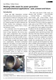
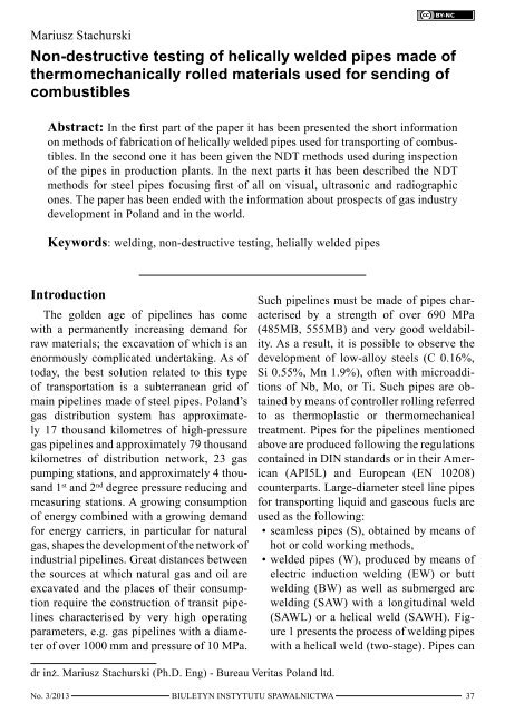
Mariusz Stachurski<strong>Non</strong>-<strong>destructive</strong> <strong>testing</strong> <strong>of</strong> <strong>helically</strong> <strong>welded</strong> <strong>pipes</strong> <strong>made</strong> <strong>of</strong>thermomechanically rolled materials used for sending <strong>of</strong>combustiblesAbstract: In the first part <strong>of</strong> the paper it has been presented the short informationon methods <strong>of</strong> fabrication <strong>of</strong> <strong>helically</strong> <strong>welded</strong> <strong>pipes</strong> used for transporting <strong>of</strong> combustibles.In the second one it has been given the NDT methods used during inspection<strong>of</strong> the <strong>pipes</strong> in production plants. In the next parts it has been described the NDTmethods for steel <strong>pipes</strong> focusing first <strong>of</strong> all on visual, ultrasonic and radiographicones. The paper has been ended with the information about prospects <strong>of</strong> gas industrydevelopment in Poland and in the world.Keywords: welding, non-<strong>destructive</strong> <strong>testing</strong>, helially <strong>welded</strong> <strong>pipes</strong>IntroductionThe golden age <strong>of</strong> pipelines has comewith a permanently increasing demand forraw materials; the excavation <strong>of</strong> which is anenormously complicated undertaking. As <strong>of</strong>today, the best solution related to this type<strong>of</strong> transportation is a subterranean grid <strong>of</strong>main pipelines <strong>made</strong> <strong>of</strong> steel <strong>pipes</strong>. Poland’sgas distribution system has approximately17 thousand kilometres <strong>of</strong> high-pressuregas pipelines and approximately 79 thousandkilometres <strong>of</strong> distribution network, 23 gaspumping stations, and approximately 4 thousand1 st and 2 nd degree pressure reducing andmeasuring stations. A growing consumption<strong>of</strong> energy combined with a growing demandfor energy carriers, in particular for naturalgas, shapes the development <strong>of</strong> the network <strong>of</strong>industrial pipelines. Great distances betweenthe sources at which natural gas and oil areexcavated and the places <strong>of</strong> their consumptionrequire the construction <strong>of</strong> transit pipelinescharacterised by very high operatingparameters, e.g. gas pipelines with a diameter<strong>of</strong> over 1000 mm and pressure <strong>of</strong> 10 MPa.Such pipelines must be <strong>made</strong> <strong>of</strong> <strong>pipes</strong> characterisedby a strength <strong>of</strong> over 690 MPa(485MB, 555MB) and very good weldability.As a result, it is possible to observe thedevelopment <strong>of</strong> low-alloy steels (C 0.16%,Si 0.55%, Mn 1.9%), <strong>of</strong>ten with microadditions<strong>of</strong> Nb, Mo, or Ti. Such <strong>pipes</strong> are obtainedby means <strong>of</strong> controller rolling referredto as thermoplastic or thermomechanicaltreatment. Pipes for the pipelines mentionedabove are produced following the regulationscontained in DIN standards or in their American(API5L) and European (EN 10208)counterparts. Large-diameter steel line <strong>pipes</strong>for transporting liquid and gaseous fuels areused as the following:• seamless <strong>pipes</strong> (S), obtained by means <strong>of</strong>hot or cold working methods,• <strong>welded</strong> <strong>pipes</strong> (W), produced by means <strong>of</strong>electric induction welding (EW) or buttwelding (BW) as well as submerged arcwelding (SAW) with a longitudinal weld(SAWL) or a helical weld (SAWH). Figure1 presents the process <strong>of</strong> welding <strong>pipes</strong>with a helical weld (two-stage). Pipes candr inż. Mariusz Stachurski (Ph.D. Eng) - Bureau Veritas Poland ltd.No. 3/2013 BIULETYN INSTYTUTU SPAWALNICTWA37
also be <strong>welded</strong> using the combination <strong>of</strong>gas-shielded welding <strong>of</strong> root runs andsubmerged arc welding <strong>of</strong> filling layers(COW) [1].First stage tack weld –MAG weldingSecond stage submerged arcwelding (with three automaticwelding machinessimultaneously)Fig. 1. Two-stage helical welding <strong>of</strong> <strong>pipes</strong> used by theGerman company <strong>of</strong> Salzgitter Mannesmann GrossrohrGmbH [5]This article presents non-<strong>destructive</strong> <strong>testing</strong><strong>of</strong> thermomechanically rolled <strong>helically</strong>submerged arc <strong>welded</strong> (SAWH) <strong>pipes</strong>L485MB and L555MB. These <strong>pipes</strong> were selectedas they are typical and manufacturedin many steelworks both in Poland and overseas.Following their manufacture the <strong>pipes</strong>undergo insulation application, usually withpolyethylene or polypropylene and are paintedinside with epoxy paints.<strong>Non</strong>-<strong>destructive</strong> <strong>testing</strong> used duringpipe manufactureGeneral informationThe basic purpose <strong>of</strong> non-<strong>destructive</strong> <strong>testing</strong>(NDT) is to assess the condition <strong>of</strong> a materialor <strong>welded</strong> joint and, on this basis, toissue an opinion related to the quality, durabilityand safe operation <strong>of</strong> a structure. Theeffectiveness and quality <strong>of</strong> non-<strong>destructive</strong><strong>testing</strong> depends on numerous factors:• personnel competence based on adequatetraining,• experience,• inspection procedures,• equipment,• environment in which <strong>testing</strong> is carried out,• psychological pressure, to which NDTpersonnel are exposed,• working time during the day,• equipment features,• supervision and how it is exercised,• applied standards, requirements andguidelines,• systems applied for the certification <strong>of</strong>personnel, procedures and equipment [1].The basic NDT methods used in the production<strong>of</strong> <strong>pipes</strong> are the following:• visual <strong>testing</strong> – VT,• radiographic <strong>testing</strong> <strong>of</strong> pipe ends – RT,• automatic fluoroscopic <strong>testing</strong> <strong>of</strong> a whole<strong>welded</strong> joint,• ultrasonic <strong>testing</strong> <strong>of</strong> a burden material inthe form <strong>of</strong> a strip unwound from a coil(laminar imperfection test) – UT,• automatic ultrasonic <strong>testing</strong> <strong>of</strong> a whole<strong>welded</strong> joint – UT,• manual ultrasonic <strong>testing</strong> <strong>of</strong> a <strong>welded</strong> jointon a pipe end – UT,• manual ultrasonic <strong>testing</strong> <strong>of</strong> a <strong>welded</strong> jointbeing repaired – UT.In addition, in order to determine preciselythe size <strong>of</strong> welding imperfections, alsoother NDT methods, i.e. penetration <strong>testing</strong>(PT) and magnetic particle <strong>testing</strong> (MT),can be used.The basic standard describing the selection<strong>of</strong> <strong>testing</strong> manners and assessment criteriais standard PN-EN 10208-2 “Steel <strong>pipes</strong>for pipelines for combustible fluids – Technicaldelivery conditions – Part 2: Pipes <strong>of</strong> requirementsclass B”. The standards describing<strong>testing</strong> manners and assessment criteriaare the following:• PN-EN 10246-9 <strong>Non</strong>-<strong>destructive</strong> <strong>testing</strong><strong>of</strong> Steel Tubes – Part 9: Automatic UltrasonicTesting <strong>of</strong> the Weld Seam <strong>of</strong> SubmergedArc Welded Steel Tubes for theDetection <strong>of</strong> Longitudinal and/or TransverseImperfections;• PN-EN 10246-10 <strong>Non</strong>-<strong>destructive</strong> <strong>testing</strong><strong>of</strong> Steel Tubes – Part 10: RadiographicTesting <strong>of</strong> <strong>of</strong> the Weld Seam <strong>of</strong> AutomaticFusion Arc Welded Steel Tubes for theDetection <strong>of</strong> Imperfections;38 BIULETYN INSTYTUTU SPAWALNICTWANo. 3/2013
• PN-EN 10246-15 <strong>Non</strong>-<strong>destructive</strong> <strong>testing</strong><strong>of</strong> Steel Tubes – Part 15: Automatic UltrasonicTesting <strong>of</strong> Strip/Plate Used in Manufacture<strong>of</strong> Welded Steel Tubes for the Detection<strong>of</strong> Laminar Imperfections;• PN-EN 10246-16 <strong>Non</strong>-<strong>destructive</strong> <strong>testing</strong><strong>of</strong> Steel Tubes – Part 16: Automatic UltrasonicTesting <strong>of</strong> the Area Adjacent to theWeld Seam <strong>of</strong> Welded Steel Tubes for theDetection <strong>of</strong> Laminar Imperfections;• PN-EN 10246-17 <strong>Non</strong>-<strong>destructive</strong> <strong>testing</strong><strong>of</strong> Steel Tubes – Part 17: Ultrasonic Testing<strong>of</strong> Tube Ends <strong>of</strong> Seamless and WeldedSteel Tubes for the Detection <strong>of</strong> LaminarImperfections;• PN-EN ISO 10893-6 <strong>Non</strong>-<strong>destructive</strong><strong>testing</strong> <strong>of</strong> Steel Tubes – Part 6: RadiographicTesting <strong>of</strong> the Weld Seam <strong>of</strong>Welded Steel Tubes for the Detection <strong>of</strong>Imperfections;• PN-EN ISO 10893-8 <strong>Non</strong>-<strong>destructive</strong> <strong>testing</strong><strong>of</strong> Steel Tubes – Part 8: Automatic UltrasonicTesting <strong>of</strong> Seamless and WeldedSteel Tubes for the Detection <strong>of</strong> LaminarImperfections;• PN-EN ISO 10893-9 <strong>Non</strong>-<strong>destructive</strong><strong>testing</strong> <strong>of</strong> Steel Tubes – Part 9: AutomatedUltrasonic Testing for the Detection <strong>of</strong>Laminar Imperfections in Strip/Plate Usedin the Manufacture <strong>of</strong> Welded Steel Tubes;Types <strong>of</strong> imperfectionsdetected during pipemanufactureResidual magnetismon pipe endsLaminar imperfectionon pipe endsLongitudinal/transverseimperfections in <strong>welded</strong>jointLaminar imperfectionson pipe bodyLaminar imperfectionson strip edge wheretransverse weld was<strong>made</strong><strong>Non</strong>-<strong>destructive</strong> <strong>testing</strong><strong>of</strong> weld in pipe ends(areas not tested previously)/ <strong>testing</strong> <strong>of</strong> areasbeing repairedTable 1. <strong>Non</strong>-<strong>destructive</strong> tests used in manufacture <strong>of</strong> <strong>pipes</strong> [2]Testing statusObligatoryOptionalObligatoryOptionalOptionalObligatoryTypes <strong>of</strong> tests, requirements and acceptance levelsGaussmeter using Hall effect or equivalent; max. 30 gausses,random testsUltrasonic <strong>testing</strong> according to PN-EN 10246-17 or PN-ENISO 10893-8, inspection area: max. 6 mm from pipe ends oncircumferenceUltrasonic <strong>testing</strong> according to EN 10246-9 or PN-EN ISO10893-11, acceptance level U2/U2H or calibration method”two lamb” (also for welds joining strip ends in <strong>helically</strong> <strong>welded</strong><strong>pipes</strong>)Radiographic <strong>testing</strong> according to PN-EN 10246-10 or PN-ENISO 10893-6, image quality class R1, used for T-type joints <strong>of</strong><strong>helically</strong> <strong>welded</strong> <strong>pipes</strong>Ultrasonic <strong>testing</strong> according to PN-EN 10246-15 or PN-ENISO 10893-9, acceptance level U2Ultrasonic <strong>testing</strong> according to PN-EN 10246-15 or PN-ENISO 10893-9 or alternatively ultrasonic <strong>testing</strong> according toPN-EN 10246-16 or PN-EN ISO 10893-8, acceptance levelU2Ultrasonic <strong>testing</strong> according to PN-EN 10246-9 or PN-EN ISO10893-11 for longitudinal imperfections, acceptance level U2/U2Hor (if not specified otherwise)Radiographic <strong>testing</strong> according to PN-EN 10246-10 orPN-EN ISO 10893-6, image quality class R1for longitudinalimperfectionsandUltrasonic <strong>testing</strong> according to PN-EN 10246-9, (PN-ENISO 10893-11) or radiographic <strong>testing</strong> according to PN-EN10246-10 (PN-EN ISO 10893-6) for transverse imperfectionsNo. 3/2013 BIULETYN INSTYTUTU SPAWALNICTWA39
• PN-EN ISO 10893-11 <strong>Non</strong>-<strong>destructive</strong> <strong>testing</strong><strong>of</strong> Steel Tubes – Part 11: Automated UltrasonicTesting <strong>of</strong> the Weld Seam <strong>of</strong> WeldedSteel Tubes for the Detection <strong>of</strong> Longitudinaland/or Transverse Imperfections.The standards <strong>of</strong> the PN-EN 10246 serieshave been now replaced by the standards<strong>of</strong> the PN-EN ISO 10893 series. The basicproduct standard PN-EN 10208-2 (version ineffect) still indicates older standards as thosein effect. As a result, all the greater productionplants continue to use these standards inthe manufacturing <strong>of</strong> <strong>pipes</strong>. For this reason,in all cases this study refers to both standardsas recommended for use. As far as ultrasonicmanual <strong>testing</strong> is concerned, the standardsapplied are the basic standards concernedwith the manner <strong>of</strong> the ultrasonic manual<strong>testing</strong> <strong>of</strong> <strong>welded</strong> joints and their assessmentand are not discussed in this study. A detailedlist <strong>of</strong> non-<strong>destructive</strong> tests applied in pipemanufacture is presented in Table 1.The residual magnetism at the ends <strong>of</strong>each pipe, parallel in relation to the pipe axis,should not exceed 30 G (3mT). The measurement<strong>of</strong> magnetism should be carried out ona random basis on the butting face <strong>of</strong> the pipeend, by means <strong>of</strong> a calibrated meter (gaussmeter)using the Hall effect or by means <strong>of</strong>equivalent devices.All non-<strong>destructive</strong> tests <strong>of</strong> <strong>welded</strong> jointsshould follow a hydraulic test <strong>of</strong> the pipe.Visual <strong>testing</strong> (VT)In accordance with the requirements <strong>of</strong>standard PN-EN 10208-2 each pipe shouldundergo a visual inspection <strong>of</strong> the entireouter surface. The inner surface <strong>of</strong> the <strong>pipes</strong>hould be inspected on each side <strong>of</strong> the pipeif its outer diameter is 610 mm or less and in100% <strong>of</strong> the entire inner surface if the outerdiameter <strong>of</strong> the pipe is 610 mm or greater.Visual <strong>testing</strong> should be carried out by adequatelytrained personnel and with properlighting <strong>of</strong> the surface being viewed (thelight intensity should amount to a minimum<strong>of</strong> 300 lx).Pipes should be free from imperfectionsas a finished product. The appearance <strong>of</strong> theouter and inner surfaces <strong>of</strong> the pipe should betypical for the production process and heattreatment applied. No surface imperfectionsrequiring removal should be visible.Below are presented manners <strong>of</strong> dealingwith imperfections detected on the outersurface:• imperfections with a depth equal to or below12.5% <strong>of</strong> a required wall thickness,which do not reduce the nominal thickness<strong>of</strong> the pipe in the place <strong>of</strong> their occurrenceshould be treated as allowed imperfections(they can remain on the pipe surface or, inaccordance with the manufacturer’s decision,can be removed by cosmetic grinding);• imperfections with a depth exceeding12.5% <strong>of</strong> a required wall thickness, whichdo not reduce the nominal thickness <strong>of</strong> thepipe in the place <strong>of</strong> their occurrence areclassified as imperfections and should beremoved by grinding (after grinding it isnecessary to apply a proper NDT method,e.g. MT, in order to check the pipe surfaceafter grinding);• imperfections which reduce the nominalthickness <strong>of</strong> the pipe in the place <strong>of</strong> theiroccurrence should be treated as unallowedimperfections and repaired by welding orthe part <strong>of</strong> the pipe containing such imperfectionsshould be cut out (the requiredlength <strong>of</strong> the time should be maintained).If the aforesaid solution is impossible,a pipe with an unallowed imperfectionshould be rejected.Geometrical deformations <strong>of</strong> the cylindricalcontour <strong>of</strong> the pipe should not exceed thefollowing:• 3 mm (flattening, metal excess, coldformedindentations with gentle edges);• 6 mm (other indentations).40 BIULETYN INSTYTUTU SPAWALNICTWANo. 3/2013
Outer imperfections can be removed only bymachining or grinding. The thickness <strong>of</strong> apipe wall in the areas being repaired cannotbe less than the required nominal wall thickness.All machined/ground areas should gentlypass into the contour <strong>of</strong> the pipe [2].Ultrasonic <strong>testing</strong> (UT)Ultrasonic <strong>testing</strong> <strong>of</strong> strip (pipe body) forlaminar imperfectionsThe first type <strong>of</strong> ultrasonic <strong>testing</strong> usedduring pipe checks is <strong>testing</strong> for laminar imperfections<strong>of</strong> the strip surface. In this caseit is possible to accept ultrasonic <strong>testing</strong> carriedout at the sheet manufacturer’s or testa (flat-formed) material used in the production<strong>of</strong> <strong>pipes</strong>, acting in accordance with therequirements <strong>of</strong> standards PN-EN 10246-15or PN-EN ISO 10893-9 and acceptance levelU2. Single laminar imperfections or laminarimperfections in groups exceeding acceptancelevel U2 are unallowed [2, 6, 11]. Anexample <strong>of</strong> a device for strip ultrasonic <strong>testing</strong>is presented in Figure 2.Fig. 2. Device applied in UT <strong>of</strong> strips for the presence<strong>of</strong> laminar imperfections, used in the Salzgitter MannesmannGrossrohr GmbH compay, Germany [5]Ultrasonic <strong>testing</strong> for the detection<strong>of</strong> longitudinal and transverse imperfectionsin <strong>welded</strong> jointsIn order to ensure full NDT <strong>of</strong> <strong>welded</strong>joints it is required that <strong>helically</strong> <strong>welded</strong><strong>pipes</strong> should undergo ultrasonic <strong>testing</strong>along their whole length. The test objectiveincludes both longitudinal and transverse imperfections.Ultrasonic <strong>testing</strong> should be carriedout in accordance with the requirements<strong>of</strong> standard PN-EN 10246-9 or PN-EN ISO10893-11 [2]. As a rule, UT <strong>of</strong> <strong>pipes</strong> followsthe completion <strong>of</strong> all the main operations <strong>of</strong>a production process. In order to ensure thereliability <strong>of</strong> ultrasonic <strong>testing</strong>, <strong>pipes</strong> shouldbe sufficiently straight and free from foreignmatter.In order to detect longitudinal and transverseimperfections, helical welds shouldundergo ultrasonic <strong>testing</strong>. In both cases the<strong>testing</strong> should be conducted in two oppositebeam propagation directions. During thetest the converter unit should remain in theproper position in relation to a weld so thatthe entire weld could be searched through. Asearching rate should not oscillate by morethan 10% than the adopted basic rate. Dependingon the thickness and roughness <strong>of</strong>the pipe surface, the frequency used in UTshould be contained within a 1 MHz÷15 MHzrange. The maximum width <strong>of</strong> each singleconverter, measured parallel to the mainaxis <strong>of</strong> the pipe, should amount to 25 mm.By means <strong>of</strong> an ultrasonic monitor connectedwith a marking and/or sorting system, theequipment should enable the classification <strong>of</strong><strong>pipes</strong> as accepted or rejected. If it is not possibleto test welds on pipe ends by means <strong>of</strong>automatic ultrasonic <strong>testing</strong> equipment, the<strong>testing</strong> <strong>of</strong> pipe ends should be conducted bythe manufacturer using either manual ultrasonic<strong>testing</strong> or radiographic <strong>testing</strong>.Ultrasonic equipment for detecting longitudinalimperfections should be calibratedby means <strong>of</strong> four longitudinal grooves,No. 3/2013 BIULETYN INSTYTUTU SPAWALNICTWA41
two on the outer surface and two in the innersurface <strong>of</strong> pipe masters and/or by means <strong>of</strong>a datum hole (Fig. 3). Converters used fordetecting transverse imperfections shouldbe calibrated by means <strong>of</strong> a hole and/or twogrooves transverse in relation to the weld,one on the outside and one inside a samplebeing tested. The decision whether to choosegrooves or a hole is at the manufacturer’sdiscretion.A reference groove should be <strong>of</strong> an”N-type” (Fig. 4). The sides <strong>of</strong> the grooveshould be parallel to each other and the bottomshould be perpendicular to the sides.Fig. 4. “N-groove” [3, 9].w – width, d - depthFig. 3. Arrangement <strong>of</strong> reference grooves and datum hole [3, 9]1. longitudinal outer grooves2. submerged arc <strong>made</strong> weld3. pipe master or pipe section4. right-through hole5. longitudinal inner groovesA test sample should have the same nominaldiameter, wall thickness, surface roughness,heat treatment state and similar acousticproperties (e.g. wave propagation velocityand wave damping coefficient) as the pipebeing tested. The manufacturer should havethe possibility <strong>of</strong> removing the inner and outerweld run in accordance with the pipe curvature.The outer and inner grooves as wellas the datum hole should be sufficiently distantfrom the pipe ends and from each otherso that clearly separate indications <strong>of</strong> signalscoming from the grooves and the hole can beobtained.Longitudinal reference grooves should belocated in the parent metal near the edge <strong>of</strong> theweld and in parallel to the weld run (Fig. 3).A reference groove should be electrodischargemachined or <strong>made</strong> with another method.The dimensions <strong>of</strong> reference groovesshould be the following:a) width, w, (Fig. 4) <strong>of</strong> a reference grooveshould not exceed 1.5 mm;b) depth, d, (Fig. 4) should be as specified inTable 2, subject to the following restrictions:◦◦minimum groove depth: 0.3 mm for<strong>pipes</strong> <strong>of</strong> categories U2 and U3 and 0.5mm for <strong>pipes</strong> <strong>of</strong> category U4;◦◦maximum groove depth: 2.0 mm for<strong>pipes</strong> <strong>of</strong> categories U2 and U3 and 3mm for <strong>pipes</strong> <strong>of</strong> category U4;c) depth tolerance for a reference grooveshould amount to ± 15% depth or ± 0.05mm, whichever value is greater;d) length <strong>of</strong> reference grooves should beequal to at least double width <strong>of</strong> each singleconverter, but not more than 50 mm.A datum hole should be drilled through thewall <strong>of</strong> a test sample, in the weld centre, perpendicularlyto the sample surface (Fig. 3).42 BIULETYN INSTYTUTU SPAWALNICTWANo. 3/2013
The diameter <strong>of</strong> the drill used to make the datumhole should be selected in accordance withTable 3. The diameter <strong>of</strong> a datum hole shouldbe checked and cannot exceed the nominal diameter<strong>of</strong> a drill by more than 0.2 mm.Table 2. Designation <strong>of</strong> acceptance level and relateddepth <strong>of</strong> reference groove [3, 9]AcceptancelevelGroove depth in % <strong>of</strong> nominalwall thicknessU2 5.0U3 10.0U4 12.5U5 15.0<strong>testing</strong> sensitivity by 3 dB (to compensateequipment indications), it is necessary tocarry out equipment calibration again aswell as to check all the <strong>pipes</strong> tested since theprevious calibration verification.Table 3. Designation <strong>of</strong> acceptance level and relateddrill diameter [3, 9]AcceptancelevelDrill diameterU2H 1.6U3H 3.2U4H 4.0The equipment should be calibrated sothat it would ensure (e.g. in three subsequentpasses <strong>of</strong> the test sample through the equipment)obtaining clearly distinguishable signals<strong>of</strong> the reference standard. The peak value<strong>of</strong> the amplitude <strong>of</strong> these signals shouldbe used for adjusting the level <strong>of</strong> the gate/alarm monitor in the equipment. The rate<strong>of</strong> the test sample travel in relation to theset <strong>of</strong> ultrasonic converters during the verification<strong>of</strong> calibration should be the sameas during the tests <strong>of</strong> a product. Calibrationcan be verified by means <strong>of</strong> a semi-dynamicmethod. During the <strong>testing</strong> <strong>of</strong> <strong>pipes</strong> with thesame nominal diameter, wall thickness, and<strong>made</strong> <strong>of</strong> the same steel grade, it is necessaryto verify the calibration <strong>of</strong> the equipmentat regular intervals. The equipment calibrationis verified by putting the pipe masterthrough the <strong>testing</strong> equipment. The verification<strong>of</strong> calibration should be carried out atleast once every four hours as well as eachtime the equipment operator changes. Calibrationshould also be verified at the beginningand end <strong>of</strong> production. In addition, theequipment should be calibrated if any <strong>of</strong> theparameters set during the initial calibrationhave been altered. If while verifying calibrationduring production, calibration requirementsare not satisfied even after increasingFollowing <strong>testing</strong>, a pipe revealing signalsbelow the monitor/gate sensitivity thresholdshould be classified as meeting the requirements.And a pipe having signals equal toor greater than the monitor/gate sensitivitythreshold should be classified as questionedor, at the manufacturer’s request, shouldundergo another test. If during the subsequenttest <strong>of</strong> the same pipe no signal equalto or greater than the monitor/gate sensitivitythreshold was obtained, the pipe shouldbe regarded as meeting the requirements.Depending on the requirements <strong>of</strong> a productstandard, <strong>pipes</strong> questioned during <strong>testing</strong>should be dealt with in accordance with oneor several following manners:a) Subject to an agreement between the purchaserand the manufacturer, the areawhich has been questioned should be testedby means <strong>of</strong> another NDT technique ormethod (usually radiographic), on the basis<strong>of</strong> agreed acceptance criteria;b) The questioned area should be cut out. Themanufacturer should guarantee that thewhole questioned area has been removed;c) The pipe should be classified as not satisfyingthe requirements [3, 9].Testing <strong>of</strong> <strong>helically</strong> <strong>welded</strong> <strong>pipes</strong> is carriedout for acceptance level U2/U2H, taking intoaccount the following inspection criteria:No. 3/2013 BIULETYN INSTYTUTU SPAWALNICTWA43
a) the maximum groove depth should amountto 2.0 mm;b) Using inner and outer longitudinalgrooves in the middle <strong>of</strong> the weld run forthe purpose <strong>of</strong> equipment calibration isunallowed;c) In the case <strong>of</strong> acceptance level U2, for thepurpose <strong>of</strong> detecting transverse imperfections,as an alternative to the datum holeone may use the inner and outer groovespositioned at a right angle and centredin the weld. In such a situation both innerand outer weld reinforcements shouldbe ground evenly with the pipe contour,in the direct vicinity and on both sides <strong>of</strong>reference grooves. The grooves should besufficiently distant from each other in alongitudinal direction. They should alsobe sufficiently distant from any other reinforcements.Such an approach is necessaryto obtain a clear and distinguishableultrasonic signal response. In order to determinethe level <strong>of</strong> the gate/alarm <strong>of</strong> themeasuring equipment it is necessary to usethe complete amplitude <strong>of</strong> a signal fromeach <strong>of</strong> these grooves.d) For acceptance level U2 and by prioragreement, as an alternative to using referencegrooves for calibration purposes, itis possible to use inner and outer grooves<strong>of</strong> a constant depth and increase <strong>testing</strong>sensitivity using electronic methods (byincreasing dB amplification). In this case,also referred to as the „two lamb method”,the depth <strong>of</strong> grooves should be twice asbig as the length <strong>of</strong> an ultrasonic wave.A required increase in <strong>testing</strong> sensitivityshould depend on a pipe wall thickness. Themanufacturer should adequately assure thepurchaser that obtained <strong>testing</strong> sensitivity isbasically equivalent to that obtained whileusing grooves for acceptance level U2. Inthe case <strong>of</strong> <strong>helically</strong> <strong>welded</strong> <strong>pipes</strong> the entirelength <strong>of</strong> the weld joining strip edges shouldalso undergo ultrasonic <strong>testing</strong>. Testing sensitivityand parameters should be the same asduring the initial <strong>testing</strong> <strong>of</strong> the pipe helicalweld. In addition, cruciform joints, in whichthe weld ends <strong>of</strong> strip edges meet the helicalweld should undergo radiographic <strong>testing</strong> [2].Following the tests, the manufacturershould provide the ordering party with a reportcontaining at least the following information:a) reference to standards PN-EN 10246-9 orPN-EN ISO 10893-11 andPN-EN 10208-2;b) date <strong>of</strong> test report;c) acceptance level;d) declaration <strong>of</strong> conformity;e) product specification, i.e. steel grade anddimensions;f) type and details <strong>of</strong> <strong>testing</strong> technique;g) description <strong>of</strong> a master/standard [3, 9].An example <strong>of</strong> a device for UT <strong>of</strong> <strong>helically</strong><strong>welded</strong> <strong>pipes</strong> is presented in Figure 5.Fig. 5. Automatic multichannel device for ultrasonic<strong>testing</strong> <strong>of</strong> <strong>helically</strong> <strong>welded</strong> pipe weld and strip-joiningweld used in the Salzgitter Mannesmann GrossrohrGmbH company, Germany[5]Laminar imperfections in strip area adjacentto <strong>welded</strong> jointIn such a case it is possible to accept ultrasonic<strong>testing</strong> carried out at steel sheet manufacturer’sor carry out post-weld <strong>testing</strong> atthe pipe manufacturer’s, following the requirements<strong>of</strong> standard PN-EN 10246-16 orPN-EN ISO 10893-8 and acceptance level44 BIULETYN INSTYTUTU SPAWALNICTWANo. 3/2013
U2. The tests are conducted within a 15mmwidezone along both longitudinal edges <strong>of</strong> ahelical weld. In the case <strong>of</strong> transverse weldsjoining the edge <strong>of</strong> a strip <strong>testing</strong> is conductedalong areas adjacent to this butt weld. Requirementsconcerned with ultrasonic <strong>testing</strong><strong>of</strong> laminar imperfections in the area adjacentto the weld are dealt with in standard PN-EN 10246-15 (PN-EN ISO 10893-9) or PN-EN 10246-16 (PN-EN ISO 10893-8). Singlelaminar imperfections or imperfections ingroups exceeding acceptance level U2 arenot allowed [2].<strong>Non</strong>-<strong>destructive</strong> <strong>testing</strong> <strong>of</strong> <strong>helically</strong> <strong>welded</strong>joints on pipe ends and in areas beingrepairedSections <strong>of</strong> <strong>welded</strong> joints on pipe endswhich cannot be tested by means <strong>of</strong> automaticultrasonic equipment and repaired areas <strong>of</strong>welds should undergo the following tests:a) in order to detect longitudinal imperfections– manual or semiautomatic ultrasonic<strong>testing</strong> using the same <strong>testing</strong> parametersand sensitivity as in the case <strong>of</strong> the automatic<strong>testing</strong> <strong>of</strong> the whole helical weld.Radiographic <strong>testing</strong> is also possible.b) in order to detect transverse imperfections– manual or semiautomatic ultrasonic <strong>testing</strong>using the same <strong>testing</strong> parameters andsensitivity as in the case <strong>of</strong> the automatic<strong>testing</strong> <strong>of</strong> the whole helical weld. Radiographic<strong>testing</strong> is also possible.c) It is also necessary to carry out <strong>testing</strong>for the laminar imperfections <strong>of</strong> the pipebody areas on pipe ends which cannot bechecked by means <strong>of</strong> automatic ultrasonicequipment. In such a case it is also possibleto carry out manual ultrasonic <strong>testing</strong>using the same <strong>testing</strong> parameters andsensitivity as those used while <strong>testing</strong> areasadjacent to the weld. Laminar imperfectionswith a length ≥ 6 mm occurringin girth direction are unallowed if they arepresent 25 mm away from each pipe end;d) While carrying out manual ultrasonic<strong>testing</strong> a scanning rate should not exceed150 mm/s [2].Radiographic and radioscopic <strong>testing</strong>(RT)Another <strong>testing</strong> method used in the manufacture<strong>of</strong> <strong>helically</strong> <strong>welded</strong> <strong>pipes</strong> is radiographic<strong>testing</strong>, usually carried out on <strong>pipes</strong>after the completion <strong>of</strong> all principal productionoperations. In order to ensure an appropriate<strong>testing</strong> class, <strong>pipes</strong> intended for testsshould be sufficiently straight and free fromforeign matter impurities. The surfaces <strong>of</strong>welds and adjacent parent metal should befree from foreign matter and surface imperfectionsas they could impede the interpretation<strong>of</strong> radiograms. Grinding surfaces isallowed if it can ensure obtaining a surfacecondition acceptable for tests. If a weld reinforcementmust be removed, it is advisableto place markers (usually lead arrows) inorder to identify the weld location in a radiogram.In order to ensure the unambiguousidentification <strong>of</strong> a given weld section, eachsection should be provided with identificationsymbols (usually lead letters) so thattheir images can be visible in a radiogram.It is necessary to apply permanent markingon the pipe surface from the side <strong>of</strong> the radiationsource. This is done in order to providereference points for the accurate assignment<strong>of</strong> each radiogram location. If it is impossibleto strike markers due to the type <strong>of</strong> aproduct and/or its intended operating conditions,it is necessary to provide other appropriatemeans <strong>of</strong> radiogram assignment, e.g.by marking with paint or preparing accuratesketches. In order to ensure that each part <strong>of</strong>the weld undergoes <strong>testing</strong>, during X-rayinga longer weld section with several films itis necessary that neighbouring films shouldoverlap over a minimum length <strong>of</strong> 10 mm.Longitudinal or helical welds <strong>of</strong> <strong>pipes</strong>should undergo radiographic <strong>testing</strong> withNo. 3/2013 BIULETYN INSTYTUTU SPAWALNICTWA45
x-rays. The use <strong>of</strong> radioscopic methods is allowed(Fig. 6), yet only in cases when themanufacturer can demonstrate their appropriatesensitivity.Fig. 6. Example <strong>of</strong> device for radioscopic <strong>testing</strong><strong>of</strong> <strong>welded</strong> jointsThere are two image quality classes, i.e.R1 and R2:• class R1 (class B): radiographic <strong>testing</strong>technique by means <strong>of</strong> X-radiation <strong>of</strong>heightened sensitivity;• class R2 (class A): radiographic <strong>testing</strong>technique by means <strong>of</strong> X-radiation <strong>of</strong> normalsensitivity.For image quality class R1 it is necessaryto use at least fine-grained films (at least C4class), whereas for image quality class R2one should use at least medium-grained films(at least C5 class). For both image qualityclasses (R1 and R2), the thickness <strong>of</strong> frontintensifying screens should be between 0.02mm and 0.25 mm. Rear intensifying screenscan have other thicknesses. Fluorescent intensifyingscreens should not be used.The amount <strong>of</strong> backscattered and internalX-radiation should be limited to a minimum.When in doubt as to the efficiency <strong>of</strong> protectionagainst backscattered radiation, it is advisableto fix a characteristic sign (usually a1.5mm-thick letter B) behind the film holderor film frame and make a radiogram in a normalmanner. The density <strong>of</strong> the symbol imagein the radiogram lower than the backgrounddensity indicates that the protection againstbackscattered radiation is insufficient and thatadditional precautions should be used. A radiationbeam should be directed onto the centre<strong>of</strong> a weld section being tested and should beperpendicular to the pipe surface at this point.A length subjected to an assessment should beso that the thickness X-rayed at the ends <strong>of</strong> theusable length <strong>of</strong> a radiogram does not exceedthe thickness X-rayed in the radiogram centreby more than 10% for image quality classR1 and by more than 20% for image qualityclass R2. It is necessary to use a technique <strong>of</strong>X-raying through one wall. If, due to the size<strong>of</strong> the object, such a technique cannot be used,it is allowed to use a technique <strong>of</strong> X-rayingthrough two walls (by prior agreement). Thedistance between the film and the weld surfaceshould be as small as possible.The minimum distance between the sourceand the sample ,f, should be selected usingappropriate formulas or diagrams. The conditions<strong>of</strong> exposition should be so that thedensity <strong>of</strong> a radiogram in the tested area <strong>of</strong>weld material free from imperfections is notlower than 2.0 for image quality class R1 (2.3for image quality class B) and not lower than1.7 for image quality class R2 (2.0 for imagequality class B).The quality <strong>of</strong> an image should be determinedusing an image quality indicator (IQI)<strong>made</strong> <strong>of</strong> mild steel, grade specified in standardsPN-EN 462-1 (PN-ISO 19232-1) and PN-EN 462-2 (PN-ISO 19232-2). An IQI shouldbe placed on the surface from the radiationsource side or next to the weld or, in the case<strong>of</strong> a wire-type IQI – across the weld. Imagequality indicators should be placed from thefilm side only if the surface from the sourceside is inaccessible. In such cases it is necessaryto place a letter “F” next to an IQI andmake a note <strong>of</strong> this change <strong>of</strong> the procedure inthe test report [4, 10].46 BIULETYN INSTYTUTU SPAWALNICTWANo. 3/2013
sified as questioned. Questioned <strong>pipes</strong> shouldbe dealt with in one <strong>of</strong> the following manners:a) A questioned area should be levelled bymeans <strong>of</strong> an appropriate method. In orderto ensure that the imperfection has beenremoved entirely, after checking that theremaining thickness is still within a tolerancerange, the area should undergo anothercheck using magnetic particle <strong>testing</strong> orpenetration <strong>testing</strong>. Afterwards, the <strong>pipes</strong>hould be classified as passing the test. Ifthe recommended removal <strong>of</strong> the faultyarea has decreased the thickness belowthe acceptable value, the questioned areashould be repaired by welding carried outin accordance with an approved weldingprocedure specification. After that, the repairedarea should undergo radiographic<strong>testing</strong> following the requirements <strong>of</strong> PN-EN 10246-10 or PN-EN ISO 10893-6;b) A questioned area should be cut out. Themanufacturer should ensure that the wholequestioned section has been cut out;c) A pipe should be classified as failing tomeet the requirements.In required cases the manufacturer shouldwrite a test report containing at least the followinginformation:a) reference to PN-EN 10246-10 or PN-ENISO 10893-6 and PN-EN 10208-2;b) test report date;c) declaration <strong>of</strong> conformity;d) designation <strong>of</strong> a product providing gradeand dimensions;e) type <strong>of</strong> and detailed information about the<strong>testing</strong> technique used;f) each deviation from specified procedures,agreed or not agreed;g) image quality class;h) operator’s name, signature and certificatenumber [4, 10].ConclusionIn recent years the manufacture <strong>of</strong> <strong>helically</strong><strong>welded</strong> <strong>pipes</strong> has seen an intensive developmentowing to new gas pipelines underconstruction both in Poland and abroad. Theproduction <strong>of</strong> these <strong>pipes</strong> requires the use <strong>of</strong>materials characterised by the highest mechanicalproperties in a given material group.NDT devices are usually provided with modernand recently developed technical solutions.Investment-related expectations forthe years to come make the manufacture <strong>of</strong><strong>welded</strong> <strong>pipes</strong> the area <strong>of</strong> interest for investorsand manufacturers all over the world.References1. Michałowski, W., and Trzop, S., et al.(2006). Rurociągi dalekiego zasięgu. Warsaw:Wydawnictwo Fundacja Odysseum.2. PN-EN 10208-2:2011 Steel <strong>pipes</strong> forpipelines for combustible fluids - Technicaldelivery conditions - Part 2: Pipes <strong>of</strong>requirement class B3. PN-EN 10246-9:2004 <strong>Non</strong>-<strong>destructive</strong><strong>testing</strong> <strong>of</strong> steel tubes - Part 9: Automaticultrasonic <strong>testing</strong> <strong>of</strong> the weld seam <strong>of</strong>submerged arc <strong>welded</strong> steel tubes for thedetection <strong>of</strong> longitudinal and/or transverseimperfections4. PN-EN 10246-10:2004 <strong>Non</strong>-<strong>destructive</strong><strong>testing</strong> <strong>of</strong> steel tubes - Part 10: Radiographic<strong>testing</strong> <strong>of</strong> the weld seam <strong>of</strong> automaticfusion arc <strong>welded</strong> steel tubes forthe detection <strong>of</strong> imperfections5. Presentation <strong>of</strong> Salzgitter MannesmannGrossrohr GmBH - Salzgitter 2012.6. PN-EN 10246-15:2002 <strong>Non</strong>-<strong>destructive</strong><strong>testing</strong> <strong>of</strong> steel tubes - Part 15: Automaticultrasonic <strong>testing</strong> <strong>of</strong> strip/plate used inthe manufacture <strong>of</strong> <strong>welded</strong> steel tubes forthe detection <strong>of</strong> laminar imperfections7. PN-EN 10246-16:2002 <strong>Non</strong>-<strong>destructive</strong><strong>testing</strong> <strong>of</strong> steel tubes - Part 16: Automaticultrasonic <strong>testing</strong> <strong>of</strong> the area adjacent tothe weld seam <strong>of</strong> <strong>welded</strong> steel tubes forthe detection <strong>of</strong> laminar imperfections8. PN-EN 10246-17:2002 <strong>Non</strong>-<strong>destructive</strong><strong>testing</strong> <strong>of</strong> steel tubes - Part 17: Ultrason-48 BIULETYN INSTYTUTU SPAWALNICTWANo. 3/2013
ic <strong>testing</strong> <strong>of</strong> tube ends <strong>of</strong> seamless and<strong>welded</strong> steel tubes for the detection <strong>of</strong>laminar imperfections9. PN-EN ISO 10893-6:2011 <strong>Non</strong>-<strong>destructive</strong><strong>testing</strong> <strong>of</strong> steel tubes - Part 6: Radiographic<strong>testing</strong> <strong>of</strong> the weld seam <strong>of</strong><strong>welded</strong> steel tubes for the detection <strong>of</strong>imperfections10. PN-EN ISO 10893-8:2011 <strong>Non</strong>-<strong>destructive</strong><strong>testing</strong> <strong>of</strong> steel tubes - Part 8: Automatedultrasonic <strong>testing</strong> <strong>of</strong> seamless and<strong>welded</strong> steel tubes for the detection <strong>of</strong>laminar imperfections11. PN-EN ISO 10893-9:2011 <strong>Non</strong>-<strong>destructive</strong><strong>testing</strong> <strong>of</strong> steel tubes - Part 9: Automatedultrasonic <strong>testing</strong> for the detection<strong>of</strong> laminar imperfections in strip/plateused for the manufacture <strong>of</strong> <strong>welded</strong> steeltubes12. PN-EN ISO 10893-11:2011 <strong>Non</strong>-<strong>destructive</strong><strong>testing</strong> <strong>of</strong> steel tubes - Part 11: Automatedultrasonic <strong>testing</strong> <strong>of</strong> the weld seam<strong>of</strong> <strong>welded</strong> steel tubes for the detection <strong>of</strong>longitudinal and/or transverse imperfectionsNo. 3/2013 BIULETYN INSTYTUTU SPAWALNICTWA49