MRC-312-6 - Snap-on Equipment
MRC-312-6 - Snap-on Equipment
MRC-312-6 - Snap-on Equipment
You also want an ePaper? Increase the reach of your titles
YUMPU automatically turns print PDFs into web optimized ePapers that Google loves.
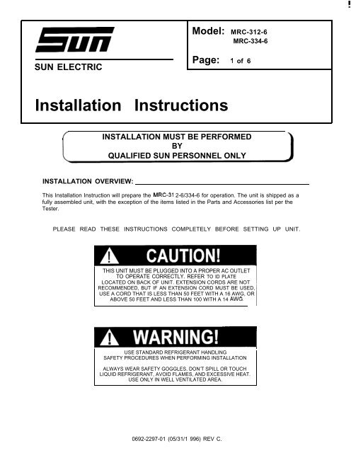
mSUN ELECTRICModel: <str<strong>on</strong>g>MRC</str<strong>on</strong>g>-<str<strong>on</strong>g>312</str<strong>on</strong>g>-6<str<strong>on</strong>g>MRC</str<strong>on</strong>g>-334-6Page: 1 of 6Installati<strong>on</strong> Instructi<strong>on</strong>s( INSTALLATION MUST BE PERFORMEDBYQUALIFIED SUN PERSONNEL ONLYINSTALLATION OVERVIEW:This Installati<strong>on</strong> Instructi<strong>on</strong> will prepare the <str<strong>on</strong>g>MRC</str<strong>on</strong>g>-31 2-6/334-6 for operati<strong>on</strong>. The unit is shipped as afully assembled unit, with the excepti<strong>on</strong> of the items listed in the Parts and Accessories list per theTester.PLEASE READ THESE INSTRUCTIONS COMPLETELY BEFORE SETTING UP UNIT.THIS UNIT MUST BE PLUGGED INTO A PROPER AC OUTLETTO OPERATE CORRECTLY. REFER TO ID PLATELOCATED ON BACK OF UNIT. EXTENSION CORDS ARE NOTRECOMMENDED, BUT IF AN EXTENSION CORD MUST BE USED,USE A CORD THAT IS LESS THAN 50 FEET WITH A 16 AWG, ORABOVE 50 FEET AND LESS THAN 100 WITH A 14 AWG.USE STANDARD REFRIGERANT HANDLINGSAFETY PROCEDURES WHEN PERFORMING INSTALLATIONALWAYS WEAR SAFETY GOGGLES, DON’T SPILL OR TOUCHLIQUID REFRIGERANT, AVOID FLAMES, AND EXCESSIVE HEAT.USE ONLY IN WELL VENTILATED AREA.0692-2297-01 (05/31/1 996) REV C.
Page 2 of 6PARTS AND ACCESSORIES FOR <str<strong>on</strong>g>MRC</str<strong>on</strong>g>-<str<strong>on</strong>g>312</str<strong>on</strong>g>-6:PART NUMBER0119-0354-010403-1541-080647-0196-010647-0197-010647-0199-010647-0200-010671-1026-010675-04230692-2297-014211-0001-017009-2417-017012-1369-017012-1537-01EAHOO13C22ADESCRIPTIONLiterature Kit, <str<strong>on</strong>g>MRC</str<strong>on</strong>g>-31 2-6Screw #1 O-32x 1/2” (May be Installed)Adapter, GMAdapter, Quick-Disc<strong>on</strong>nect, GM/FordAdapter, Quick-Disc<strong>on</strong>nect, Large, GMAdapter, FordDesiccant BagScrew 1/4-20 x 3/8”Installati<strong>on</strong> Instructi<strong>on</strong>sEnvelopeInline Patticle FilterBracket, HoseBracket, GaugeGauge Set, UniweldQTY121111102112111PARTS AND ACCESSORIES FOR <str<strong>on</strong>g>MRC</str<strong>on</strong>g>-334-6:PART NUMBER0119-0353-010403-1541-080671-1018-020675-04230692-2297-014211-0001-017009-2418-017012-1369-017012-1537-01EAHO014COOADESCRIPTIONLiterature Kit, <str<strong>on</strong>g>MRC</str<strong>on</strong>g>-334-6Screw #1 O-32x 1 /2” (Maybe Installed)Desiccant BagScrew 1/4-20 x 3/8”Installati<strong>on</strong> Instructi<strong>on</strong>sEnvelopeInline Particle FilterBracket, HoseBracket, GaugeGauge Set, UniweldQTY12102112111REQUIRED TOOLS:. Screwdriver (Flat Blade& Phillips). Safety Goggles (0001-5005). Refrigerant Oil (Mineral)0692-2297-01 (05/31/1 996) REV C.
UNPACKING UNIT AND ACCESSORIES:Page 3 of 61. Cut Straps, and slide the cart<strong>on</strong> off the pallet.2. Remove the top of the cart<strong>on</strong>, 4 corner posts and plastic bag. Split the corners of the basecart<strong>on</strong>.3. Lean the unit so it can be rolled off the base.4. Remove all boxes and packing material from scale/tank compartment.5. Inventory all items using the Parts & Accessories list and inspect for damage.PARTS & ACCESSORIES SETUP:1.2.3.4.5.6.7.8.9.Mount the Hose Bracket (701 2-1 369-01) to the center of the rear panel using the two Screws(0675-0423) (1/4-20 x 3/8”) supplied.Mount the Gauge Set Bracket (701 2-1 537-01) to the top center of the rear panel using the twoScrews (0403-1 541 -08) (#1 O-32x 1/2”) supplied.Remove the Gauge Set Assembly (EAHOO13C22A or EAHO014COOA) from the gauge set boxand place <strong>on</strong> Gauge Set Bracket.Remove the Blue and Red Hoses from the gauge setbox and ~ the seals <strong>on</strong> each end.C<strong>on</strong>nect the open end of the Blue and Red Hoses to the Gauge Set respectively.For the <str<strong>on</strong>g>MRC</str<strong>on</strong>g>-<str<strong>on</strong>g>312</str<strong>on</strong>g>-6, place the four adapters in the Storage Compartment <strong>on</strong> top of unit.For the <str<strong>on</strong>g>MRC</str<strong>on</strong>g>-334-6, c<strong>on</strong>nect the Red and Blue adapters (supplied in Gauge Set box) to the Redand Blue Hoses from the Gauge Set respectfully.Place the Desiccant bags (0671-1 026-01 or 0671-1018-02) in the Storage Compartment <strong>on</strong> topof unit.Remove the User% Manual from the Literature Kit, and place the remainder of the Literature Kit(01 19-0353-01 orol 19-0354-01) in the Storage Compartment <strong>on</strong> top of unit.BE SURE TO REVIEW THE USER’S MANUAL WITH THE CUSTOMER DURING TRAINING.Then before installing the User’s Manual Envelope, ask where the customer would likethe envelo~e installed.10.11.12.13.Peel the backing from the User’s Manual Envelope (421 1-0001-01) and apply the envelope, withthe open end <strong>on</strong> top, to either side of the unit or in the locati<strong>on</strong> designated by the customer.Place the User’s Manual in the Envelope.Remove Cap from Service Port <strong>on</strong> fr<strong>on</strong>t of unit. ~ the seal <strong>on</strong> the Inline Particle Filter andattach to the setvice port <strong>on</strong> fr<strong>on</strong>t of unit. (SEE USER’S MANUAL)Retrieve the Recovery Tank (not supplied with unit). ~ the seal <strong>on</strong> the Inline Particle Filterand attach to the BLUE side of Recovefy Tank.PREPARING NEW RECOVERY TANK:1. Open BLUE valve <strong>on</strong> Recovery Tank to release ALL COMPRESSED AIR.2. Remove the Yellow Hose from the gauge set box. ~ the seals <strong>on</strong> each end of hose.0692-2297-01 (05/31/1 996) REV C.
Page 4 of 63. Attach open end of Yellow Hose to BLUE valve of Recovery Tank. Attach other end of YellowHose to service port <strong>on</strong> fr<strong>on</strong>t of unit.THIS UNIT MUST BE PLUGGED INTO A PROPER AC OUTLETTO OPERATE CORRECTLY. REFER TO ID PLATELOCATED ON BACK OF UNIT. EXTENSION CORDS ARE NOTRECOMMENDED, BUT IF AN EXTENSION CORD MUST BE USED,USE A CORD THAT IS LESS THAN 50 FEET WITH A 16 AWG, ORABOVE 50 FEET AND LESS THAN 100 WITH A 14 AWG.I 14. Plug AC Cord to a proper AC outlet according to the serial plate. Turn unit <strong>on</strong> using the fr<strong>on</strong>tpower switch.5. Press and program a 10 minute vacuum time by pressing cUP> twice andthen pressing 5 times. (This programs O for remainingparameters.)6. Once completed close Recovery Tank valve (BLUE) and remove Yellow Hose from RecoveryTank.7. Re-OIL seal <strong>on</strong> Yellow Hose and c<strong>on</strong>nect to center port <strong>on</strong> Gauge Set.8. Place Recoveiy Tank <strong>on</strong> scale. Tank fittings should face straight out the back of unit. C<strong>on</strong>nectvelcro strap and tighten belt.9. Remove bubble wrap from Red and Blue Hoses <strong>on</strong> unit.10. ~ seals <strong>on</strong> the anti-blow back valves <strong>on</strong> Red and Blue Hoses from unit. C<strong>on</strong>nect respectivelyto Recovery Tank.PARAMETER SETUP:1. Press cAMOUNT> twice to display amount of refrigerant in Recovery Tank. If amount is morethan 3 ounces in an empty tank, perform sequence A through C:Press and at the same time while the amountof refrigerant is being displayed.Press and to change the amount of refrigerant to 1 oz. or until it togglesbetween O and 1 z.Press cHOLD/ENTER/RESTART> to return to normal operati<strong>on</strong>s.2. Press and hold cUP> and for 5 sec<strong>on</strong>ds. Refrigerant charge type will be displayed.3. If the display shows the incorrect type of refrigerant that is going to be dedicated for this unit,stop and call service.4. Press cUP> or to change CHARGE parameters to “LbOz”, “kg”, “Lb”, or “OZ”. Press to save the desired CHARGE parameters.5. Press or to change AMOUNT parameters to “LbOz”, or “kg”. PresscHOLD/ENTER/RESTART> to save the desired AMOUNT parameters.0692-2297-01 (05/31/1 996) REV C.
CALIBRATION:Page 5 of 61. Close both valves <strong>on</strong> Recovety Tank.2. Press and hold cHOLD/ENTER/RESTART> for 5 sec<strong>on</strong>ds until LCD displays “CAL”. Tank ic<strong>on</strong>should be flashing.3. Press cHOLD/ENTER/RESTART> again to start calibrati<strong>on</strong>. “In Progress” will be displayed.This will take 2-3 minutes to complete.4. Up<strong>on</strong> completi<strong>on</strong> of calibrati<strong>on</strong>, the temperature will be displayed. Press twice.CHARGING RECOVERY TANK:NOTE:THIS PROCEDURE IS USED TO SETUP THE UNIT FOR CHARGING.RECOVERY TANK SHOULD HAVE AT LEASTA 25” VACUUM.1.2.3.4.5.Be sure Recovery Tank valves are closed.Disc<strong>on</strong>nect the Red and Blue hoses from the Recovery Tank.Disc<strong>on</strong>nect and Re-OIL both seals <strong>on</strong> Yellow hose. C<strong>on</strong>nect the Yellow Hose with the open endto a Virgin Tank.C<strong>on</strong>nect the other end of Yellow Hose to the Red Valve <strong>on</strong> the Recovery Tank.Open the Red valve <strong>on</strong> the Recovery Tank.USE STANDARD REFRIGERANT HANDLINGSAFETY PROCEDURES WHEN PERFORMING INSTALLATIONALWAYS WEAR SAFETY GOGGLES, DON’T SPILL OR TOUCHLIQUID REFRIGERANT, AVOID FLAMES, AND EXCESSIVE HEAT.USE ONLY IN WELL VENTILATED AREA.6.7.8.9.10.11.12.Invert the Vkgin Tank and open valve. If a Hand Valve is present <strong>on</strong> the Yellow hose, open toallow the refrigerant to flow.Raise the Virgin Tank to a higher level than the Recovery Tank. Gravity and vacuum willtransfer the liquid refrigerant to the Recovery Tank faster than reclaiming it.Press cAMOUNT> twice to display the amount of refrigerant that has been transferred.After the desired amount of refrigerant has been transferred, close valves <strong>on</strong> Virgin Tank andRecovery Tank. Set Virgin Tank <strong>on</strong> ground upright.Close Hand Valve <strong>on</strong> Yellow Hose if present. Disc<strong>on</strong>nect Yellow Hose from Recovery Tank.Re-OIL seals <strong>on</strong> anti-blow back valves <strong>on</strong> Red and Blue Hoses from unit and c<strong>on</strong>nectrespectively to Recovery Tank. Open Recovery Tank valves.Re-OIL seals <strong>on</strong> Yellow Hose and c<strong>on</strong>nect to service port <strong>on</strong> fr<strong>on</strong>t of unit. Open Hand Valve <strong>on</strong>Yellow Hose if present.0692-2297-01 (05/31/1 996) REV C.
Page 6 of 613. Press cRECLAIM ONLY>. This will reclaim the refrigerant from hose.(Opti<strong>on</strong>al: Opening Virgin Tank valve will reclaim rest of refrigerant.)14. Once complete, disc<strong>on</strong>nect Yellow Hose from Virgin Tank.15. Re-OIL seals <strong>on</strong> Yellow Hose and c<strong>on</strong>nect to center port <strong>on</strong> Gauge Set.IREMEMBER TO OIL O-RINGS AND SEALSWHEN ATTACHING HOSES OR FITTINGS0692-2297-01 (05/31/1 996) REV C.


