OPERATION & MAINTENANCE MANUAL TC670E - RTI Technologies
OPERATION & MAINTENANCE MANUAL TC670E - RTI Technologies
OPERATION & MAINTENANCE MANUAL TC670E - RTI Technologies

You also want an ePaper? Increase the reach of your titles
YUMPU automatically turns print PDFs into web optimized ePapers that Google loves.
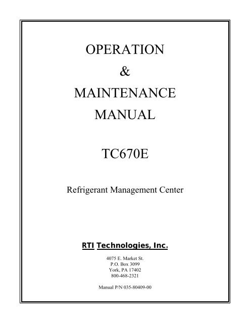
<strong>OPERATION</strong>&<strong>MAINTENANCE</strong><strong>MANUAL</strong><strong>TC670E</strong>Refrigerant Management Center<strong>RTI</strong> <strong>Technologies</strong>, Inc.4075 E. Market St.P.O. Box 3099York, PA 17402800-468-2321Manual P/N 035-80409-00
<strong>TC670E</strong>CONVE<strong>RTI</strong>BLERECYCLING MACHINEThis Recycling Machine wasmanufactured by <strong>RTI</strong> in compliancewith all applicable UnderwritersLaboratories (UL) and Society ofAutomotive Engineers (SAE)Standards and Specifications forRefrigerant Recycling Equipment.Your machine is initially configuredto recycle R12 or R134a.An <strong>RTI</strong> Retrofit Kit is available forfield conversion of this machine torecycle the alternate refrigerant forwhich it is now configured. This kitincludes complete instructions, labels,filters, hoses with service couplers,and special tools required to make theconversion.Once converted by an <strong>RTI</strong>Authorized Representative, a newSerial Label (included in the kit) willbe affixed to the machine. This SerialLabel will certify that the machine isthen in compliance with all SAE andUL Standards and Specifications forEquipment to recycle the alternaterefrigerant.
TABLE OF CONTENTS<strong>TC670E</strong>Start-Up Instructions ............................. 3Safety Precautions ............................... 4Filling the Charging Cylinder ....................... 6Recover/Recycle................................. 7Oil Drain & Air Purge ............................ 9Deep Vacuum................................... 10Hose Evacuation................................. 11Charge/High Side ................................ 12Scheduled Maintenance & Filter Maintenance ......... 14Problems & Solutions ............................ 15Flow Diagram................................... 17Schematic Diagram .............................. 18FSC to ACME Adapter ........................... 19CONGRATULATIONS:You have purchased one of the finest Recovery, Recycling, andCharging Machines available at any price.Fill out and return the Warranty Card within 90 days to activatewarranty and free lifetime technical support.
<strong>RTI</strong> <strong>Technologies</strong>, Inc.START-UP INSTRUCTIONS1) Check for any shipping damage. Place a claim with carrier if damage is discovered.2) Complete and return the Warranty Card to activate Technical Support and Warranty Coverage.Warranty claims can not be honored without this warranty card on file.BEFORE USING THE <strong>TC670E</strong>Check for any shipping damage. Place a claim with carrier if damage is discovered.DO NOT USE A DAMAGED UNIT.Complete and return the Warranty Card to activate technical support service and warranty coverage.Warranty claims can not be honored without this warranty card on file.The <strong>TC670E</strong> should not be operated or serviced by any person who has not read all the contents ofthis manual. Failure to read and comply with these instructions or any one of the limitations notedherein can result in serious injury and/or property damage.These general instructions describe normal operation and maintenance situations encountered withthe <strong>TC670E</strong>. The instructions should not be interpreted to anticipate every possible contingency.It is the responsibility of the owner/user to operate the <strong>TC670E</strong> in accordance with all specificationsand laws which may apply.The following pages contain rules for safe operation of the <strong>TC670E</strong>. Taking precedence over anyspecified rule listed herein, however, is the most important rule of all:"USE COMMON SENSE"A few minutes spent reading these instructions can make an operator aware of dangerous practicesto avoid and precautions to take for his own safety and the safety of others.A regular schedule of inspection of the <strong>TC670E</strong> should be established and records maintained withspecial attention given to Hoses, Compressor Oil Level, Moisture Indicator, and Filters.September 19, 1997 Page 3
<strong>RTI</strong> <strong>Technologies</strong>, Inc.SAFETY PRECAUTIONS! Recover, Recycle, and Charge only the refrigerant for which the machine is configured.! Wear safety glasses and protective gloves. Refrigerant has a very low boiling point and cancause frostbite.! Follow the <strong>TC670E</strong> operating procedures sequentially to avoid prematurely disconnecting hosesor opening valves which may release refrigerant to the atmosphere.! Do not expose the <strong>TC670E</strong> to moisture or operate in wet areas.! Use the <strong>TC670E</strong> in locations with mechanical ventilation that provides at least four air changesper hour.! Hoses used with the <strong>TC670E</strong> must have shutoff devices within 12 inches of the connectionpoint to the system being serviced to minimize the introduction of Non-condensable Gas (Air)into the <strong>TC670E</strong> and the release of refrigerant when being disconnected.! Disconnect power before performing any maintenance or service on the <strong>TC670E</strong>.! Avoid using an extension cord with the <strong>TC670E</strong>. If necessary, use a good condition, UL listed,3-wire grounded, #14 AWG extension cord of the shortest possible length.! Connect the <strong>TC670E</strong> to a properly protected, grounded receptacle. Do not over load the circuit.! Do not allow the <strong>TC670E</strong> to remain unattended in the Charge Mode with power On. TheCharge Cylinder Heater will be energized creating a high pressure condition.NEVER TURN THE CYLINDER UP-SIDE-DOWN.DO NOT CONNECT THE <strong>TC670E</strong> TO THE LIQUID SIDE OF ANYA/C SYSTEM WITH A CAPACITY GREATER THAN 4 LBS.REFRIGERANT IN A/C SYSTEMS HAVING LARGER CAPACITIESMUST BE RECOVERED FROM THE VAPOR SIDE ONLY.NEVER CONNECT THE <strong>TC670E</strong> TO THE LIQUID PORT OF ACYLINDER OF REFRIGERANT TO FILL THE <strong>TC670E</strong> CHARGE CYLINDER.FAILURE TO FOLLOW THE ABOVE MAY CAUSE THE <strong>TC670E</strong> COMPRESSOR TOFAIL AND VOID THE WARRANTY.September 19, 1997 Page 4
<strong>RTI</strong> <strong>Technologies</strong>, Inc.i CAUTION TAvoid breathing refrigerant or lubricant vapor or mist.Exposure may irritate eyes, nose and throat.If accidental system discharge occurs, ventilate work area before resumingservice.Additional health and safety information may be obtained from refrigerant andlubricant manufacturers.Special Considerations with R134aR134a has been shown to be nonflammable at ambient temperature andatmospheric pressure. However, tests under controlled conditions have indicatedthat, at pressures above atmospheric and with air concentrations greater than 60%by volume, R134a can form combustible mixtures.While it is recognized that an ignition source is also required for combustion tooccur, the presence of combustible mixtures is a potentially dangerous situationand should be avoided.Under no circumstances should any equipment be pressure tested or leak testedwith Air/R134a mixtures. Do not use compressed air (shop air) for leak detectionin R134a systems.September 19, 1997 Page 5
<strong>RTI</strong> <strong>Technologies</strong>, Inc.FILLING THE CHARGING CYLINDERA/C Systems requiring service often do not have a full charge of refrigerant. To avoid unnecessaryrepositioning of hoses it is recommended that the <strong>TC670E</strong> be filled until about 3 pounds of liquidrefrigerant can be seen in the Charging Cylinder Sight Glass. The Sight Glass is visible through aslotted opening on the front of the <strong>TC670E</strong>.Figure 1 Filling the CylinderTo fill the <strong>TC670E</strong> Charge Cylinder, refer to Figure 1 and follow these steps:1. Connect the Low Side Blue Hose to the VAPOR port of a cylinder of new or recycledrefrigerant. An adapter is provided with the <strong>TC670E</strong> (R134a) which permits the Field ServiceCoupler to be attached to the .500 ACME fitting on the cylinder of refrigerant.If the cylinder has two ports, observe that the embossed marking on the cylinder knob saysVAPOR or GAS. Do not rely on color coding of the knobs on the valves.DO NOT CONNECT TO THE LIQUID VALVE.DO NOT TURN THE CYLINDER UP-SIDE DOWN.INTRODUCTION OF LIQUID INTO THE <strong>TC670E</strong> MAY DAMAGE THECOMPRESSOR AND VOID THE WARRANTY.2. Press top (ON) of rocker switch marked RECOVER/RECYCLE.The <strong>TC670E</strong> will recover and recycle refrigerant into the Charging Cylinder. Observe the liquidrefrigerant level rise in the Charging Cylinder Sight Glass and when at approximately 3 lbs.close the valve on the refrigerant cylinder. Allow the <strong>TC670E</strong> to continue running until theLow Side Gauge shows a vacuum. This will evacuate the Blue Hose.3. Press bottom (OFF) of rocker switch marked RECOVER/RECYCLE.September 19, 1997 Page 6
<strong>RTI</strong> <strong>Technologies</strong>, Inc.RECOVER/RECYCLEFigure 2 Recover/RecycleTo Recover/Recycle, refer to Figure 2 and follow these steps:1. Attach Red and Blue Hoses to the A/C system per the vehicle manufacturer's instructions.Note For R134a MachinesField Service Couplings on the ends of Service Hoses are of a special design.The valves have LEFT HAND threads which makes operation opposite to that of others.To Close...To Open...Turn Counter-clockwiseTurn ClockwiseThe valves MUST BE CLOSED before connecting or disconnecting Field Service Couplings.2. Open High and Low Gauge Valves.3. Open Red and Blue Hose Valves.4. Press top (ON) of rocker switch marked RECOVER/RECYCLE.The <strong>TC670E</strong> will automatically recover and recycle refrigerant from the A/C System until avacuum is sensed. This vacuum level can be seen on the Low Side Gauge.September 19, 1997 Page 7
... NOTE ...<strong>RTI</strong> <strong>Technologies</strong>, Inc.! DO NOT TURN THE <strong>TC670E</strong> OFF OR DISCONNECT HOSES !A small quantity of Liquid refrigerant will probably still remain in the A/C System. This canbe detected by observing an increasing pressure reading on the Low Side Gauge.As pressure increases to a preset level, the <strong>TC670E</strong> will automatically cycle on and off tocontinue recovering refrigerant.Allow this automatic sequence to repeat until the vacuum level remains constant for at least 2minutes.As refrigerant is processed by the <strong>TC670E</strong>, temperature variations can cause vapor tochange to liquid which may temporarily settle in various internal components.If a known amount of refrigerant has been introduced into the <strong>TC670E</strong> it may not all beseen in the Charging Cylinder Sight Glass.This is normal and nothing to be concerned about. Refrigerant has not been lost.The sight glass does not indicate the amount of refrigerant recovered. It is onlyaccurate for determining the amount of refrigerant charged out to the vehicle A/C Systemwhile in the Charge Mode of operation.5. Close Red and Blue Hose Valves.6. Close High and Low Gauge Valves.7. Press bottom (OFF) of rocker switch marked RECOVER/RECYCLE.PURGE REQUIRED OR CYLINDER FULL LIGHT:This Light will illuminate if either...1) The Charging Cylinder has filled to capacity: Go to Page 12.OR2) Pressure on the Purge Gauge approaches 17 bar: Go to Page 9.September 19, 1997 Page 8
<strong>RTI</strong> <strong>Technologies</strong>, Inc.OIL DRAIN & AIR PURGEOil and Non-condensable Gas (Air) are separated fromthe recovered refrigerant and MUST be removedfollowing EACH recycling procedure as follows:1. MOMENTARILY press the Purge Button (To theright of the Purge Chart) and hold until the pressurereading on the Pressure Gauge above this buttondrops one small graduation mark (approximately 10PSIG).2. SLOWLY open the Oil Drain Valve (Lower leftside on back of <strong>TC670E</strong>) to vent Non-condensableGas and drain any oil which may have beenremoved from the A/C System. A plastic cup isprovided to collect the oil.Unless the A/C System had previously beenoverfilled, the <strong>TC670E</strong> will typically not removemore than a tablespoon of oil, making replenishmentunnecessary.Leave the Oil Drain Valve open.3. Determine the room temperature.4. Locate the pressure (PSIG) corresponding to thisroom temperature ( 0 F) in the chart on the top of the<strong>TC670E</strong>. This chart is reproduced at the right.If the pressure indicated on the gauge is greater thanthat determined from the chart...SLOWLY press and hold the Purge Button untilthe gauge pressure equals that shown in the chart.Any Non-condensable Gas will be ventedthrough the Oil Drain Valve.5. Close the Oil Drain Valve.6. Press the Purge Button and hold for approximately5 seconds. This permits any residual NoncondensableGas to be recirculated for reprocessingduring the next recycle procedure.0 F R12 R134a30 42 4032 44 4234 46 4436 48 4638 50 4940 52 5142 54 5444 57 5646 59 5948 61 6150 64 6452 66 6754 69 7056 72 7258 74 7660 77 7862 80 8264 83 8566 85 8868 88 9270 92 9572 95 9774 98 10476 102 10778 105 11080 108 11482 112 11884 115 12386 118 12788 123 13090 127 13592 130 14094 135 14596 138 14898 143 153100 147 157102 150 163104 155 167106 160 173108 165 180110 168 185112 173 190114 178 195116 183 200118 188 207Purge ChartSeptember 19, 1997 Page 9
<strong>RTI</strong> <strong>Technologies</strong>, Inc.VACUUMIf the A/C System is "opened" for replacing components, it is important to draw a vacuum on thesystem before recharging with refrigerant. The following steps should be followed:Figure 3 VacuumTo Vacuum the A/C System, refer to Figure 3 and follow these steps:1. Connect Red and Blue Hoses to the high and low sides of the A/C System.2. Open Low and High Gauge Valves.3. Open Red and Blue Hose Valves.4. Press top (ON) of rocker switch marked DEEP VACUUM.5. The Pump will start and the <strong>TC670E</strong> will start drawing a vacuum which will be indicated bya dropping pressure on the Low Gauge.NOTE:ALSO:If pressure is sensed at the Red and Blue Hoses on the <strong>TC670E</strong>, the Vacuum Pump willnot start, as this would result in venting of refrigerant. If this occurs, perform therecover/recycle operation described earlier.It is normal for the <strong>TC670E</strong> to have a 20 to 30 second discharge when the pump isstarted.September 19, 1997 Page 10
<strong>RTI</strong> <strong>Technologies</strong>, Inc.HOSE EVACUATIONIt's important that Air not be introduced into the A/C System during a Charging procedure. If a DeepVacuum procedure was performed previously, the following Hose Evacuation Procedure is notrequired. If the service valves on the hoses have been open, the following procedure must beperformed:Figure 4 Hose EvacuationTo Evacuate Hoses, refer to Figure 4 and follow these steps:1. Close Red and Blue Hose Valves.2. Open High and Low Gauge Valves.3. Press top (ON) of rocker switch marked RECOVER/RECYCLE.4. Let the <strong>TC670E</strong> run until a vacuum is seen on the Low Side Gauge.5. Turn High and Low Gauge Valves to OFF.6. Press bottom (OFF) of rocker switch marked RECOVER/RECYCLE. All Air has now beenremoved from the Hoses.7. Vent any Non-condensable Gas as described in the previous section.September 19, 1997 Page 11
<strong>RTI</strong> <strong>Technologies</strong>, Inc.CHARGE - HIGH SIDEFigure 5 Charge - High SideTo Charge Refrigerant, refer to Figure 5 and follow these steps:1. Perform Hose Evacuation described previously.2. Connect Red Hose to the A/C System high side per the vehicle manufacturer's instructions. Donot open the hose valve.3. Press top (ON) of rocker switch marked CHARGE/HIGH SIDE. The Charge Cylinder will nowbe heating to develop pressure for charging.4. Open High Gauge Valve. The Low Gauge Valve and both Hose Valves should be closed.5. Determine the refrigerant capacity of the A/C system to be charged. This data is usually printedon a tag located on the accumulator or under the hood of the vehicle. Convert this quantity totenths of a pound for setting the <strong>TC670E</strong> charge indicator.The following will determine where to set the indicator prior to starting the charge mode:(<strong>TC670E</strong> Liquid Level) - (A/C System Capacity) = Indicator SettingSeptember 19, 1997 Page 12
<strong>RTI</strong> <strong>Technologies</strong>, Inc.EXAMPLE:The level of liquid visible in the <strong>TC670E</strong> Charging Cylinder Sight Glass is 7.4 lbs.and the A/C system capacity is 3.2 lbs. The following calculation results...(7.4) - (3.2) = 4.2Therefore, the sliding indicator should be set at 4.2 lbs. in this example. When theliquid level lowers to the 4.2 lb. mark, a charge of 3.2 lbs. will have been deliveredNOTE...The Sight Glass on the Charging Cylinder has markings for both R12 andR134a. Always use the correct scale for accurate charging.6. Open Red Hose Valve. Do not start the Vehicle's Engine. Refrigerant will flow into the highside of the A/C System. Closely monitor the liquid level as it lowers in the Charging CylinderSight Glass.7. Close High Gauge Valve as soon as the refrigerant level drops to the sliding indicator.9. Press bottom (OFF) of rocker switch marked CHARGE/HIGH SIDE.The vehicle can now be started and the A/C system checked by monitoring Gauge pressures.Evacuate the hoses per the preceding section "Hose Evacuation"Always close all valves before disconnecting hoses.NOTE:The preceding is the recommended method of charging with the <strong>TC670E</strong>.Some vehicle manufacturers may specify connecting only to the Low Side of theA/C System. Always follow the manufacturer’s recommended procedures. Theabove instructions would have to be modified accordingly.September 19, 1997 Page 13
<strong>RTI</strong> <strong>Technologies</strong>, Inc.SCHEDULED <strong>MAINTENANCE</strong>BEFORE EACH USE...Check the oil level in the Compressor DAILY before using.The Oil Level Sight Tube is visible through a cut-out in the left side of the black Compressor Coverat the bottom of the <strong>TC670E</strong>.The oil level should be visible in the small nylon tube.If oil is not visible or is above the middle of the cut-out call Technical Support at 800-468-2321.MONTHLY...Clean the Condenser to maintain high efficiency performance of the <strong>TC670E</strong>. Disconnect powerand remove the Compressor Compartment Cover and blow compressed air through the cooling finsof the Condenser to remove any debris.Do not bend the fins on the Condenser coil. Air flow will be restricted and cause damage to the<strong>TC670E</strong>. Replace the Compressor Compartment Cover before applying power to the <strong>TC670E</strong>.FILTER <strong>MAINTENANCE</strong>Monitor the Moisture Indicator for a color change from BLUE to PINK. When the <strong>TC670E</strong> is newand immediately after changing Combo Filters, the Moisture Indicator may show PINK. This is dueto the exposure to air and does not indicate inadequate filter performance.Two Combo Filters are installed on the rear of the <strong>TC670E</strong>.Both Filters must be changed every year OR when the Moisture Indicator shows "Wet".September 19, 1997 Page 14
<strong>RTI</strong> <strong>Technologies</strong>, Inc.PROBLEMS & SOLUTIONSOn rare occasion the <strong>TC670E</strong> may seem to be performing differently or not at all. Experience hasshown that varying operating conditions can affect the performance characteristics of the <strong>TC670E</strong>.The temperature of the vehicle A/C System will affect how the <strong>TC670E</strong> performs.Following are typical problems with explanations of the possible cause and solution.PROBLEM:SOLUTION:My <strong>TC670E</strong> worked fine all last Summer. I got it out today for the first service jobthis Spring and it is very slow in evacuating the system.Today's Spring temperature may be much lower than the average temperaturesduring the summer months. Maybe the vehicle was brought in from outside wherethe temperature is very low.The refrigerant in the vehicle will not be under as high a pressure at lowertemperatures and the <strong>TC670E</strong> will take longer to draw a vacuum. More cycles maybe required to completely recover the refrigerant.PROBLEM:SOLUTION:PROBLEM:SOLUTION:PROBLEM:SOLUTION:I put 5 lbs. of refrigerant into the <strong>TC670E</strong> using the Recycle Mode. When Ichecked the sight glass on the Charging Cylinder, there was less than 5 lbs. I lostRefrigerant. The unit must leak.Due to temperature changes, some refrigerant may condense into liquid form andstay in tubes and other components in the circuit preceding the Charging Cylinder.This is normal and will explain why all refrigerant is not visible in the sight glass.I can not get the <strong>TC670E</strong> to draw a vacuum as indicated on the Low Side Gauge.Check Hoses for restrictions.When I try to fill the Charging Cylinder from an auxiliary cylinder of cleanrefrigerant, the <strong>TC670E</strong> is really slow or shuts down.The auxiliary cylinder will cool due to the vaporization of refrigerant. This causesthe pressure to decrease.Use a heat belt to increase the speed of recycling by the <strong>TC670E</strong>.September 19, 1997 Page 15
<strong>RTI</strong> <strong>Technologies</strong>, Inc.PROBLEM:SOLUTION:I turned a 30 lb. cylinder of new refrigerant up-side-down to pre-charge theCharging Cylinder with liquid. The Charging Cylinder didn't fill and now the<strong>TC670E</strong> won't recover from an A/C system.The <strong>TC670E</strong> has been overloaded with liquid refrigerant (See Safety PrecautionSection at the beginning of this manual).... WARNING ...IF A CYLINDER IS TURNED UP-SIDE-DOWN, THE<strong>TC670E</strong> WILL OVERFILL WITH LIQUIDREFRIGERANT. THIS OVER FILLS THE SUCTIONACCUMULATOR WITH LIQUID.FROST ON THE OIL DRAIN ON THE REAR OF THE<strong>TC670E</strong> IS A GOOD INDICATION OF THISOCCURRENCE.THIS SYMPTOM IS CAUSE FOR CONCERN AS LIQUIDREFRIGERANT WILL BE FORCED INTO THECOMPRESSOR.THIS CAN DESTROY THE COMPRESSOR AND WILLVOID THE WARRANTY.The safest method to remove the excess liquid which has collected in the SuctionAccumulator is to drain it from the Oil Drain on the back of the <strong>TC670E</strong> as follows:Draw a deep vacuum (25 to 29 In. Hg.) on an empty cylinder and connect it to theOil Drain Valve. Open the cylinder valve and the Oil Drain valve.Close the valves and disconnect the cylinder after the liquid has been drawn into thecylinder. This refrigerant can now be recycled by the <strong>TC670E</strong> following normalrecycling procedures.If the above suggested solutions do not solve the problem, call the phone number shown on theSerial Label on the rear of the machine and one of our technicians will help diagnose the cause.Please have the Serial Number available for reference.September 19, 1997 Page 16
<strong>RTI</strong> <strong>Technologies</strong>, Inc.September 19, 1997 Page 17
<strong>RTI</strong> <strong>Technologies</strong>, Inc.September 19, 1997 Page 18
<strong>RTI</strong> <strong>Technologies</strong>, Inc.September 19, 1997 Page 19