Series 9820Q ASTRA Installation/Operation Manual - Gasboy
Series 9820Q ASTRA Installation/Operation Manual - Gasboy
Series 9820Q ASTRA Installation/Operation Manual - Gasboy

You also want an ePaper? Increase the reach of your titles
YUMPU automatically turns print PDFs into web optimized ePapers that Google loves.
<strong>Series</strong> <strong>9820Q</strong> <strong>ASTRA</strong><strong>Installation</strong>/<strong>Operation</strong> <strong>Manual</strong>MDE-4339(formerly 035090)
Computer Programs and DocumentationAll <strong>Gasboy</strong> International Inc. computer programs (including software on diskettes and within memory chips) and documentation are copyrighted by, and shall remain the property of, <strong>Gasboy</strong>International Inc. Such computer programs and documents may also contain trade secret information. The duplication, disclosure, modification, or unauthorized use of computer programs ordocumentation is strictly prohibited, unless otherwise licensed by <strong>Gasboy</strong> International Inc.FCC WarningThis equipment has been tested and found to comply with the limits for a Class A digital device pursuant to Part 15 of the FCC Rules. These limits are designed to provide reasonable protectionagainst harmful interference when the equipment is operated in a commercial environment. This equipment generates, uses, and can radiate radio frequency energy, and if not installed and usedin accordance with the instruction manual, may cause harmful interference to radio communications. <strong>Operation</strong> of this equipment in a residential area is likely to cause harmful interference inwhich case the user will be required to correct the interference at his own expense. Changes or modifications not expressly approved by the manufacturer could void the user’s authority to operatethis equipment.ApprovalsGilbarco is an ISO 9001:2000 registered company.Underwriters Laboratories: New York City: California Air Resources Board (CARB):U.L. File# Products listed with U.L. NYFD of A # Product Executive Order # ProductMH4314All dispensers and self-contained pumping 4823 9100A, 9140A, 9152A, 9153A,9800A, 9840A, 9850A, 9852A,9853A, 9140Power operated Transfer Pump Models 25,MH6418 26, 27, 28, 72, 72S, 72SP, 72X, 73 and 182 4997 9822A, 9823AMH7404 Hand operated Transfer Pump Models 123 5046 pending 9100Q, 9140Q, 9152Q, 9153Q<strong>Series</strong>, 1243 <strong>Series</strong>, 1520 and 1720 <strong>Series</strong>9800Q, 9840Q, 9852Q, 9853QMH10581 Key control unit, Model GKE-B <strong>Series</strong>Card reader terminals, Models 1000, 1000PSite controller, Model 2000S CFN <strong>Series</strong>Data entry terminals, Model TPK-900 SerieFuel Point Reader SystemG-70-52-AMG-70-150-AEBalance Vapor RecoveryVaporVacNCWM – Certificate of Compliance<strong>Gasboy</strong> pumps and dispensers are evaluated by the National Conference of Weights and Measures (NCWM) under the National Type Evaluation Program (NTEP).NCWM has issued the following Certificates of Compliance (COC):COC# Product Model # COC # Product Model # COC # Product Model #9100 Retail <strong>Series</strong>, 8700 91-019A295-179A2 Dispenser<strong>Series</strong>, 9700 <strong>Series</strong>91-0573A395-136A5 Dispenser 9800 <strong>Series</strong>DispenserDispenser9100 Commercial<strong>Series</strong>1000 <strong>Series</strong> FMS2000-CFN <strong>Series</strong>Patents<strong>Gasboy</strong> products are manufactured or sold under one or more of the following U.S. patents:Dispensers5,257,720Point of Sale/Back Office EquipmentD335,673TrademarksNon-registered trademarksRegistered trademarksConsola <strong>ASTRA</strong> ®Infinity Fuel Point ®<strong>Gasboy</strong> ®Keytrol ®Slimline ®Additional U.S. and foreign trademarks pending.Other brand or product names shown may be trademarksregistered trademarks of their respective holders.Additional U.S. and foreign patents pending.This document is subject to change without notice. • For information regarding <strong>Gasboy</strong> Literature, call (336) 547-5661E-mail: literature@gilbarco.com •· Internet: http://www.gasboy.com and http://www.gilbarco.com” 2004 <strong>Gasboy</strong> International Inc. and Gilbarco Inc. • All Rights Reserved
FCC InformationThe US Federal Communications Commission (FCC) requires specific information besupplied to the users of any equipment which may emit radio frequency energy. Pleaseread the following information.FCC Part 15This equipment has been tested and found to comply with the limits for a Class A digitaldevice, pursuant to Part 15 of the FCC rules. These limits are designed to providereasonable protection against harmful interference when the device is operated in acommercial environment. This equipment generates, uses, and can radiate radiofrequency energy and, if not installed in accordance with the instruction manual, maycause harmful interference to radio communications. <strong>Operation</strong> of this equipment in aresidential area is likely to cause harmful interference, in which case, the user will berequired to correct the interference at his own expense.
ContentsCONTENTSProduct....................................................................................................................................... 2Model # ...................................................................................................................................... 2Registered trademarks............................................................................................................... 2CONTENTSi1. Introduction 1Purpose...................................................................................................................................... 1General Description.................................................................................................................... 1Standard Features...............................................................................................................1Optional Features ................................................................................................................22. <strong>Installation</strong> 3<strong>Installation</strong> Precautions .............................................................................................................. 3Vent Line.................................................................................................................................... 4Vapor Recovery Option .............................................................................................................. 4Hose Length Estimator............................................................................................................... 4Typical <strong>Installation</strong>...................................................................................................................... 6011931 Base Layout, Models: 9822Q, 9823Q.....................................................................7011930 Base Layout, Models: 9822Q, 9823Q.....................................................................8011884 Base Layout, Models: 9822Q, 9823Q.....................................................................9011885 Base Layout, Models: 9822Q, 9823Q...................................................................10011885 Base Layout, Models 9822Q, 9823Q....................................................................113. Control Lines 13Purpose.................................................................................................................................... 13Ground..................................................................................................................................... 13Micro Feed ............................................................................................................................... 13Micro Neutral............................................................................................................................ 13Pump Motor Feed .................................................................................................................... 13Neutral Feed ............................................................................................................................ 14Slow Flow (Reset Complete/Switch Detect) ............................................................................. 14Fast Flow ................................................................................................................................. 14Phase 2 Feed........................................................................................................................... 14Pulser....................................................................................................................................... 14Pulse Output ............................................................................................................................ 14RS-485..................................................................................................................................... 154. Wiring 17Wiring Precautions................................................................................................................... 17Ground..................................................................................................................................... 18Circuit Breakers........................................................................................................................ 18Pump Motor.............................................................................................................................. 18Pulse Output ............................................................................................................................ 18RS-485..................................................................................................................................... 18Wire Size.................................................................................................................................. 19Conduit..................................................................................................................................... 20Terminal Block ID..................................................................................................................... 21023866 Wiring Diagram, Models: 9822Q, 9823Q .............................................................22MDE-4339 <strong>9820Q</strong> <strong>ASTRA</strong> <strong>Installation</strong>/<strong>Operation</strong> • Juy 2004Contents-i
GASBOY <strong>Series</strong> <strong>9820Q</strong>023866 Wiring Diagram, Models: 9822Q, 9823Q .............................................................23023867 Wiring Diagram, Models: 9822Q-2, 9823Q-2.......................................................24023867 Wiring Diagram, Models: 9822Q-2, 9823Q-2.......................................................255. Pump <strong>Operation</strong> 27Overview .................................................................................................................................. 27Electronic Component Access.................................................................................................. 28CPU Switch Settings ................................................................................................................ 29ATC Information Sheet............................................................................................................. 32Battery Back-Up Power Supply ................................................................................................ 33View/Reset Totalizer ................................................................................................................ 33Electronic Totalizer ............................................................................................................33Mechanical Totalizer..........................................................................................................34Operating Sequence ................................................................................................................ 34Nozzle Locking......................................................................................................................... 356. Start-Up and Test 36<strong>Installation</strong> Completion Checklist.............................................................................................. 36Start-Up.................................................................................................................................... 37Post Start-Up Tests.................................................................................................................. 37Voltage...............................................................................................................................37Tightness ...........................................................................................................................37Belts...................................................................................................................................37Calibration..........................................................................................................................377. Preventive Maintenance 39General .................................................................................................................................... 39Hints For Better Pump Performance ........................................................................................ 39Demand Competent Service .............................................................................................39Use Authorized Parts.........................................................................................................39Operate With Reasonable Care ........................................................................................39Preventive Maintenance Checklist............................................................................................ 39Keep Water Out.................................................................................................................39Clean the Dial Face ...........................................................................................................40Clean the Strainer..............................................................................................................40Change the Filter ...............................................................................................................40Adjust the Belts..................................................................................................................40Preserve the Finish of Your Pumps...................................................................................40WarrantyContents-ii MDE-4339 <strong>9820Q</strong> <strong>ASTRA</strong> <strong>Installation</strong>/<strong>Operation</strong> • July 2004
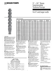
Introduction1. IntroductionPurposeThe GASBOY <strong>ASTRA</strong> <strong>Series</strong> <strong>9820Q</strong> Electronic Commercial Pumps <strong>Installation</strong>/<strong>Operation</strong><strong>Manual</strong> is provided to assist the installer in installing and operating the unit. This manual shouldbe supplied to the electrician prior to the installation of conduit and wiring to ensure the unit isinstalled properly. Faulty installations are the major cause of unit malfunctions. The unit must beinstalled and operated as described in this manual to ensure the reliability and proper operation ofthe <strong>Series</strong> <strong>9820Q</strong> unit. In addition to installation information, this manual contains warnings,safeguards and procedures on the use and care of the <strong>Series</strong> <strong>9820Q</strong> pumps. Be sure to leave thismanual with the pump owner after the installation is complete.General DescriptionThe GASBOY <strong>Series</strong> <strong>9820Q</strong> <strong>ASTRA</strong> (aboveground storage tank remote access) pump units areUL-listed and are available in two models. Model 9822Q is available in standard speed (up to 15GPM/56 LPM) with an intermittent-duty motor. Model 9823Q is available in high speed (up to 22GPM/83LPM) with a continuous-duty motor. The delivery rate varies depending upon installationconditions and added accessories. Both models of the <strong>9820Q</strong> offer electronic registration of thequantity dispensed.Standard FeaturesNOTE: NFPA regulations do not allow tank-mounted pumps to be used for the resale of fuel.The <strong>Series</strong> <strong>9820Q</strong> consists of two metal cabinet assemblies. One assembly is mounted on top ofthe tank and contains the pumping unit, meter, electronic pulser, and all hydraulics. The hose andnozzle are connected to this assembly. The second assembly is mounted at a height to permit easyaccess by a user. It contains the electronic register, controls, display and nozzle boot.The following lists detail the standard and optional features for the <strong>Series</strong> <strong>9820Q</strong>.• One-inch high, 6-digit, backlighted LCD display• 1000:1 dual-phase, error-checking pulser (gallons); 250:1 dual-phase, error-checking pulser(liters)• AC authorization line for control of the unit• Reset complete (switch detect) output which allows monitoring of the unit's operation when itis connected to an automated fueling system• Resettable electronic totalizer• Discharge elbow• Four piston, positive displacement meter.• Belt-driven, positive-displacement rotary vane pump with an 80 mesh (300 micron) strainerand integral air separation.• The standard pumping cabinet finish is white. The electronic register cabinet is black with ablue graphics panel.MDE-4339 <strong>9820Q</strong> <strong>ASTRA</strong> <strong>Installation</strong>/<strong>Operation</strong> • July 2004 1
GASBOY <strong>Series</strong> <strong>9820Q</strong>Optional Features• Pulser output drive line (open collector), capable of driving 1, 10, 100, 250, 500, or 1000pulses per unit (gallons) or 1, 10, 100, or 250 pulses per unit (liters)• RS-485 communication for direct connect to <strong>Gasboy</strong> CFN equipment• Battery backup for display of last transaction and capture of remnant pulse count in the eventof a power failure• Mechanical totalizer• Dual stage solenoid valve• A working voltage of 115 VAC (115/230 for motor) 60 HZ for domestic use, 230 VAC 50HZ/60 HZ for international use• Other options include Listed automatic nozzles, special lengths of Listed hose assembly,Listed dual swivels, UL-recognized filters, vapor recovery, and vapor recovery ready.2 MDE-4339 <strong>9820Q</strong> <strong>ASTRA</strong> <strong>Installation</strong>/<strong>Operation</strong> • July 2004
<strong>Installation</strong>2. <strong>Installation</strong><strong>Installation</strong> PrecautionsAll installations must conform with all building/fire codes, all Federal, State, and Local codes,National Electrical Code, (NFPA 70), NFPA 30, and Automotive and Marine Service Station Code(NFPA 30A) codes and regulations. Canadian users must also comply with the CanadianElectrical Code.Plan your installation carefully. A pump cannot be expected to work satisfactorily unless theinstallation is correct. Dispensing troubles, which seem to be pump-related, are frequently tracedto faulty installation. Review the following list of installation DO's and DON'T's to avoidpotential problems:1. DO read the WARNINGS page at the front of this manual, preceding the Table of Contents.It contains important information regarding the safe use of your dispensing equipment.2. DO install an emergency power cutoff. In addition to circuit breaker requirements of NFPA70 and NFPA 30A, a single control which simultaneously removes AC power from all sitedispensing equipment is recommended. This control must be readily accessible, clearlylabeled, and in accordance with all local codes.In a fuel management system application, the EMERGENCY STOP and STOP keys on theconsole and/or the optional EMERGENCY STOP button on the Island Card Reader do notremove AC power from equipment and under certain conditions, will not stop product flow.In order to provide the highest level of safety to you, your employees, and customers, werecommend that all employees be trained as to the location and procedure for turning offpower to the entire system.3. DO have the pump installed by a competent installer/electrician.4. DO install breakaway coupling on discharge hose. If using a high hose retriver, installbreakaway approximately 12" downstream of hose clamp on nozzle side of clamp.5. DO NOT experiment with a pump if you are not sure the installation is correct.6. DO NOT overload sub- or main breaker panels.7. DO NOT use power line wiring of inadequate capacity. (Use gauge specified by the wiringdiagram or wire chart provided in Section 4).8. DO NOT use a circuit breaker of improper size. (See Section 4).9. DO NOT use the GASBOY fuel dispensing equipment to remove water ballast from thestorage tank.10. DO NOT use gaskets on covers of explosion-proof type boxes. The sealing compound foundaround wires at various locations within conduit is a requirement of the National ElectricalCode and should not be disturbed. Ensure that the mating surfaces between the junction boxand cover are free of dirt, debris, nicks and scratches. Tighten junction box covers beforereplacing panels.11. DO NOT use knock-out boxes or flexible conduit for installing this unit. All power wiresshould be run in threaded, rigid, metal conduit. All threaded connections must be drawn uptight. All but one opening in the power junction box are provided with plugs at the factory.At completion of the installation, it is the installer's responsibility to ensure that any unusedopenings are plugged.MDE-4339 <strong>9820Q</strong> <strong>ASTRA</strong> <strong>Installation</strong>/<strong>Operation</strong> • July 2004 3
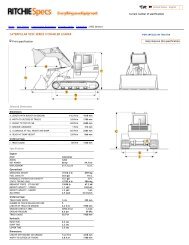
GASBOY <strong>Series</strong> <strong>9820Q</strong>Typical <strong>Installation</strong>See page 19 for cable requirements6 MDE-4339 <strong>9820Q</strong> <strong>ASTRA</strong> <strong>Installation</strong>/<strong>Operation</strong> • July 2004
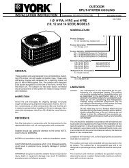
<strong>Installation</strong>011931 Base Layout, Models: 9822Q, 9823Q(View 1 - Pumping Unit Assembly)MDE-4339 <strong>9820Q</strong> <strong>ASTRA</strong> <strong>Installation</strong>/<strong>Operation</strong> • July 2004 7
GASBOY <strong>Series</strong> <strong>9820Q</strong>011930 Base Layout, Models: 9822Q, 9823Q(View 2 - Register Assembly)8 MDE-4339 <strong>9820Q</strong> <strong>ASTRA</strong> <strong>Installation</strong>/<strong>Operation</strong> • July 2004
<strong>Installation</strong>011884 Base Layout, Models: 9822Q, 9823Q(Optional Post)MDE-4339 <strong>9820Q</strong> <strong>ASTRA</strong> <strong>Installation</strong>/<strong>Operation</strong> • July 2004 9
GASBOY <strong>Series</strong> <strong>9820Q</strong>011885 Base Layout, Models: 9822Q, 9823Q(Side and Rear Brackets - View 1)10 MDE-4339 <strong>9820Q</strong> <strong>ASTRA</strong> <strong>Installation</strong>/<strong>Operation</strong> • July 2004
<strong>Installation</strong>011885 Base Layout, Models 9822Q, 9823Q(Side and Rear Brackets - View 2)MDE-4339 <strong>9820Q</strong> <strong>ASTRA</strong> <strong>Installation</strong>/<strong>Operation</strong> • July 2004 11
GASBOY <strong>Series</strong> <strong>9820Q</strong>12 MDE-4339 <strong>9820Q</strong> <strong>ASTRA</strong> <strong>Installation</strong>/<strong>Operation</strong> • July 2004
Control Lines3. Control LinesPurposeThis section is provided to familiarize the installer with the control inputs and outputs that areavailable for the <strong>Series</strong> <strong>9820Q</strong>. It is recommended the installer read these descriptions to obtain abetter working knowledge of the unit in order to guide him in planning the site wiring. ReferenceSection 4 for a specific wiring diagram and installation notes.The <strong>Series</strong> <strong>9820Q</strong> may be provided for use with 230 VAC power for international applications.The operating voltage for control lines to these units is shown in parentheses as (230 VAC Int'l).If connecting the <strong>9820Q</strong> to a GASBOY fuel management system, refer to the appropriate fuelmanagement system <strong>Installation</strong> <strong>Manual</strong> for detailed installation information.GroundTo ensure proper operation of the equipment and provide the necessary safety factors, a goodground line must be provided. A ground wire (preferably green) must be connected between theground screw of the register and the main electrical service panel. One (1) earth groundconnection is required per unit. The ground rod is to be a solid, corrosion-resistant conductor andmust be installed at the main electrical panel in accordance with the National Electrical Code. Itshould be properly tied into the ground bus strip of the panel. We recommend the neutral andground bus strips be bonded together (unless prohibited by local codes).Micro FeedThe Micro Feed is a 115 VAC (230 VAC Int'l) input required to power the microprocessor of theregister's electronics. This power must always remain on and must be on a separate breaker fromthe control lines (Pump Motor Feed). In a site configuration using multiple units, the power for themicroprocessors of up to 8 units can be supplied by one breaker.Micro NeutralThe Micro Neutral is a return line for AC current from the microprocessor of the dispensing unit tothe breaker panel.Pump Motor FeedThe Pump Motor Feed is a 115VAC (230 VAC Int'l) input which is required to power the pumpand authorize the control line. This line is used to provide authorization for the unit (when enabledthrough the DIP switches). If this line is controlled by a fuel management system using solid staterelays, a resistor assembly must be installed between the Pump Motor Feed line and Feed Neutralto prevent false triggering of the authorization input. The resistor assembly is 8.2K OHM, 10 Watt(P/N C05818) for 115/230 VAC domestic and 30K OHM, 10 Watt (P/N C06683) for 230 VACinternational wiring.The Pump Motor Feed line is used to power the slow flow and fast flow valves (when installed).The power used to control the pump is also provided by this line. The Reset Complete signal usedfor external monitoring of the pump originates from the Pump Motor Feed line.MDE-4339 <strong>9820Q</strong> <strong>ASTRA</strong> <strong>Installation</strong>/<strong>Operation</strong> • July 2004 13
GASBOY <strong>Series</strong> <strong>9820Q</strong>Neutral FeedThe Neutral Feed is the AC current return line back to the breaker panel for all attached devices(pump motor, solenoid valves).Slow Flow (Reset Complete/Switch Detect)The Slow Flow line is a 115VAC (230VAC Int'l) output which is used to control the slow flowvalve of the optional solenoid valve. This line also indicates when the reset process is completeand the unit is ready to dispense product. This line can be used in conjunction with a fuelmanagement system (for systems other than the <strong>Gasboy</strong> CFN <strong>Series</strong> systems).This line is capable of supplying 300 mA AC maximum (170 mA maximum if already connectedto the optional valve). This line must not be shorted to any conduit or chassis metal, mis-wired, orbe connected to any equipment requiring more than stated maximum allowable current. If theserestrictions are not followed, damage to the CPU PCB will occur.Fast FlowThe Fast Flow line is a 115VAC (230VAC Int'l) output which is used to control the fast flow valveof the optional solenoid valve.This line is capable of supplying 300 mA AC maximum (170 mA maximum if already connectedto the optional valve). This line must not be shorted to any conduit or chassis metal, mis-wired, orbe connected to any equipment requiring more than stated maximum allowable current. If theserestrictions are not followed, damage to the CPU PCB will occur.Phase 2 FeedThe Phase 2 Feed is a hot feed which is the opposite phase of the pump motor feed. This line andthe pump motor feed are used for 230VAC motor applications. If connected to equipmentrequiring control of the authorization input, the Phase 2 Feed should be switched through aseparate relay to prevent false triggering of the authorization signal.PulserThese lines are used to connect the pulser, mounted in the pumping unit, to the electronics in theregister assembly. These are DC voltage lines and provide the information necessary for theregister assembly to monitor the quantity of product dispensed. These lines are for internal useonly and must not be used for the pulse output (for external monitoring of the unit). Use theoptional Pulse Output interface if external pulses are required.Pulse OutputThis option provides a DC pulser output to indicate the quantity dispensed. This is an opencollector output. This output can sink up to 150 milliamps DC at voltages up to 24 VDC. Thepulse rate can be configured by a sealable DIP switch for rates of 1, 10, 100, 250, 500, or 1000pulses per gallon or 1, 10, 100 or 250 pulses per liter. This output should only be used whenmonitoring of the unit's operation is desired.14 MDE-4339 <strong>9820Q</strong> <strong>ASTRA</strong> <strong>Installation</strong>/<strong>Operation</strong> • July 2004
Control LinesRS-485When the dispensing unit includes the optional RS-485 interface, RS-485 lines are provided. Thisinterface allows the user to connect a GASBOY CFN <strong>Series</strong> System or TopKAT system directly tothe <strong>Series</strong> <strong>9820Q</strong> dispensing unit.MDE-4339 <strong>9820Q</strong> <strong>ASTRA</strong> <strong>Installation</strong>/<strong>Operation</strong> • July 2004 15
GASBOY <strong>Series</strong> <strong>9820Q</strong>16 MDE-4339 <strong>9820Q</strong> <strong>ASTRA</strong> <strong>Installation</strong>/<strong>Operation</strong> • July 2004
Wiring4. Wiring☎Customers and installers having any questions pertaining to the installation should contact theirGASBOY distributor.Wiring PrecautionsThe quality of the electrical installation is a major factor in maintaining proper safety levels andproviding trouble-free operation of your GASBOY pump. To assure a quality installation, followthese rules:1. All wiring must be installed to conform with all building/fire codes, all Federal, State, andLocal codes, National Electrical Code, (NFPA 70), NFPA 30, and Automotive and MarineService Station Code (NFPA 30A) codes and regulations. Canadian users must also complywith the Canadian Electrical Code.2. Use only threaded, rigid, metal conduit.3. Use only UL-Labeled insulated gasoline- and oil-resistant stranded copper wiring of theproper size.4. Wire connections should be tightly spliced and secured with a wire nut; close off the open endof the wire nut with electrical tape.5. The line to the motor should be on a separate circuit and installed on a 20 to 30 AMP breakerdepending on the motor size and/or the voltage setting.6. Install an emergency power cutoff. In addition to circuit breaker requirements of NFPA 70and NFPA 30A, a single control which simultaneously removes AC power from all sitedispensing equipment is recommended. This control must be readily accessible, clearlylabeled, and in accordance with all local codes.In a fuel management system application, the EMERGENCY STOP and STOP keys on theconsole and/or the optional EMERGENCY STOP button on the Island Card Reader do notremove AC power from equipment and under certain conditions, will not stop product flow.In order to provide the highest level of safety to you, your employees, and customers, werecommend that all employees be trained as to the location and procedure for turning offpower to the entire system.WARNING:To reduce the risk of electrical shock when servicing, turn off and lock out all power to the pump.AVERTISSEMENTPour réduire le risque de choc électrique lors de l'entretien/révision, coupez totalement le courant à lapompe/distributeur.Have the pump installed by a competent installer/electrician.MDE-4339 <strong>9820Q</strong> <strong>ASTRA</strong> <strong>Installation</strong>/<strong>Operation</strong> • July 2004 17
GASBOY <strong>Series</strong> <strong>9820Q</strong>GroundTo ensure proper operation of the equipment and provide the necessary safety factors, this unitmust be grounded. A ground wire (preferably green) must be connected between the ground screwof the register and the main electrical service panel. One (1) earth ground connection is requiredper unit. The ground rod is to be a solid, corrosion-resistant conductor and must be installed at themain electrical panel in accordance with the National Electrical Code. It should be properly tiedinto the ground bus strip of the panel. We recommend the neutral and ground bus strips be bondedtogether (unless prohibited by local codes).Circuit BreakersPower to the unit must be supplied from dedicated breakers. No other equipment should bepowered from these breakers. AC power for the micro power must come from a different breakerthan that of the pump. This not only provides electrical isolation for the micro power, but allowsthe unit to be disabled without shutting off power to the microprocessor PCB. The AC power forthe micro power may be grouped together for multiple units. It is recommended that no more than8 units be supplied from one breaker.Pump MotorPumps are shipped from the factory with motors wired according to the specifications given on theorder as to kind of current, frequency and voltage.Very often on installation, it becomes necessary to change the original setting to suit the AC powersource. To do this, locate the motor change-over plate and remove the screw which secures it inplace. Slide the plate so that the desired voltage, as marked on the plate, lines up with the screwhole. Reinsert the screw and secure the plate in place.Many motor failures result from improper setting of the motor change-over plate. If set for 115VAC and a 230 VAC feed is used, the motor will burn out after running only a short time. If setfor 230 VAC and a 115 VAC feed is used, the motor will run very slowly and the starting field willsoon burn out.Pulse OutputThe Pulse Output option provides the means for an external system to monitor the quantity that isdispensed by the <strong>9820Q</strong> dispensing unit. A description of the interface is provided in ControlLines, Pulse Output, in Section 3. Consult the wiring diagrams provided in Wiring in Section 4,along with the installation manual of the system that will be connected to the <strong>9820Q</strong> dispensingunit.RS-485The RS-485 option provides the means for direct connection to a GASBOY CFN <strong>Series</strong> System orTopKAT System. Consult the wiring diagrams provided in Wiring in Section 4, along with theinstallation manual of the CFN <strong>Series</strong> System or TopKAT System for proper wiring.18 MDE-4339 <strong>9820Q</strong> <strong>ASTRA</strong> <strong>Installation</strong>/<strong>Operation</strong> • July 2004
WiringWire SizeThe AC wire size for the Micro Feed and Neutral should be 14 AWG. This gauge of wire will besufficient for runs up to 300 feet from the breaker panel to the dispensing unit. Sites with distancesover 300 feet should use 12 AWG wire. In cases where multiple units are powered from the samebreaker through the same wires, the gauge of the wires should be increased to handle the addedload according to the distance from the breaker panel.The AC wire size of the Pump Motor Feed, Pump Motor, Feed Neutral, and Neutral isdependent upon the HP rating of the pump motor, the voltage at which the pump will be operated(115/230 VAC), and the distance from the circuit breaker panel to the pump. The chart belowshould be used as a guide in selecting the proper wire size according to the specific installationrequirements.The AC wire size for the Slow Flow, Fast Flow lines should be 14 AWG (when they are used).The DC wire size for the Pulser lines connecting the pumping unit to the register assembly mustuse four conductor, 18 AWG shielded cable (Belden 89418, <strong>Gasboy</strong> P/N C08864). This cableallows the pulser wires to run in the same conduit as the AC wiring for the short distance betweenthe pumping unit and the register assembly. Belden 89418 is rated as follows:Gas and Oil resistant insulation & jacket18 AWG tinned, stranded, copperFour conductors300 volt maximum operating voltageAluminum/Mylar shielded with drain wireTwisted-pair shielded cable is highly recommended for the Pulse Output or RS-485 field wiring(when they are used). This type of cable provides superior noise immunity and must be used fordistances over 100 feet or any time pulse output or RS-485 wiring is included in the same conduitas the AC wires. This cable must meet the following specifications:Conductor: 18 AWG stranded wire. 2 twisted-pairs.Shield: Foil-wrapped 100% coverage and/or tinned copper braid 90% coverageDrain Wire: Stranded, tinned copper, 20 AWG or larger/or braided shieldVoltage Rating: Maximum operating voltage of 600VEnvironmental: Gas- and oil-resistant; suitable for wet or dry locations.GASBOY can supply Belden 1063A (P/N C09655) which is a UL-Listed, 4-conductor cable thatmeets the requirements listed above. NOTE: Belden 1063A is UL-Listed but not CSA listed.Cable with a voltage rating of less than 600V must be installed in a conduit separate from all ACwires.See the GASBOY Fuel Management System <strong>Installation</strong> <strong>Manual</strong> for specific requirements.MDE-4339 <strong>9820Q</strong> <strong>ASTRA</strong> <strong>Installation</strong>/<strong>Operation</strong> • July 2004 19
GASBOY <strong>Series</strong> <strong>9820Q</strong>ConduitAll wiring to the GASBOY <strong>Series</strong> <strong>9820Q</strong> dispensing unit must be installed in threaded, rigid,metal conduit. PVC IS NOT ACCEPTABLE. Wiring between the <strong>9820Q</strong> register and pumpingunit is installed in a single conduit. This includes the wiring for the AC control of the pumpingunit and the internal pulser. A special cable, as described in Section 4, Wire Size, must be used forthe connection between the pulser inside the pumping unit to the register assembly.It is recommended that high voltage AC power wires to the register assembly (not between theregister and pumping unit), be installed in separate conduit from the low voltage pulser outputwires (when used). However, if AC and DC power wires share conduit, DC wiring must consist ofUL-Listed cable with the specifications described in Section 4, Wire Size. Only AC wires for thesystem and dispensers can be installed in this conduit for this application. Wiring between a FuelPoint Reader (FPR) and its pre-amp junction box is intrinsically safe and must be run in a conduitwith only other intrinsically safe wiring. It cannot be run in conduit with AC, DC, RS-485, orpulser wiring, regardless of the cable type used. See the Fuel Point Reader <strong>Installation</strong> andRetrofit <strong>Manual</strong>, C35628 for details.The GASBOY Warranty will not apply to any dispenser in which the AC and DC wires are run inthe same conduit, J-Box or wireway except as noted. The GASBOY Warranty will not apply toany dispenser using PVC as conduit.When the GASBOY <strong>Series</strong> <strong>9820Q</strong> dispensing unit is being installed with a fuel managementsystem other than a GASBOY system, see the manufacturer's installation manual for their specificconduit requirements.All wiring and conduit runs must conform with all building/fire codes, all Federal, State, and Localcodes, National Electrical Code, (NFPA 70), NFPA 30, and Automotive and Marine ServiceStation Code (NFPA 30A) codes and regulations. Canadian users must also comply with theCanadian Electrical Code.Use the following charts as a guideline for determining the necessary conduit sizes for wiring ofthe GASBOY <strong>Series</strong> <strong>9820Q</strong> dispensing unit. When actually determining the size of conduit, itmay be necessary to increase the size of conduit because of a long run or large amount of bends.The installer should determine the orientation of the wire runs according to the layout of thecomponents at the site and the applicable GASBOY wiring diagrams.To determine conduit size needed, use the THHN/THWN Wire Areas table (left) to find the areafor each wire gauge. Add up all wire areas. Use the Areas of Trade Size Conduit Table (right) toselect the smallest number in the 25% fill area (based on NEC 501-1) that comes closest withoutexceeding the total wire area.20 MDE-4339 <strong>9820Q</strong> <strong>ASTRA</strong> <strong>Installation</strong>/<strong>Operation</strong> • July 2004
WiringTerminal Block IDThe terminal blocks shown below are located in the register assembly.MDE-4339 <strong>9820Q</strong> <strong>ASTRA</strong> <strong>Installation</strong>/<strong>Operation</strong> • July 2004 21
GASBOY <strong>Series</strong> <strong>9820Q</strong>023866 Wiring Diagram, Models: 9822Q, 9823QDomestic 115/230 VACNOTES:1. All wiring and conduit runs must conform with all building/fire codes, all Federal, State, andLocal codes, National Electrical Code, (NFPA 70), NFPA 30, and Automotive and MarineService Station Code (NFPA 30A) codes and regulations. Canadian users must also complywith the Canadian Electrical Code.2. Pump motor can be wired as 230 VAC to reduce current draw. See breakaway view of 230VAC PUMP MOTOR. All other wiring should remain the same except for the addition ofthe L2 (requires 230 VAC breaker for control). If connected to equipment requiring controlof the authorization input, the Phase 2 Feed should be switched through a separate relay toprevent false triggering of the authorization signal.3. If the PUMP MOTOR line is controlled by a fuel management system using solid staterelays, a resistor assembly must be installed between the Pump Motor Feed line and Neutral toprevent false triggering of the authorization input. The resistor assembly is 8.2K OHM, 10Watt (P/N C05818) for 115/230 VAC domestic and 30K OHM, 10 Watt (P/N C06683) for230 VAC international wiring.4. SLOW FLOW and FAST FLOW lines are typically used when connecting to an optionalvalve. Each of these lines is capable of supplying 300 mA AC maximum (170 mA ACmaximum if already connected to the optional valve). These lines must not be shorted toany conduit or chassis metal, mis-wired, or connected to any equipment requiring morethan stated maximum allowable current. If these restrictions are not followed, damageto the CPU PCB will occur.5. Use the wire size chart listed when determining the wire size for the control wiring.22 MDE-4339 <strong>9820Q</strong> <strong>ASTRA</strong> <strong>Installation</strong>/<strong>Operation</strong> • July 2004
Wiring023866 Wiring Diagram, Models: 9822Q, 9823QDomestic 115/230 VACWARNING:Failure to follow the correct wiring diagram and all the listed notes and precautions may result indamage to the CPU PCB.MDE-4339 <strong>9820Q</strong> <strong>ASTRA</strong> <strong>Installation</strong>/<strong>Operation</strong> • July 2004 23
GASBOY <strong>Series</strong> <strong>9820Q</strong>023867 Wiring Diagram, Models: 9822Q-2, 9823Q-2International 230VACNOTES:1. All wiring and conduit runs must conform with all building/fire codes, all Federal, State, andLocal codes, National Electrical Code, (NFPA 70), NFPA 30, and Automotive and MarineService Station Code (NFPA 30A) codes and regulations. Canadian users must also complywith the Canadian Electrical Code.2. If the PUMP MOTOR line is controlled by a fuel management system using solid staterelays, a resistor assembly must be installed between the Pump Motor Feed line and Neutral toprevent false triggering of the authorization input. The resistor assembly is 30K OHM, 10Watt (P/N C06683) for 230 VAC international wiring.3. SLOW FLOW and FAST FLOW lines are typically used when connecting to an optionalvalve. Each of these lines is capable of supplying 300 mA AC maximum (170 mA ACmaximum if already connected to the optional valve). These lines must not be shorted toany conduit or chassis metal, mis-wired, or connected to any equipment requiring morethan stated maximum allowable current. If these restrictions are not followed, damageto the CPU PCB will occur.4. Use the wire size chart listed when determining the wire size for the control wiring.24 MDE-4339 <strong>9820Q</strong> <strong>ASTRA</strong> <strong>Installation</strong>/<strong>Operation</strong> • July 2004
Wiring023867 Wiring Diagram, Models: 9822Q-2, 9823Q-2International 230VACWARNING:Failure to follow the correct wiring diagram and all the listed notes and precautions may result indamage to the CPU PCB.MDE-4339 <strong>9820Q</strong> <strong>ASTRA</strong> <strong>Installation</strong>/<strong>Operation</strong> • July 2004 25
GASBOY <strong>Series</strong> <strong>9820Q</strong>26 MDE-4339 <strong>9820Q</strong> <strong>ASTRA</strong> <strong>Installation</strong>/<strong>Operation</strong> • July 2004
Pump <strong>Operation</strong>5. Pump <strong>Operation</strong>OverviewThis section describes the operation of the pump. It shows how to access the electroniccomponents, how to set the internal switches, the optional battery back-up power supply, how toview and reset the electronic totalizers using the actuator, how to operate the pump, and how tolock the nozzle.MDE-4339 <strong>9820Q</strong> <strong>ASTRA</strong> <strong>Installation</strong>/<strong>Operation</strong> • July 2004 27
GASBOY <strong>Series</strong> <strong>9820Q</strong>Electronic Component AccessBefore attempting to start-up the <strong>9820Q</strong>, it is important to become familiar with the location ofsome key components as well as the various switch-selectable operating modes.1. Unlock and remove thefront panel. Remove thetwo screws located at thetop of the door assembly.Pull out on the top of thedoor and lift the doorassembly to remove it.2. Loosen the two screws locatedon the left and right doorsupport brackets and pivotdisplay panel down.28 MDE-4339 <strong>9820Q</strong> <strong>ASTRA</strong> <strong>Installation</strong>/<strong>Operation</strong> • July 2004
Pump <strong>Operation</strong>CPU Switch SettingsThe <strong>9820Q</strong> can be configured for variousoperating conditions using the switcheslocated on the CPU PCB. Check theseswitches and change their settings ifnecessary. Switch settings should bechanged with the power switch OFF.The new settings are read by the CPUPCB when the power is turned ON again.SW1SW1-1 Baud RateThis switch is set to reflect the communication rate ofthe GASBOY RS-485 pump loop; open for 9600 baudor closed for 1200 baud. The GASBOY CFN systemand TopKAT communicate at 9600 baud.Baud Rate96001200SW1-1OpenClosedFuel SystemCFNTopKAT top-mountTopKAT electronicNone currentlysupportedSW1-2 ModeIf the 9820 is controlled by a GASBOY CFNor TopKAT electronic fuel managementsystem, the switch should be open (on-linemode). If the 9820 is controlled by aGASBOY <strong>Series</strong> 1000 or TopKATmechanical system, or controlled by any non-GASBOY system, or not controlled by anyfuel management system at all, the switchshould be closed (standalone mode). NOTE:The 9820 is shipped in standalone mode.ModeOn-lineStandaloneSW1-2OpenFuel SystemCFNTopKAT top-mountTopKAT electronicClosed <strong>Series</strong> 1000TopKAT MechanicalAll non-GASBOY systemsNo fuel systemSW1-3, SW1-4 Delay TimeThese two switches set the delay time used by leak detectors insubmersible pump applications. The delay time is the period betweenactivation of the submersible pump and activation of the slow flowvalve. This time should be set according to the type of leak detectorinstalled on the submersible pump to allow a normal leak test for eachtransaction. The delay time should be set to zero seconds for suctionpumps.Delay Time0 seconds4 seconds5 seconds6 secondsSW1-3ClosedClosedOpenOpenSW1-4ClosedOpenClosedOpenSW1-5Not used.MDE-4339 <strong>9820Q</strong> <strong>ASTRA</strong> <strong>Installation</strong>/<strong>Operation</strong> • July 2004 29
GASBOY <strong>Series</strong> <strong>9820Q</strong>SW1-6 AuthorizationThis switch allows activation of the <strong>9820Q</strong> from sometypes of fuel management systems. When the switchis closed, a 115 VAC (230 VAC Int’l) signal must bepresent on the Control Feed line for pump activationto occur (required setting for <strong>Series</strong> 1000, TopKATmechanical, and all non-GASBOY systems ). Whenopen, the 9800 ignores the Control Feed line(required setting for CFN, TopKAT electronic, or nofuel system).AuthorizationYesNoSW1-6 Fuel SystemClosed <strong>Series</strong> 1000TopKAT mechanicalAll Non-GASBOY systemsOpen CFNTopKAT top-mountTopKAT electronicNo fuel systemSW1-7 TotalizersThis switch should be set to open for normal operation. When closed, thisswitch enables the reset of the electronic totalizers. See View/ResetTotalizers later in this section for details.SW1-8Not used.TotalizersResetNormalSW1-7ClosedOpenSW2This four-position switch pack serves a dual purpose: as an address setting when communicating on the GASBOYRS-485 loop or TopKAT, or as a pulser output rate selector when pulser data is sent to a fuel management systemother than a GASBOY CFN or TopKAT.Address SwitchesA unique address identifier must be set when the <strong>9820Q</strong>is connected to the GASBOY RS-485 pump loop via the<strong>9820Q</strong> RS-485 I/F PCB. Because there are 16 possibleaddress combinations, up to 16 units (single or twin) maybe connected to the pump loop. Addressing should startat 1 and continue sequentially through 16. The physicalwiring order does not have to correspond with the addressorder; that is the first unit on the RS-485 loop doesn'thave to be address 1. The chart at right gives the switchsettings and address selections.Address SW2-11 Closed2 Open3 Closed4 Open5 Closed6 Open7 Closed8 Open9 Closed10 Open11 Closed12 Open13 Closed14 Open15 Closed16 OpenSW2-2ClosedSW2-3ClosedSW2-4ClosedClosed Closed ClosedOpen Closed ClosedOpen Closed ClosedClosed Open ClosedClosed Open ClosedOpen Open ClosedOpen Open ClosedClosed Closed OpenClosed Closed OpenOpen Closed OpenOpen Closed OpenClosedClosedOpenOpenOpenOpenOpen Open OpenOpen Open Open30 MDE-4339 <strong>9820Q</strong> <strong>ASTRA</strong> <strong>Installation</strong>/<strong>Operation</strong> • July 2004
Pump <strong>Operation</strong>Pulser Output Rate SwitchesWhen the <strong>9820Q</strong> is connected to external control equipmentother than a GASBOY CFN system (standalone), the pulsersignals are sent out via the <strong>9820Q</strong> Pump I/F PCB. The pulserate required by the monitoring equipment can be configured bysetting the switches as shown in the chart at right. The pulse raterepresents pulses per gallon (PPG, domestic) or pulses per liter(PPL, international). For domestic units, the pulse rate can be upto 1000 PPG. For international units, the pulse rate can be up to250 PPL for all other models. This switch may need to be sealedby a Weights and Measures paper seal if the <strong>9820Q</strong> is used forthe resale of product.Leading zeros are always suppressed in the hundreds and tenspositions to the left of the decimal point. When in standalonemode, positions to the right of the decimal point are displayedbased on the pulse rate selected as shown in the table at right.Timeout SwitchWhen the <strong>9820Q</strong> is in standalone mode, it will turn off an activehose if it doesn't detect pulses for 4 minutes, 15 seconds. Thistimeout feature can be disabled by setting switch SW2-4 toOPEN.Pulse Rate SW2-1 SW2-2 SW2-31 Closed Closed Closed10 Open Closed Closed100250ClosedOpenOpenOpenClosedClosed5001000ClosedOpenClosedClosedOpenOpenNoneNoneClosedOpenOpenOpenOpenOpenPulse Rate Display1:1 XXX.10:1 XXX.X100:1250:1XXX.XXXXX.XXX500:11000:1XXX.XXXXXX.XXXTimeoutEnabledDisabledSW2-4ClosedOpenMDE-4339 <strong>9820Q</strong> <strong>ASTRA</strong> <strong>Installation</strong>/<strong>Operation</strong> • July 2004 31
GASBOY <strong>Series</strong> <strong>9820Q</strong>ATC Information SheetBy activating the magnet located at the opposite side of the totalizer, various items will appear on thedisplay:1. Volume Display Displays uncompensated volume 0023.432. Probe Temperature Display Displays probe temperature in Celsius only 0 23.23. Flow Reat Display Displays flow rate (in LPM only) 189.24. Software Version Display Displays software version number 1.305. ATC Status Display Displays ATC Status 842.2On the status display, the rightmost digit (2) indicates whether or not temperature compression is enabled,and if so, what product is being dispensed. 0=temperature compensation enabled; 1=product is gasolineand compensation is enabled; 2=product is diesel and compensation is enabled.On the status display, the leftmost digits (842) are error indicators which are blank when thecorresponding error condition is not active. When any of these digits are displayed, their meanings are:8=temperature probe fault is detected; 4=pulser error occurred; 2=exceptional reset was detected.Setting the DIP Switches# Use Setting1 Product 1 ON=Diesel; OFF=Gasoline2 Product 2 ON=Diesel; OFF=Gasoline3 Not Used4 Not Used5 Pulser Multiplier ON=9850; OFF=9852/98536 # of Probes ON=2, OFF=17 Pulser Adder ON=98408 ATC ON=ATC on; OFF=ATC off32 MDE-4339 <strong>9820Q</strong> <strong>ASTRA</strong> <strong>Installation</strong>/<strong>Operation</strong> • July 2004
Pump <strong>Operation</strong>Battery Back-Up Power Supply<strong>9820Q</strong> models can be equipped with an optional battery back-up power supply. This allows thelast transaction data to be displayed for a minimum of 15 minutes. After the batteries reach acertain low-voltage point, the power will automatically shut off. If you need to shut off the batterypower before the low-voltage point is reached, momentarily disconnect, then re-connect, the cablethat plugs into P1 on the power supply.View/Reset TotalizerElectronic TotalizerThe <strong>9820Q</strong> stores a running quantity total. This electronic totalizer works independent of theoptional mechanical totalizer that may be installed, and is shown as whole gallons (liters) on thedisplays (decimal point is shown, although it is disregarded). The totalizer data is stored inbattery-backed memory. The <strong>9820Q</strong> is supplied with an actuator (shown in the above illustration)which allows you to view and reset the electronic totalizer. When the <strong>9820Q</strong> is shipped, theactuator is attached with a tie wrap to the electronic chassis behind the register door. Atinstallation or startup, cut the tie wrap and remove actuator. Retain for future use.MDE-4339 <strong>9820Q</strong> <strong>ASTRA</strong> <strong>Installation</strong>/<strong>Operation</strong> • July 2004 33
GASBOY <strong>Series</strong> <strong>9820Q</strong>To view the pump totalizer, make sure the pump handle is off and no transaction is in progress.Locate the unit of measure indication (i.e., GALLONS) below the display window. Touch thisarea with the actuator as shown. The totalizer data will be displayed for 10 seconds. If more timeis needed, touch the actuator to the same area for an additional 10 second period.To reset the electronic totalizer, follow the disassembly procedure outlined under ElectronicComponent Access earlier in this section. Turn off the breaker supplying the <strong>9820Q</strong> AC power.Close SW1-7 on the CPU PCB. Hold the actuator against the totalizer bracket and have someoneturn the breaker on. The display should change to all zeroes. Remove the actuator and open SW1-7. Ater opening switch 1-7, power to the register must be recycled to recognize the switch change.NOTE: Returning switch 1-7 to the open position prevents the totalizer from being reset the nexttime the actuator is used to read it.Mechanical TotalizerSome <strong>9820Q</strong> models contain an optional mechanical totalizer. The totalizer has 8 digits; 7 wholegallons and 1 tenth-gallon column, 8 whole digits for liters. The mechanical totalizer is located onthe front right side of the pumping unit.Operating SequenceThe exact sequence of events that occurs during the operation of the pump is determined byvarious switch settings, inputs, and the user. A typical transaction is explained below.1. Turn on the pump handle. If AC is present on the Pump Motor Feed line, the reset cyclebegins. The display:• goes blank for one second• shows all 8's for one second• goes to 0.000 (gallons) or 0.00 (liters) and remains for one second.The pump motor turns on. If equipped, the slow flow valve turns on.2. The user begins to dispense fuel. Quantity will not be recorded on the display until 0.010gallons (0.04 liters) are reached, however, all pulses will be sent out on the Pulse Output line,if equipped. At 0.010 gallons (0.04 liters), the fast flow valve turns on, if equipped.3. The pump continues to run until one of the following conditions occurs. These conditionsturn off all relays.• The handle is turned off.• The Pump Motor Feed line is turned off.• A pulser error is detected.• A timeout of 255 seconds is reached. If connected to a fuel management system, thetimeout loaded into the system will be used.• A quantity of 990.000 gallons (9900.00 liters) is reached. If connected to a fuelmanagement system, the limit set in the system will be used.• The pump is halted by an operator of a fuel management system.• An AC power failure occurs.4. The <strong>9820Q</strong> continues to monitor for pulses until a 2 second period with no pulses occurs. Atthis time the transaction is considered completed.34 MDE-4339 <strong>9820Q</strong> <strong>ASTRA</strong> <strong>Installation</strong>/<strong>Operation</strong> • July 2004
Pump <strong>Operation</strong>Nozzle LockingA locking mechanism is supplied as part of the hook arrangement on each <strong>9820Q</strong>. This will allowthe unit to be locked thus preventing use of the dispenser. A lock with a shackle clearance of atleast 2-1/2" is required to lock the pump (i.e., Master No. 1LJ-D). To lock the nozzle in place,follow the instructions below:1. Insert the nozzle onto the hook assembly with the nozzle tip inside of the boot.2. Slide the rear bracket of the nozzle hook assembly upward until the holes near the bottom ofthe nozzle are aligned.3. Slide the open padlock through holes in the moveable and stationary portions of the hookarrangement, thus capturing the nozzle in place. (Note that the four holes will not align untilthe moveable bracket has been slid upward.)4. Close the lock.While the nozzle is locked in place, the nozzle cannot be removed from the nozzle hook and thedispenser cannot be turned on.MDE-4339 <strong>9820Q</strong> <strong>ASTRA</strong> <strong>Installation</strong>/<strong>Operation</strong> • July 2004 35
Start-up and Test6. Start-Up and Test<strong>Installation</strong> Completion ChecklistReview the information below to verify the proper installation of the <strong>Series</strong> <strong>9820Q</strong> dispensing unit.If the installation does not meet criteria listed, correct the problem before the start-up isperformed.1. To avoid damage to the CPU PC board, verify that the SLOW FLOW and FAST FLOWwires are not shorted to any conduit or chassis metal, mis-wired, or connected to anyequipment requiring more than stated maximum allowable current.2. The register and pumping unit must be properly secured.3. All plumbing must be complete and tight. All liquid-carrying lines must be checked forleaks.4. When DC pulse output lines are used in the pump for connecting to GASBOY fuelmanagement systems, the AC and DC wires must not share any conduits, junction boxes, ortroughs except as noted in Section 4, Wire Size.5. All conduit work must be complete. All junction box covers must be secured. Conduitsshould not be sealed until the wiring is verified through proper operation.6. The unit must be properly grounded.7. Before any testing begins, remove any water in the tank through a fill opening, using a suitablepump. Do not use the GASBOY pump to remove water. Serious damage may occur.8. A sufficient volume of fuel must be put in the tank to insure that the liquid level is above thebottom of the suction pipe.MDE-4339 <strong>9820Q</strong> <strong>ASTRA</strong> <strong>Installation</strong>/<strong>Operation</strong> • July 2004 36
Start-Up and TestStart-UpAfter successfully verifying the installation against the completion checklist, the unit is ready forstart-up. Follow the procedure below to perform an orderly start-up of the <strong>Series</strong> <strong>9820Q</strong>.1. Verify that all switches on the CPU PCB are set properly for the various operating conditionsas explained in Section 5.2. Turn on the circuit breakers for the microprocessor.3. Authorize the unit through the fuel management system, if available.4. Remove the nozzle from its holder and turn on the pump handle. Verify that the display goesthrough the proper reset sequence as explained in Section 5, Operating Sequence.Note: when power is turned on for the register, you must reset the handle twice to go throughthe reset sequence.5. Dispense fuel. Verify that the high flow valve opens, if equipped. Check all plumbing forleaks at this time.6. Turn the pump handle off. Open the nozzle. No fuel should be dispensed at this time.7. Verify that the correct quantity was recorded by the fuel management system, if available.8. Run the unit through all standard calibration procedures.9. Reset the electronic totalizer as described in View/Reset Totalizer in Section 5.Post Start-Up TestsVoltageThe incoming voltage to the pump should be checked and any reading not within 10% of ratedvoltage should be corrected before testing is continued. It is good practice to take voltage readingswhile the pump is operating on bypass and also while making a delivery. Any voltage drop inexcess of 10% during either of these operating states should be considered a low voltage condition.Corrective action should be taken to insure an adequate power supply to the pump.TightnessBeltsAfter determining that the pump is operating satisfactorily and the system is fully primed, checkthe pump and piping to make sure that all connections are tight.Since belts do stretch slightly during the first few minutes of operation, check the belt tension aftercompleting the operational test; a properly tightened belt will permit twisting the belt 180 degreesmidway between the motor and pump pulleys.On the 9822Q and 9823Q, the belt can be tightened by loosening the cap screw which holds theidler arm and sliding the arm to obtain the correct belt tension of 6-3/4 lbs. (+ 3/4). When theadjustment is complete, remember to retighten the cap screw.CalibrationAll GASBOY pumps are adjusted for accurate measure at the factory. However, since theconditions of the installation can affect pump accuracy, it is the responsibility of the installer tocheck the pump for accuracy and make any needed adjustments. Where required, it is the owner'sresponsibility to report this device to the local Weights and Measures officials for their inspectionbefore the unit is put into service.Each meter is equipped with a mechanism for calibration, located on the side of the meter. Toadjust the volume dispensed:MDE-4339 <strong>9820Q</strong> <strong>ASTRA</strong> <strong>Installation</strong>/<strong>Operation</strong> • July 2004 37
GASBOY <strong>Series</strong> <strong>9820Q</strong>1. Check meter registration by delivering product to a reliable, accurate, 50 or 100 gallon prover.2. Remove the seal wire from the locking pin.3. Remove locking pin and turn wheel to adjust measurement. Turn clockwise to decrease theamount in the prover to match the display, turn counter-clockwise to increase the amount inthe prover to match the displayed. Moving the wheel one hole position changes thecalibration by 2/3 cubic inch per 5 gallons. To change by half of this amount, you may utilizethe alternate locking pin hole on the opposing side of the calibration wheel.4. Repeat process until volume in prover and amount recorded are within tolerance.5. After calibration is complete, reinstall locking pin and secure in place using a seal wire.38 MDE-4339 <strong>9820Q</strong> <strong>ASTRA</strong> <strong>Installation</strong>/<strong>Operation</strong> • July 2004
Preventive Maintenance7. Preventive MaintenanceGeneralGASBOY pumps are designed and constructed to give many years of uninterrupted service. Infact, operators report years of trouble-free operation with absolutely no service expense. Yet,certain parts of a pump are bound to wear, and GASBOY therefore recommends a periodicinspection, at least twice a year, for such things as fuel leaks, belt tension and condition,lubrication and strainer cleanliness. If such a procedure is followed, any small adjustments that arenecessary can be made before expensive, annoying breakdowns occur. The result of this soundapproach is continuous, profitable service from all of your GASBOY equipment.WARNING:To reduce the risk of electrical shock when servicing, turn off all power to the pump.Hints For Better Pump PerformanceDemand Competent ServiceIf your pump should stop or fail to operate properly, don't depend upon the repair service of ageneral mechanic unless he is thoroughly familiar with the mechanism. Experience shows that therepair results will be much more satisfactory if you demand the service of a competentrepresentative of the pump manufacturer. GASBOY has a Distributor Network which services fueldispensing and management systems in every section of the country.Use Authorized PartsShould excessive wear, rust, or corrosion of parts cause inefficient operation, it is always best toreplace them immediately; but if you want the best results and continuity of the Underwriters'Label on your pump, be sure they are new authorized service parts supplied by GASBOY. Everypart of a pump is carefully designed for a particular purpose. If it is replaced by an incorrect orsubstandard substitute, pump operation will be unsatisfactory. Always use new gaskets or sealswhen servicing or rebuilding GASBOY equipment; do not re-use the old ones.Operate With Reasonable CareLike any machine, the pump that is operated with reasonable care will last longer and give betterservice. Abuse should be avoided (such as dropping the nozzle on the ground, operating the unitwith a dirty strainer, dragging the hose across the concrete island or driveway, running the pumpwith the nozzle closed for more than two minutes, etc.). The time and care given to your pumpswill be returned to you in the form of dependable service.Preventive Maintenance ChecklistKeep Water OutWater tends to collect in storage tanks. This is due to moisture-laden air being drawn into thestorage tank and condensing, or to defective fill openings that are not properly protected withwatertight covers. Storage tanks should be checked after every fill-up for water and removed witha sump pump, to forestall serious damage to equipment. Water, sediment, and other foreign matterthat accumulates in the tank can be drawn up into the pump and cause failures.MDE-4339 <strong>9820Q</strong> <strong>ASTRA</strong> <strong>Installation</strong>/<strong>Operation</strong> • July 2004 39
GASBOY <strong>Series</strong> <strong>9820Q</strong>Clean the Dial FaceClean the dial face with a soft, clean, damp cloth as often as necessary.Clean the StrainerClean the strainer immediately after the pump has been installed and tested, and again after a fewhundred gallons have been delivered. Thereafter, once every six months, or as required.The symptoms of a dirty or clogged strainer in a pump are slow delivery, noisy operation, andpulsation. To clean the strainer, turn off AC power to the pump. Locate the Suction Strainer Capon the plumbing unit and unscrew it to access and remove the strainer. Use compressed air* toblow the dirt out of the strainer.*Wear protective safety goggles or glasses when using compressed air.Change the FilterIf the unit is equipped with a filter, check and change it at regular intervals. A dirty filter in apump will cause a slower delivery rate. Refer to the accessories section of your parts manual toensure that you replace the filter with one designed for your model. Always use a drip pan directlybelow the filter when removing the cartridges to prevent contamination of both the soil and theelectrical components within the cabinet.Adjust the BeltsWith the proper care, belts will give exceptionally good service. A loose belt not only cuts downdispensing speed, due to slipping, but also results in excessive wear. A properly tightened belt willallow twisting the belt 180 degrees midway between the motor and the pump pulleys.On the 9822Q and 9823Q models, the belt can be tightened by loosening the cap screw whichholds the idler arm and sliding the arm to obtain the correct belt tension of 6 3/4 lbs (+ 3/4). Whenthe adjustment is complete, remember to retighten the cap screw.Preserve the Finish of Your PumpsNearly all gasoline pumps are installed outdoors where their surfaces are subjected to the action ofthe weather. As a result, it is necessary to give the finish a reasonable amount of care if anattractive appearance is to be maintained.The finish on GASBOY pump housings is a heat baked urethane paint. The life of this finish canbe lengthened several years if, at regular intervals, the painted surfaces are thoroughly cleaned witha high grade automobile polish and then protected with a coat of paste wax. Do not use abrasivecleaners or polish. Do not use high-pressure spraying equipment.40 MDE-4339 <strong>9820Q</strong> <strong>ASTRA</strong> <strong>Installation</strong>/<strong>Operation</strong> • July 2004
GASBOY WARRANTY POLICY STATEMENTA Gilbarco Veeder-Root Company(Limited Warranty)New Product WARRANTY for USA and CANADAGASBOY GUARANTEES NEW SERVICE STATION EQUIPMENT MANUFACTURED BY GASBOY IN ACCORDANCEWITH THE PROVISIONS STATED BELOW:<strong>Gasboy</strong> will repair or replace parts and equipment found to be defective in materials or workmanship during the warranty period, subject to the following:• Labor and travel costs incurred by the Authorized Service Contractor (ASC) while servicing <strong>Gasboy</strong> equipment are included, unless excepted, and will be paid at previously contractedrates to the qualified ASC.• Warranty services must be performed by the nearest Authorized Service Contractor qualified to perform service on the defective equipment.• <strong>Gasboy</strong> will supply new or rebuilt parts to replace parts which are found to be defective within the warranty period. Parts returned to <strong>Gasboy</strong> must be shipped with transportation chargespaid and will be replaced with parts with transportation charges prepaid by <strong>Gasboy</strong>.• New Equipment installations must be registered with the Gilbarco Call Center within 24 hours of installation/commissioning to receive full warranty benefits; otherwise, the warranty periodcommences at the date of invoice.• Warranty service response time is 24 hours from time service is requested, Monday through Friday (8:00 am until 5:00 pm), excluding weekends. Emergency warranty response time ison-site within 4 hours. Hazardous warranty response time is on-site within one hour. Priority situations, emergency and hazardous, include imminent release of hazardous of dangerousmaterials, situations with imminent danger to life or property, and a complete site-down situation or 50 percent or more of the fuel dispensing capacity for any one product is inoperative.Overtime will be paid for priority situations only occurring outside routine warranty service hours.• Warranty repair requiring rented equipment, overtime premium, lodging or charter travel must be approved in advance of service expenditure by the <strong>Gasboy</strong> Warranty AdministrationDepartment.Commercial Pumps and Dispensers, Full -Cabinet Consumer PumpsCommercial Pumps and Dispensers, Full-Cabinet Consumer Pumps are warranted against defects in material and workmanship for one year from date of installation or 24 months fromdate of original invoice, whichever occurs first. Warranty coverage includes parts and labor.Exclusions: This warranty excludes hose breakaways, nozzles, hoses and fittings, nozzle-end swivels, retriever cables, graphics materials specified by the customer, fuel filters, beltsadjustments, meter calibration, fluorescent lamps, vapor recovery testing and balance system piping, customer-specified items manufactured by others, and customer requestedreprogramming of equipment. Some of these excluded items may be warranted by their manufacturer, and warranty claims in connection with these items should be presented directly to themanufacturer.Small Transfer Pumps, Meters, Pressure RegulatorsNew Spare PartsSmall Transfer Pumps, Meters and Pressure Regulators are warranted against defects inmaterial and workmanship for 24 months from date of installation or 30 months from dateof original invoice, whichever occurs first. Non-registered equipment warranty will defaultto invoice date. The warranty covers parts only. Excepting the Model 2020 Hand Pump,which has a 90-day part warranty from date of original invoice.All new spare parts or warranted replacement parts are warranted against defects inmaterial and workmanship for one year from date of original invoice. The warrantycovers parts only.KeytrolThe Keytrol is warranted against defects in material and workmanship for one year from date of installation or 24 months from date of original invoice, whichever occurs first. Warrantycoverage includes parts and laborFuel Management SystemsCFN/Profit Point, <strong>Series</strong> 1000/FleetKey, TopKAT, and factory installed Fuel Point Readerare warranted against defects in material and workmanship for one year from date ofinstallation or 24 months from date of original invoice, whichever occurs first. Warrantycoverage includes parts and labor.Standalone and Retrofit Fuel Point Readers, and Fuel Point-vehicle and dispensercomponents are warranted against defects in material and workmanship for one year fromdate of installation or 24 months from date of original invoice, whichever occurs first. Thewarranty covers parts only.The warranty for field installed/retrofitted Fuel Point Readers is non-transferable. Theremoval and installation of such components into another pump/dispenser will void thewarranty.Fuel Management SystemsPeripherals (Modems, CRT's, Flat Screen, Scanner, PIN Pad, Customer Display, ) arewarranted against defects in material and workmanship for one year from date ofinstallation or 24 months from date of original invoice, whichever occurs first Thewarranty covers parts and labor.Printers (Logger, Receipt, etc.) are warranted against defects in material andworkmanship for 90 days from date of installation or 180 days from date of originalinvoice. The warranty coverage is parts and labor.Peripherals (Encoders and Embossers) are warranted against defects in material andworkmanship for six months from date of original invoice. The warranty covers partsonly.General Exclusions1. Problems caused by faulty installation are not covered by this warranty. This warranty applies only if equipment has been installed and used in accordance with <strong>Gasboy</strong> <strong>Installation</strong>,Operating and Service Instructions. Problems caused by improper maintenance of equipment are not covered by this warranty.2. Use of service personnel other than qualified <strong>Gasboy</strong> service providers without prior approval of the Warranty Administration Department will void payment of the warranty claim inquestion.3. Damage suffered by <strong>Gasboy</strong>'s equipment resulting from shipping, accident, power surges, neglect, misuse, act of Nature, or abuse is not covered by this warranty.4. Use of non-<strong>Gasboy</strong> replacement parts, defects caused by the unauthorized addition of non-<strong>Gasboy</strong> items to <strong>Gasboy</strong> equipment or by the unauthorized alteration of <strong>Gasboy</strong> equipmentvoids this warranty.5. THIS WARRANTY DOES NOT COVER ANY INDIRECT DAMAGES OR LOSS OF PRODUCT OR REVENUE. Repair or replacement of the defective part or component under the termsof this warranty is the EXCLUSIVE REMEDY. <strong>Gasboy</strong> is not liable for incidental, consequential or indirect damages or loss, including without limitation personal injury, death, propertydamage, environmental damages, product damages, loss of product, or loss of revenue or profits. <strong>Gasboy</strong> is not liable for any claims or lawsuits against the customer.6. This warranty does not cover any pump or dispenser components in contact with fuels containing more than 5% methanol or 10% ethanol or 15% MTBE by Volume. This warranty doesnot cover any component(s) exposed to M85/E85 fuel or other alcohol rich fuel.THE WARRANTY CONTAINED HEREIN IS EXCLUSIVE AND THERE ARE NO OTHER EXPRESSED, IMPLIED OR STATUTORYWARRANTIES. WARRANTIES OF MERCHANTABILITY OR FITNESS FOR A PARTICULAR PURPOSE ARE EXPRESSLY EXCLUDED.<strong>Gasboy</strong> International LCC • Warranty Department F-43 • 7300 W. Friendly Ave., P.O. Box 22087 • Greensboro, NC 27420 • Phone 336-547-5393 • Fax: 336-547-5393MDE-4255 10/03 Printed in U.S.A