The Mountaineer Project - Midwest Regional Carbon Sequestration ...
The Mountaineer Project - Midwest Regional Carbon Sequestration ...
The Mountaineer Project - Midwest Regional Carbon Sequestration ...

You also want an ePaper? Increase the reach of your titles
YUMPU automatically turns print PDFs into web optimized ePapers that Google loves.
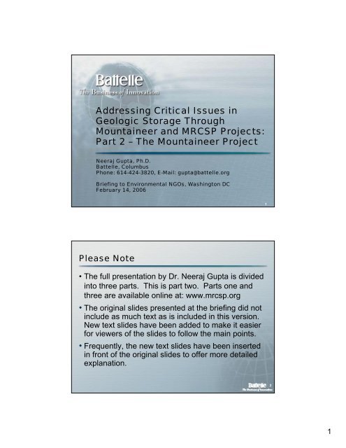
Overview of <strong>Mountaineer</strong> <strong>Project</strong> Slides• This section consists of 35 slides that address five maintopics:1. Background on the research project.2. Preliminary site characterization.3. Description of the project: well construction andresearch tests.4. Refined site characterization based on well bore testsand other research.5. Plans for additional research at <strong>Mountaineer</strong> site.1. Background2. SiteCharacterization3. <strong>Project</strong>Plan4.Findings5. FuturePlans3<strong>Mountaineer</strong> <strong>Project</strong> Background: AUnique Public Private Collaboration• Battelle – Neeraj Gupta, Joel Sminchak, Jim Dooley, Judith Bradbury, BruceSass, Prasad Saripalli, Mark Kelley, Mark White, Frank Spane, KenHumphreys, Danielle Meggyesy• DOE/NETL – Charlie Byrer, Scott Klara, and others• AEP – Mike Mudd, Dale Heydlauff, Gary Spitznogle, Charlie Powell, ChrisLong, John Massey-Norton, Jeri Matheney, Tim Mallan, et al.• Ohio Coal Development Office – Jackie Bird, Howard Johnson• BP – Charles Christopher• Schlumberger – T.S. Ramakrishnan, Nadja Mueller, and many others• Ohio Geological Survey: Larry Wickstrom• <strong>Regional</strong> Geologists: Tom Wynn, Bill Rike, John Forman, Amy Lang• Stanford’s GCEP Program – Mark Zoback, Amie Lucier• CO 2 Capture Companies• <strong>Regional</strong> Oil and Gas Companies• CRIEPI (Japan)42
<strong>Mountaineer</strong> CO 2Storage <strong>Project</strong>: KeyMotivations• A large number of CO 2sources lie in the Ohio River Valley region and it isimportant to determine the CO 2storage opportunities in this region.• Potential geologic storage reservoirs in deep basins are poorly characterized.• Systematic field tests and regional geologic data are essential forunderstanding storage potential and building stakeholder confidence.• <strong>The</strong> objective of this project is to characterize the CO 2storage potential anddemonstrate safe and cost effective storage at a coal-fired power plant.• We are now working on site design and permitting feasibility aspects:– Development of a capture and local transport system design– Design for injection and monitoring systems– NEPA and Underground Injection Permitting documents– Enhancing regional geologic framework development– Building on the foundation of stakeholder outreach.5<strong>Mountaineer</strong> Site Location• New Haven, West Virginia• 1300 MW Coal Power Plant63
Preliminary Site Characterization• In the <strong>Midwest</strong> region, Mt. Simon Sandstone is the most prominent CO 2injection candidate formation with estimated storage capacity exceeding100 billion tonnes of CO 2 .• Mt. Simon was one of the initial candidates for <strong>Mountaineer</strong> site.However, in the deep basins such as the Appalachian Basin, it becomesthin and has low porosity.• In addition, formations, such as Rose Run Sandstone and CopperDolomite have potential for large-scale storage in the Appalachian Basin.• <strong>The</strong> region has significant shale and other cap rock and there is no majorfaulting in the rock structure.• <strong>The</strong> <strong>Mountaineer</strong> site is located above the three formations of interest.• Seismic testing was used to further characterize the area around theproposed well. This yielded information about the layers of rocksurrounding the well.7<strong>Regional</strong> Geology• Thick sequences of sedimentary rock formbroad basins and arches in <strong>Midwest</strong>• Site located in Appalachian Basin•No other deep wellswithin 20 miles•AEP#1 = ”wildcat well”84
Surface Seismic Survey• Approx. 11 miles of 2-D seismic data collected intwo transects through well site (and across the OhioRiver)• Data processed and interpreted9<strong>Mountaineer</strong> <strong>Project</strong>: Seismic DataThis image showsthe various rocklayers that could beaccessed by theinjection well.It also shows nomajor faulting in thearea.5-6 miles105
<strong>Project</strong> Design: Well ConstructionSpecifications• <strong>The</strong> following diagram shows a map of the geologyin the area where the well was constructed and alsoa scale drawing of the well showing the level ofcasings surrounding the well bore at various depths.• Injection wells are designed to withstand injectionpressure and to provide a seal that prevents injectedCO 2 from leaking back through the well itself.Reinforced cements and other materials are used tocreate this seal.• <strong>The</strong> photographs on the right show drill bits anddevices to collect core samples of the rock in thewell bore.11Well Construction Specifications126
<strong>Mountaineer</strong> <strong>Project</strong>: Well Construction• <strong>The</strong> research team hired a well drilling team toconstruct the well at the <strong>Mountaineer</strong> site.• As the following slides depict, the team brought adrilling rig onsite for a period of about 70 days to drillthe well.• When the team finished drilling they removed the rigand put a small well head in place.13Well Construction147
Well Construction15Characterization and Sampling in theWell• Slide 17 shows an example of the wireline toolsused to characterize the geologic layers and obtainbrine samples from discrete zones. <strong>The</strong> wirelinelogs can tell us about the rock types, mineralogy,rock porosity, permeability etc.• Slide 18 shows some of the rock core samplesrecovered from the wells at depths greater than7,000 ft and the relative location of the samples inthe borehole rock layers.168
Down Well Logging17<strong>Mountaineer</strong> <strong>Project</strong>: Data InterpretationExtensiveConfining Layers(“Caprock”)Target Storage FormationsRose Run Sandstone andCopper Ridge B-zone189
Reservoir Tests and Brine Analysis• Packer tests used to determineformation properties and maximumallowable injection pressures inseveral zones.• <strong>The</strong> properties match with those ofwireline logs and core analysis.• Testing during fall 2005 confirmsthat transmissivity of Copper RidgeB zone is several times greater thanthe Rose Run.• At this site, Mt. Simon does nothave sufficient permeability, butregionally it is still the largestcandidate.• Geomechanical data has beenused by Stanford to evaluatestability of lateral wells and in-situstress analysis.Downhole Pressure, MPa55DataBorehole: AEP #1Static TrendFormation: Rose Run54Test Depth: 2,356 - 2,400 mSimulation Match53522514503Events11 = Slug/DST492 = DST Recovery3 = Constant Drawdown4 = Constant-DD Recovery4848 53 58Time, hr (to = 1312 hr; 3/17/04)19Synthesizing the Findings• In the <strong>Midwest</strong> region Mt. Simon Sandstone is the mostprominent CO 2 injection candidate formation with estimatedstorage capacity exceeding 100 billion tonnes of CO 2 .• Mt. Simon was one of the initial candidates for <strong>Mountaineer</strong>site too. However, in the deep basins such as theAppalachian Basin, it becomes thin and has low porosity.• Confirmation of this anticipated lack of injectivity in thiszone at <strong>Mountaineer</strong> had created a misperception thatthe entire site does not have good injectivity.• Formations, such as Rose Run Sandstone have potential forlarge-scale storage in the Appalachian Basin and this hasbeen validated at <strong>Mountaineer</strong> through testing and modeling.• <strong>Regional</strong>ly, Mt. Simon remains the most importantstorage reservoir in much of Ohio, Michigan, Indiana etc.2010
CO 2Injectivity in the <strong>Mountaineer</strong> Area• A number of geologic formations have been evaluated for CO 2 storagepotential in the Ohio River Valley region, as shown for <strong>Mountaineer</strong> sitebelowCO 2 injection should also bepossible in shallower sandstoneand carbonate layers in the regionRose Run Sandstone (~7800 feet)is a regional candidate zone inAppalachian BasinA high permeability zone called the“B zone” within Copper RidgeDolomite has been identified as anew injection zone in the regionMount Simon Sandstone/BasalSand - the most prominentreservoir in most of the <strong>Midwest</strong>21Rose Run Sandstone Core Analysis – GoodPotential Storage ZoneRose Run Sandstone 7755-7871 ftThin Section 7775 ftWireline Log 7700-7900 7900 ftFull Rock Core 7772-77827782FeetNote: fractures shown result of core collection.X100Hydraulic Core Tests 7775 ftLithology = SandstoneDensity = 2.64 g/mLPorosity = 10.4%Permeability = 49 mD• BP has recently completed state-of-the-art CO 2 relativepermeability analysis on these samples as part of theirsponsorship of the project.Shows Sandstone-Dolomite LithologyShows Sandstone-Dolomite LithologyShows Lower Density and Hihger Porosity2211
<strong>Mountaineer</strong> <strong>Project</strong>: Data Findings• Initial modeling suggests several hundred kilo-tons/yrCO 2 injection possible in single well (plant emits 7-8million tones per year). <strong>The</strong> modeling results need tobe verified through field injection tests.23Beekmantown Dolomite – Immediate OverlyingCaprockRotary Sidewall Core 7275 ftBeekmantown Dolomite 7210-7755 ftThin Section 7275 ftWireline Log 7100-7300 7300 ftFeet0 2 4 cmX100Hydraulic Core Tests 7275 ftLithology = DolomiteDensity = 2.82 g/mLPorosity = 0.38%Permeability =
Lower Copper Ridge Dolomite –A New Storage Candidate Identified• Rocks under Rose Rundominated by dense dolomite(carbonate) layers.• However, storage potential wasobserved in part of Copper RidgeDolomite (B-Zone at 8100-8300 ftdepth) based on NMR testing.• This has also been validatedthrough detailed stress tests inAEP well, which show that thiszone may even have higherinjectivity than the Rose Run.• Similar high permeability zoneobserved in several wells,including one near Gavin plant.This is promising for regionalstorage potential.25Potential Future ResearchSubject to funding and permitting• Select injection well design.• Install injection well.• Install monitoring well.• Install surface capture/injectionsystem.• Perform injection test.• Pre- and post-injection monitoring.2613
Environmental AssessmentOhio River Valley <strong>Carbon</strong> DioxideCapture and Storage <strong>Project</strong>3.5 No-action Alternative4.0 Affected Environment and <strong>Project</strong> Description7.0 Environmentally Preferred Alternative9.0 Public Participation3.2 Proposed Action3.5 No-action Alternative7.0 Environmentally Preferred AlternativeEnvironmental AssessmentOhio River Valley <strong>Carbon</strong> DioxideEnvironmental AssessmentCO 2Source and Surface Completion(Subject to Funding and Permitting)•Create capturesystem forslipstream fromexisting plant27<strong>Mountaineer</strong> Regulatory Documents:(Subject to Funding and Sponsors’ Agreement)• A NEPA Environmental Assessment would covercapture, pipeline transport, injection, and long-termstorage for the potential future phase at the<strong>Mountaineer</strong> site.• USEPA Class V UIC Permit is under development,to be submitted to West Virginia Department ofEnvironmental Protection, if decided by AEP andDOE.UIC Area of Review3.2 KM (2-miles)0.7 kmAEP#1Pilot Demonstration, <strong>Mountaineer</strong> Power Plant,New Haven, West Virginia1.0 Introduction2.0 Purpose and Need for Action3.0 Alternatives, Including the Proposed Action3.1 Overview3.2 Proposed ActionCapture and Storage <strong>Project</strong>Pilot Demonstration, <strong>Mountaineer</strong> Power Plant,New Haven, West Virginia1.0 Introduction2.0 Purpose and Need for Action3.0 Alternatives, Including the Proposed Action3.1 OverviewOhio River Valley <strong>Carbon</strong> DioxideCapture and Storage <strong>Project</strong>Pilot Demonstration, <strong>Mountaineer</strong> Power Plant,New Haven, West Virginia1.0 Introduction2.0 Purpose and Need for Action3.0 Alternatives, Including the Proposed ActionAEP#1 Test WellOil and Gas WellArea of ReviewSCALE (MILES)0 1 2 3All Locations Approximate3.2 Proposed Action3.3 Alternative Action 1- Alternate Injection Location/Facility3.1 Overview3.3 Alternative Action 1- Alternate Injection Location/Facility3.4 Alternative Action 2- Alternate CO2 Mitigation Technologies3.4 Alternative Action 2- Alternate CO2 Mitigation Technologies3.3 Alternative Action 1- Alternate Injection Location/Facility3.4 Alternative Action 2- Alternate CO2 Mitigation Technologies4.0 Affected Environment and <strong>Project</strong> Description5.0 Environmental Consequences3.5 No-action Alternative5.0 Environmental Consequences6.0 Irreversible and Irretrievable Commitments of Resources4.0 Affected Environment and <strong>Project</strong> Description6.0 Irreversible and Irretrievable Commitments of Resources5.0 Environmental Consequences8.0 Compliance with Applicable Regulations, Policies, and Permits6.0 Irreversible and Irretrievable Commitments of Resources8.0 Compliance with Applicable Regulations, Policies, and Permits7.0 Environmentally Preferred Alternative9.0 Public Participation10.0 References8.0 Compliance with Applicable Regulations, Policies, and Permits10.0 References9.0 Public Participation10.0 ReferencesGeologic cross section showingwell depths near AEP#1 (in blue).2814
<strong>Mountaineer</strong> <strong>Project</strong>: StakeholderOutreach to be Continued(Subject to Funding and Sponsors’ Agreement)• Numerous meetings by Battelle and AEP personnel to inform keystakeholders about the project:– Plant managers and employees at and near the power plant– <strong>Regional</strong> and national non-governmental organizations (NGOs): NGOworkshop in January 2004 and February 2006.– Local and state officials – mayors, county commissioners, state legislators– Federal Officials - senators andCongressmen.– State PSC, Development Office,Energy Task Force.– State DEP and EPA officials(EPA Workshop).– Numerous scientific meetingsand workshops.29Potential Injection Test(Subject to Funding and Permitting)•Injection of 30-100 metrictons CO 2 /day in Rose RunSS and/or Copper Ridge.•Avg 7.8 gpm•2-5 years of continuousinjection.•Entire system will becontained on plant site.3015
Monitoring(Subject to Funding and Permitting)• Monitoring of system considered critical step inensuring safe, effective, and long-term operation.• Necessary for stakeholder acceptance (i.e. AEP,plant personnel, local residents, NGOs, localresidents).• Many analogues for gas storage (natural gasstorage, hazardous waste injection, natural CO 2fields).31“Layered Monitoring Objectives”(Subject to Funding and Permitting)•Injection/Capture System•Operational Safety•Leakage•Injected CO23216
Example Survey of CO 2 Monitoring Methods for<strong>Mountaineer</strong>MethodInjectionSystemFluidphaseGas-PhaseWirelineorDown-wellDescriptionInjection WellMeasurementsShallow GW MonitoringSurface water samplingReservoir SamplingMonitoring injectateTracers in injectateShallow soil-gas monitoringLower atmosphericmonitoringTraditional WirelineRSTDSISuitability+++++--++++++----++++++++CommentsBasic parameters required for UIC permit, but a full suite ofmethods not required for Class V.Reservoir too deep to produce a detectable signature in shallowaquifers. Relatively inexpensive to perform. Required forUIC permit.Reservoir too deep to produce a detectable signature atsurface. Relatively inexpensive to perform.May be expensive to collect quality samples given reservoirdepths.Required for UIC permit, probably included incapture/separation program.More applicable to reservoir in a established well-field withnumerous monitoring wells in-place. Would requireextensive sampling to detect “break-through.” Possible thatsingle well would miss slug.Reservoir too deep to produce a detectable signature atsurface. Relatively inexpensive, some risk of backgroundCO2 levels affecting results.Reservoir too deep to produce a detectable signature atsurface. Relatively inexpensive, some risk of backgroundCO2 levels affecting results.Readily available, may be used in injection well or monitoringwell.Proven method, may be used in injection well or monitoringwell.Proven method, may be used in injection well or monitoringwell.33Suitability of CO 2 Monitoring Methods for<strong>Mountaineer</strong>MethodOtherGeophysicalDescription4-D SeismicVSPMicroseismicCrosswell SeismicTomographySuitability++++CommentsResolution of survey too low to detect CO2 in reservoirsHigh velocities in reservoir rocks may make it difficult todetect density contrast due to presence of CO2High background “noise” would require installation ofgeophones in bedrock wells several hundred feet deep.Continuous monitoring schedule.More applicable to reservoir in a established well-field withnumerous monitoring wells in-place, high velocities inreservoir rock.ERT/EMT+More applicable to reservoir in a established well-field withnumerous monitoring wells in-place. Somewhatexperimental.RemoteSensingAirborne gasAeromagnetics/GravityHyperspectral imagerySurface deformation/tilt---------+Reservoir too deep to produce a detectable signature,relatively small injection volume not likely to requireairborne survey.Reservoir too deep to produce a detectable signature,relatively small injection volume not likely to requireairborne survey.Reservoir too deep to produce a detectable signature,relatively small injection volume not likely to requireairborne survey.Injection unlikely to deform surface given reservoir depth.Sight level/tilt meter could be included with surfacemonitoring at low cost.3417
<strong>Mountaineer</strong> <strong>Project</strong> Summary: Progressin a Phased Manner• A detailed site-characterization effort has been completed.• Local and regional characterization is the most important aspect forplanning successful projects.• Substantial improvement in understanding features of relevant geologicformations in <strong>Midwest</strong>ern USA with applicability to other mature basins.• New storage reservoirs have been identified and their injection potentialquantified.• Continuing progress to initiate a first-of-a-kind integrated demonstration ofcapture, local transport, storage, and monitoring test at a major powerplant.• Collaboration with the oil and gas industry (local small independentproducer) is critical for cost effective regional reservoir characterization.• Joint industry-government R&D efforts to secure a future for fossil fuelsand secure a future for region’s fossil-fired generation fleet in agreenhouse gas constrained world are essential.3518