Create successful ePaper yourself
Turn your PDF publications into a flip-book with our unique Google optimized e-Paper software.
CAUTION! This product uses LASER RA-DIATION for measurements. DO NOTSTARE INTO BEAM.Refer to these laser safety statementswhenever this sign is displayed.Peak power 1.0 mW.Pulse durati<strong>on</strong> 5 m sec.Emitted wavelength 650nm.Class II laser product. Cauti<strong>on</strong> - the use ofoptical instruments with this product willincrease risk of eye hazard.WARNING!!! DO NOT STARE INTO LA-SER BEAM! EYE INJURY MAY OCCURWITH PROLONGED EYE CONTACTWITH LASER. AVOID EYE CONTACTWITH THE LASER SCANNERSWARNING!!! IN THE EVENT OF MA-CHINE MALFUNCTION, DO NOT LOOKINTO THE LASER AREA. PROLONGEDEXPOSURE TO THE LASER MAYCAUSE EYE INJURY.PERFORM REGULAR CLEANING OF THELASER SCANNER GLASS TO ENSUREOPTIMUM OPERATION.DO NOT KNOCK OR TAMPER WITH THELASER SCANNERSCAUTION! - Use of C<strong>on</strong>trols or adjustmentsor performance of procedures other thanthose specified herein may result in hazardousradiati<strong>on</strong> exposure.ALWAYS OPERATE THE WHEEL BAL-ANCER WITHIN THE RANGES STATED INTHE LABEL SHOWN BELOW.WARNING!!!SEVERE PERSONAL IN-JURY WILL OCCUR IF FINGERS ORHAND IS PINCHED BETWEEN THECLAMP NUT, WHEEL OR FLANGEIII
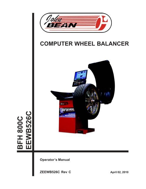
John Bean BFH 800 Operators Manual1.0 INTRODUCTIONC<strong>on</strong>gratulati<strong>on</strong>s <strong>on</strong> purchasing the BFH 800 Computer Wheel Balancer. This wheel balancer is designed for easeof operati<strong>on</strong>, accuracy, reliability and speed. With proper maintenance and care your wheel balancer will providemany years of trouble-free operati<strong>on</strong>.BFH 800 Computer Wheel Balancer - Precauti<strong>on</strong>s To ObserveYour BFH 800 Balancer utilizes the latest in electr<strong>on</strong>ics and instrumentati<strong>on</strong> technology, incorporating two separatescanning lasers al<strong>on</strong>g with an embedded computer (PC). Following the precauti<strong>on</strong>s listed below will help toensure c<strong>on</strong>tinuous and satisfactory operati<strong>on</strong> of your unit.1) Install the balancer <strong>on</strong> a dedicated power line in order to avoid electrical noise and power line fluctuati<strong>on</strong>s. Avoidpower cord length greater that 15 feet.2) The BFH 800 Wheel Balancer utilizes a red scanning laser which actually create an image of the wheel beingserviced. Install the balancer away from direct sunlight so that the laser can be detected by the scanner . Avoidplacing high intensity lamps and infrared heaters near the BFH balancer .3) Profile and balance <strong>on</strong>ly those wheels which fit within the specificati<strong>on</strong>s of the BFH Balancer:Rim width = 3 - 20 inchesRim diameter = 8 - 30 inchesMax tire diameter = 44 inchesMinimum distance required from cabinet to rim edge = 56 mm (2.20 inches) for wheel sizes 13-18 inches indiameter.Minimum distance required from cabinet to rim edge = 81 mm (3.19 inches) for wheel sizes 19-24 inches indiameter.4) The BFH balancer is designed to properly scan the profile of existing rims. Extreme geometric combinati<strong>on</strong>s ofrim diameter and flange offset can inhibit the proper viewing of the rim profile. These excepti<strong>on</strong>al rims can beproperly balanced by manually entering the distance, diameter, and width of the rim.5) The wheel guard of the BFH 800 Wheel Balancer also serves as the housing for s<strong>on</strong>ic transducer . Since thetransducer must remain stati<strong>on</strong>ary <strong>on</strong>ce the spin cycle begins, do not lean <strong>on</strong> or otherwise disturb the wheelguard until the spin cycle has been completed.Instructi<strong>on</strong>s <strong>on</strong> use, operati<strong>on</strong>al requirements and routine maintenance of the machine are covered in this manual.This unit uses an open source Linux operating system for its user interface. This open source code is availablefor the cost of shipping and handling to owners of the BFH 800 Wheel Balancer. Request s must be made to theattenti<strong>on</strong> of balancer product management at the C<strong>on</strong>way AR address listed <strong>on</strong> the back of this manual. Pleaseinclude the owners name, address and unit serial number with all requests.1.1 SAFETY NOTICESTORE THIS MANUAL IN A SAFE PLACE FOR FUTURE REFERENCE.READ THIS MANUAL THOROUGHLY BEFORE USING THE MACHINE.This manual is a part of the balancer product. Read carefully all warnings and instructi<strong>on</strong>s of this manual since theyprovide important informati<strong>on</strong> c<strong>on</strong>cerning safety and maintenance.Page 1
1.2 BALANCER APPLICATIONThe John Bean BFH 800 Computer Wheel Balancer is intended to be used as a device to correct imbalance andcorrect car, and light truck wheel vibrati<strong>on</strong> problems within the following range:Maximum tire diameter : 44” (1117mm) Maximum wheel diameter: 30” (762mm)Maximum wheel width : 20” (381mm) Maximum wheel weight : 154 lbs (70 kg)This device is to be <strong>on</strong>ly used in the applicati<strong>on</strong> for which it is specifically designed.Any other use shall be c<strong>on</strong>sidered as improper and thus not reas<strong>on</strong>able.The manufacturer shall not be c<strong>on</strong>sidered liable for possible damages caused by improper, wr<strong>on</strong>g or n<strong>on</strong> reas<strong>on</strong>ableuse.1.3 BFH 800 SPECIFICATIONSWeight Imbalance Accuracy.05 oz / 1 gramWeight Placement Resoluti<strong>on</strong>± .7 degreesWeight Imbalance Resoluti<strong>on</strong>:Roundoff Mode.25 oz / 5 gramsN<strong>on</strong>-Roundoff Mode.05 oz / 1 gramMax. Shaft Weight Capacity154 lbs / 70 kgMax.Tire Diameter44" / 1117 mmRim Width Capacity3.0"-20" / 76 mm - 508 mmMax. Tire Width21” / 530 mmRim Diameter Capacity8"-30"/203mm-762mmBalancing Cycle Time.20 sec<strong>on</strong>ds or lessShaft Speed at calculati<strong>on</strong> 200 RPMElectrical 230vac, 1ph, 50-60Hz, 3.2ARequired Work Area64” x 64” (1626 x1626 mm)Shipping Weight, complete645 lbs/293kgShipping Dimensi<strong>on</strong>s72"L X 73"W X 63"D (1829x1854x1600mm)Machine Dimensi<strong>on</strong>s64”h 64”w 64”d (1626x1626x1626mm)Actual Weight with Accessories550 lbsOperating Temperature Range 32-122F / 0-50C1.4 FEATURES• Self test check with every power up cycle.• Pre-programmed Error Codes indicate procedural errors or safety c<strong>on</strong>cerns.• Fully Automatic All-Parameter Data Entry.• Fully Automatic Rim Profiling.• Opti<strong>on</strong>al Weight Miser and Weight Wizard software• Fully Automatic Spoke/Split Weight Functi<strong>on</strong> for Hidden Weight Placement.• Hands-Free Power Clamping for Precise Wheel Placement.• Captured back spring eliminates having to handle the backing spring.• Automatic recalculati<strong>on</strong> if weight positi<strong>on</strong>s are changed. No need for re-spinning the wheel.• Comm<strong>on</strong> 40 mm diameter mounting shaft.• Easy-to-Read LCD Data Display M<strong>on</strong>itor.• Dynamic and single weight Static capability.• Stop-at-Top features simplifies weight imbalance locati<strong>on</strong>• Automatic Weight Type Selecti<strong>on</strong> Based <strong>on</strong> Rim Profile, Indicated by Color Coded Ic<strong>on</strong>s• Built-in spin counter for m<strong>on</strong>itoring balancer productivity.• Service code access to all Balancer electr<strong>on</strong>ic functi<strong>on</strong>s for fast, easy diagnosis.• Operator selectable roundoff mode.Page 2
John Bean BFH 800 Operators Manual1.5 STANDARD ACCESSORIES1.6 OPTIONAL ACCESSORIESStandard accessories ( Figures 1, 2, and 3,) includedwith the BFH 800 are:1 EAM0005D40A Weight - Calibrati<strong>on</strong>2 EAC0060G02A Flange - Cover, Hook3 EAM0006G01A Pin - Accessory4 58839 Weight Pliers5 EAA0247G21A Caliper - Rim Width6 EAA0283D53A Power Clamp NutPower Clamp Nut Accessories:A EAC0058D15A Soft Protective RingB EAC0058D07A Cup - Large PressureD EAM0005D54A Plastic SleeveE EAC0058D08A Small Presure Disk4 PC C<strong>on</strong>e Kit, p/n EAK0221J60A, c<strong>on</strong>tains:A EAM0003J08A C<strong>on</strong>e, 85-132 mm / 3.3”-5.2”B EAM0003J07A C<strong>on</strong>e, 71-99 mm / 2.8”-3.9”C EAM0003J06A C<strong>on</strong>e, 56-84 mm / 2.2”-3.3”D EAM0003J05A C<strong>on</strong>e, 43-63 mm / 1.7” - 2.5”7PC C<strong>on</strong>e Kit, p/n EAK0221J31A, c<strong>on</strong>tains:A EAM0003J64 C<strong>on</strong>e 1.70" T0 2.23"B EAM0003J65 C<strong>on</strong>e 2.03" T0 3.17"C EAM0003J66 C<strong>on</strong>e 2.38" T0 3.51"D EAM0003J67 C<strong>on</strong>e 2.74" T0 3.87"E EAM0003J68 C<strong>on</strong>e 3.08" T0 4.21"F EAM0003J69 C<strong>on</strong>e 3.42" T0 5.40"G EAM0003J70 C<strong>on</strong>e 4.21" T0 6.30"Figure 1- Standard AccessoriesFigure 2 - Power Clamp Nut AccessoriesPage 3
NOT SHOWN:Unilug adapter kit - pn 10614Truck c<strong>on</strong>e kit - pn 110612Motorcycle adaptor kit - pn - EAA0260D80Aand the below pictured opti<strong>on</strong>s:Figure 4 - Opti<strong>on</strong>al AccessoriesStick-<strong>on</strong> Weight Removal Tool Flange Plates - Kit of 4 Flange Plate CartEEHT300A EAK0221J22A EAS2081J30APRE-INSTALLATION CONSIDERATIONS1.7 DIMENSIONS OF THE MACHINEFigure 5 - Footprint Requirements1.8 INSTALLATION AREA REQUIREMENTSMake sure that from the operating positi<strong>on</strong> the user can see all of the machine and the surrounding area.The operator should prevent n<strong>on</strong> authorized pers<strong>on</strong>s and/or objects from entering the area which may createpotential hazards.The machine should be installed <strong>on</strong> a stable level floor. Do not install the machine <strong>on</strong> a uneven floor .If the balancer is to be installed <strong>on</strong> a raised floor, the floor must have a capacity of at least 110lbs per sq ft. (5000N/m² - 500 kg/m²).It is not required to secure the machine to the floor but is recommended.Install the machine in a dry, covered area.The installati<strong>on</strong> of the machine requires a working area of at least 64” x 64” (1626 x1626 mm) . See Figure 5Page 4
John Bean BFH 800 Operators Manual1.9 INSTALLATION PRECAUTIONSCAUTION! CAREFULLY REMOVE THE BALANCER FROM THE PALLET.Remove the hardware that secures the machine to the pallet and slide the balancer <strong>on</strong>to the floor where it is tobe installed.THE UNIT IS HEAVY AND THE WEIGHT IS NOT EVENLY DISTRIBUTED.DO NOT LIFT THE BALANCER BY THE SHAFT OR WHEEL GUARD FRAME.DROPPING THE UNIT MAY CAUSE PERSONAL INJURY OR EQUIPMENT DAMAGE.2.0 INSTALL ACCESSORY PINSA. Install the accessory pins (Figure 6). Tighten firmly.Figure 6B. Place accessories <strong>on</strong>to the accessory pins.2.1 INSTALLATION OF THE HOOD GUARD2.1.1 Place the hood guard frame <strong>on</strong>to the pivot tube. Line up the holes in both frame and pivot, insert bolt.Secure using the supplied nut in the down positi<strong>on</strong>.2.1.2 C<strong>on</strong>nect the s<strong>on</strong>ic transducer cable to short cable <strong>on</strong> the rear of the cabinet.2.1.3 Pivot the frame up and down carefully and make sure the guard moves freely , the cable does not bind andthe guard does not fall by itself.2.2 MONITOR INSTALLATIONBeginning early December 2008 Wheel Balancers utilizing a flat panel m<strong>on</strong>itor will be provided with a universalVESA video adapter bracket for mounting of the flat panel m<strong>on</strong>itors.Mounting c<strong>on</strong>figurati<strong>on</strong> may vary depending up<strong>on</strong> thesupplied m<strong>on</strong>itor model. See the descripti<strong>on</strong> below forinstructi<strong>on</strong>sHOW TO ASSEMBLE1. Remove the m<strong>on</strong>itor factory installed base assemblyso the bare m<strong>on</strong>itor remains, see Figure 7. Some flatpanel m<strong>on</strong>itors may have a plastic cover over the factorybase. To remove the plastic base cover insert a flatblade screwdriver under <strong>on</strong>e corner of the base cover andpry gently until the cover releases.Figure 7Page 5
2. Remove the base by removing the four phillips screws.Secure the screws if desired. See Figure 8.Figure 83. Locate the VESA m<strong>on</strong>itor bracket and orientate as shown in Figure 9.4. Using the supplied hardware, Loosely secure theVESA bracket to the m<strong>on</strong>itor. Once all four screws areinserted tighten firmly being sure to avoid overtightening.NOTE: Some m<strong>on</strong>itors may have 75mm x 75mmc<strong>on</strong>figurati<strong>on</strong>s while others may have 100mm x 100mmc<strong>on</strong>figurati<strong>on</strong>s. Select what is appropriate for thesupplied m<strong>on</strong>itor.5. C<strong>on</strong>nect the Video and power cables to the m<strong>on</strong>itor.6. Secure the m<strong>on</strong>itor-bracket assembly to the towersupport using the lower pivot screw hole.NOTE: Some m<strong>on</strong>itors may use <strong>on</strong>e of the remainingpivot holes in the future. Use your best judgment whenselecting the proper pivot hole.Figure 92.3 ELECTRIC INSTALLATIONANY ELECTRICAL WIRING MUST BE PERFORMED BY LICENSED PERSONNEL.ALL SERVICE MUST BE PERFORMED BY AN AUTHORIZED SERVICE TECHNICIAN.Check <strong>on</strong> the plate of the machine that the electrical specificati<strong>on</strong>s of the power source are the same asthe machine. The machine uses 230VAC (+/- 15%), 50-60Hz, 1Ph, 3.2 Ampere.NOTE: ANY ELECTRICAL OUTLET INSTALLATION MUST BE VERIFIED BY A LICENSED ELECTRICIANBEFORE CONNECTING THE BALANCER.NOTE: THIS MACHINE PERFORMS A SELF-TEST ROUTINE ON START-UP. THERE WILL BE A DELAY OFSEVERAL MOMENTS BEFORE UNIT IS READY FOR OPERATION. ANY PROBLEMS DETECTED ATSTART-UP WILL RESULT IN THE DISPLAY OF AN ERROR CODE. PROBLEMS DETECTED DURINGOPERATION ARE SAVED TO A LOG FILE WHICH CAN BE RETRIEVED FOR DIAGNOSIS BY A TECH-NICIAN.Page 6
John Bean BFH 800 Operators Manual2.4 SETUPEvery shop has different procedural requirements meaning each machine should be customized to theunique services performed at that locati<strong>on</strong>. Most attributes are set from the Main Functi<strong>on</strong> menu.2.4.1 Customizing the SystemA. Select the “Functi<strong>on</strong>” key (F1) from the “Welcome” menu. The Main Functi<strong>on</strong> setup screen appears as inFigure 10 as show <strong>on</strong> next page.B. Press and hold the “F6” butt<strong>on</strong> and rotate the shaft to scroll up or down to the desired line item.C. Press and hold the “F5” butt<strong>on</strong> and rotate the wheel to change selected topic to desired value or functi<strong>on</strong>.D. When the desired features have been selected, save selecti<strong>on</strong>s to permanent memory by selecting lineitem “3”. Hold the F5 butt<strong>on</strong> while rotating the shaft, enter a value of “1”, release Save to to PermanentMemory.E. Select the “ESC” butt<strong>on</strong> <strong>on</strong> the keyboard to return to the main screen.Page 7
Page 8Figure 10
John Bean BFH 800 Operators Manual6117231893.0 PHYSICAL LAYOUTRefer to Figure 11. - Functi<strong>on</strong>al descripti<strong>on</strong> of the unit:1. The screen2. Input panel3. Gauge arm4. Stub shaft with power clamp nut5. Brake pedal6. Weight compartments7. Storage areas for c<strong>on</strong>es or clampingdevices8. Tilting frame and hood guard9. S<strong>on</strong>ic Transducer10. Inner scanner10543.1 The Display ScreenSee Figure12, Screen with display fieldsFigure 1171-5 Informati<strong>on</strong> fields6 Menu fields and Functi<strong>on</strong> descriptors.7 Display field of screenThe screen reads out input s, helpful informati<strong>on</strong>,all measured data and error codes.12345Figure 126Detailed descripti<strong>on</strong> of display fieldsThe screen is subdivided into various display fields, eachof which is associated with a certain type of informati<strong>on</strong>.Informati<strong>on</strong> fields1 Number of the installed program versi<strong>on</strong>Machine nameDate and time2 Selected Menu name3 Selected profiling mode4 Electrical compensati<strong>on</strong>5 Error codes6 Menu fieldsIc<strong>on</strong>s illustrating special features or functi<strong>on</strong>s areviewed in the six menu fields. Under every menufield is the associated menu “F key” which is usedto call the feature illustrated.7 Display fieldWheel type and rim dimensi<strong>on</strong>sBalancing modesAmount of unbalanceDirecti<strong>on</strong> of orientati<strong>on</strong> and correcti<strong>on</strong> positi<strong>on</strong>Functi<strong>on</strong> and Setup MenusPage 9
3.2 Menu Keys3.2.1 Descripti<strong>on</strong> of Menu KeysThe assignment of the menu keys F1 to F6 is shownin the menu fields above the relative keys <strong>on</strong> thescreen. The menu keys have different functi<strong>on</strong>s andinitiate different acti<strong>on</strong>s, depending <strong>on</strong> the programstep.- Keys without a symbol in the upper right-hand corneror at the edge initiate an acti<strong>on</strong> immediately, suchas F2 <strong>on</strong> the main screen means to perform acompensati<strong>on</strong> process. See Figure 13.- Keys with <strong>on</strong>e or more symbols in the upper righthandcorner of the menu field or at the edgesinitiate various acti<strong>on</strong>s:Figure 13a - Press key to access a sub-menu, e.g. key F 4Balancing.b - Press and hold key down while rotating wheel atsame time, e.g. key F11 Number of spokes.c - Press key to toggle between two opti<strong>on</strong>s or st ates,e.g. key F9 Static / dynamic unbalance.abcdd - Press key to toggle between several opti<strong>on</strong>s orstates, e.g. key F 21 Weight positi<strong>on</strong> for correcti<strong>on</strong>plane.e - Toggle switch (4 functi<strong>on</strong>s): Press edge of key tocarry out the highlighted acti<strong>on</strong>, e.g. key F 32Character set: move the cursor in the character setto the left, to the right, up or down.eff - Toggle switch (2 functi<strong>on</strong>s): Press key <strong>on</strong> top orbottom to select the highlighted functi<strong>on</strong>, e.g. key F8Precisi<strong>on</strong> reading of unbalance and mode select.Page 10
John Bean BFH 800 Operators Manual3.2.2 MAIN MENU FUNCTIONSIc<strong>on</strong> 1 Change to the Functi<strong>on</strong> screenIc<strong>on</strong> 2 Perform adapter compensati<strong>on</strong> runIc<strong>on</strong> 1 Ic<strong>on</strong> 2Ic<strong>on</strong> 3 Change to the Balancing screenIc<strong>on</strong> 33.2.3 BALANCINGIc<strong>on</strong> 5 Toggle switch, two functi<strong>on</strong>s:Pressed <strong>on</strong> top:View and/or edit Data Input (wheel parameters)Ic<strong>on</strong> 5 Ic<strong>on</strong> 6Pressed <strong>on</strong> bottom:Move the laser positi<strong>on</strong> pointer to the desiredlocati<strong>on</strong>. Butt<strong>on</strong> must be held down as the shaft isrotated. (<strong>on</strong>ly when stick-<strong>on</strong> weights are selected)Ic<strong>on</strong> 7aIc<strong>on</strong> 7bIc<strong>on</strong> 6 Toggle switch, two functi<strong>on</strong>s; reading <strong>on</strong>ly asl<strong>on</strong>g as the key is pressed (quick reading):Pressed <strong>on</strong> top:Precisi<strong>on</strong> reading of unbalance, no suppressi<strong>on</strong> ofminor unbalance readings.Pressed <strong>on</strong> bottom:Toggles through possible placement locati<strong>on</strong>s ofweight placement for c<strong>on</strong>venti<strong>on</strong>al balancing run.Ic<strong>on</strong>s 7a and 7b Select st atic unbalance or Selectdynamic unbalanceIc<strong>on</strong> 8 Number of spokes has been selected andentered.Ic<strong>on</strong> 8 Ic<strong>on</strong> 9Ic<strong>on</strong> 10Ic<strong>on</strong> 9 Number of spokes has not been detected.1. Press and hold F5 and turn the wheel to enter the numberof spokes.2. Release F5 when the right number of spokes is indicated.3. Turn the wheel in the way that <strong>on</strong>e spoke is located <strong>on</strong> the12 o´clock positi<strong>on</strong>.4. Press F5 and the balancer will split the weight into 2 pieces.5. Place the weights behind the spokes.Ic<strong>on</strong> 10 Wheel with 6 spokes selectedPage 11
3.2.4 RIM DATA INPUTIc<strong>on</strong> 11 Change to the WEIGHTPLACEMENT (mode)screen.Ic<strong>on</strong> 11 Ic<strong>on</strong> 12Ic<strong>on</strong> 12 Change to the RIM TYPE screenIc<strong>on</strong> 13 Hold key down and enter the distmachine by rotating the wheelance rim/Ic<strong>on</strong> 14 Hold key down and enter the rim widrotating the wheelth byIc<strong>on</strong> 13 Ic<strong>on</strong> 14Ic<strong>on</strong> 15 Hold key down and enter rim diameter byrotating the wheelIc<strong>on</strong> 16 Change to the Stored Parameter menu. Mustbe in the “Manual” parameter modeIc<strong>on</strong> 15 Ic<strong>on</strong> 163.2.5PROFILES SCREEN, STORED PARAMETERSIc<strong>on</strong> 17Ic<strong>on</strong> 18Ic<strong>on</strong> 17 Select or store a wheel profile. Hold key downand select copy or store by rotating the wheel.Ic<strong>on</strong> 18 Store a parameter. Select memory locati<strong>on</strong> tostore current wheel profile for later retrieval (yellowarrow). Select “OK” to enter the values currently in useto a stored locati<strong>on</strong>.Ic<strong>on</strong> 19 Copy a stored p arameter. Select memorylocati<strong>on</strong> for retrieval (yellow arrow). Select “OK” to enterthe values stored for use in the next balance run.Ic<strong>on</strong> 20 Accept or enter the selected parameters.Ic<strong>on</strong> 19 Ic<strong>on</strong> 203.2.6 FUNCTION MENUIc<strong>on</strong> 21 From the Main Menu, Select FUNCTION toaccess screens used to prep are the unit for desiredoperati<strong>on</strong>.Ic<strong>on</strong> 21 Ic<strong>on</strong> 22Ic<strong>on</strong> 22 Change to the screen USER CALIBRATION,see Maintenance chapter for user calibrati<strong>on</strong>procedures.Page 12
John Bean BFH 800 Operators Manual3.2.7 TEXT EDITORIc<strong>on</strong> 23 Change to the screen TEXT EDITORIc<strong>on</strong> 23 Ic<strong>on</strong> 24Ic<strong>on</strong> 24 Toggle key, four functi<strong>on</strong>s: Move the cursorwithin the character set (right, lef t, up, down) to thedesired character.Ic<strong>on</strong> 25 Toggle key, four functi<strong>on</strong>s: Move the cursorwithin the text field (right, left, up, down) to the desiredtext box locati<strong>on</strong>Ic<strong>on</strong> 26 Transfer characters from the character set tothe text fieldIc<strong>on</strong> 27 Save textIc<strong>on</strong> 25 Ic<strong>on</strong> 26Ic<strong>on</strong> 273.2.8 FUNCTION (SETUP)Ic<strong>on</strong> 28Ic<strong>on</strong> 29Ic<strong>on</strong> 28 Change selected topic to desired value orfuncti<strong>on</strong>.Ic<strong>on</strong> 29 Hold butt<strong>on</strong> and rotate the wheel to scroll up ordown to the desired line item.Setup screen illustrati<strong>on</strong>. When desired features havebeen selected, save to permanent memory by selectingline item “3”, Save to Permanent memory, enter a valueof “1” with the F5 butt<strong>on</strong> while rotating the shaft. Releasebutt<strong>on</strong> to save. Select the “ESC” butt<strong>on</strong> to return to themain screen. See Figure 14.Figure 14Page 13
4.0 Help informati<strong>on</strong>Help informati<strong>on</strong> explains the current acti<strong>on</strong> and, in thecase of an error code, provides hints for remedy. SeeFigure 15.Figure 15Display help informati<strong>on</strong>• Press the HELP key ( See Figure 16)The first screen with help informati<strong>on</strong> appears, e. g. tothe screen RIM DATA INPUT.• Press the HELP key <strong>on</strong>ce more to display anyadditi<strong>on</strong>al screen with informati<strong>on</strong>.Quit help informati<strong>on</strong>• Press the ESC keyFigure 16Page 14
John Bean BFH 800 Operators ManualPush down for brake5.0 POWER CLAMP5.1 POWER CLAMP PEDALShaft LockThe main shaft is locked when the pedal is depressed.This holds the wheel in the correcti<strong>on</strong> positi<strong>on</strong> for correctfitting of the correcti<strong>on</strong> weights. See Figure 17.This lock is designed <strong>on</strong>ly to facilitate orientati<strong>on</strong> of thewheel and must not be used for braking the main shaf t.Power Clamp Operati<strong>on</strong>.Lift upward to engage the power clamp jaws when thelock nut is placed <strong>on</strong> the shaft.Lift upward again to release the clamp nut.Lift up for power clamp operati<strong>on</strong>Figure 17NOTE: The first time the unit is operated after powerup,make sure the power clamp engaging jaws are inthe outer most positi<strong>on</strong> and ready for use. An Error of“E14” may result if the unit cannot accurately determinethe clamping jaw positi<strong>on</strong>. Simple press “ESC” toc<strong>on</strong>tinue, lift the pedal again to cycle and the powerclamp will learn its new positi<strong>on</strong>. See Figures 18 and19.Power Clamp with jaws all the way OUTFigure 18SEVERE PERSONAL INJURY WILL OCCURIF FINGERS OR HAND IS PINCHEDBETWEEN THE NUT, WHEEL OR FLANGEPower Clamp with jaws all the way INFigure 19Page 15
6.0 OPERATION OF THE BALANCERWARNING: For operator safety please read and follow the precauti<strong>on</strong>s outlined <strong>on</strong>pages 1 and 2 of this manual.NOTE: READ ALL INSTRUCTIONS BEFORE PROCEEDING WITH OPERATION OF THE BAL-ANCER.All balancer functi<strong>on</strong>s are input into the main computer through the large easy to read touch anel. p Although eachwheel tire assembly differ in some ways all balancing jobs require basically the same procedure. The order ofevents to take place are:1. Inspecti<strong>on</strong> of the wheel/tire assembly2. Mounting wheel <strong>on</strong>to shaft3. Scanner entry of wheel profile4. Applying the recommended weight5. Check spin if desired6. Dismounting the wheelThe following operati<strong>on</strong> instructi<strong>on</strong>s will follow the basic outline above.6.1 CHECK LIST - INSPECTIONObserve Before Balancing Wheel1. Check for proper air pressure. If not correct, inflate to correct pressure.2. Check for any foreign material inside tire. If present, remove before balancing tire.WATER IS FOREIGN MATERIAL!3. Remove old weights — old weights may be improper value or in wr<strong>on</strong>g locati<strong>on</strong>.4. Be sure tire and wheel are free of excessive dirt, rust and large st<strong>on</strong>es. Use wire brush <strong>on</strong> back side of wheelif necessary.Figure 205. From the main menu, see Figure 20 above, select the desired processF1. Functi<strong>on</strong> - setup the balancers parameters to perform in a certain fashi<strong>on</strong>F2. Compensate a wheel adapterF3. Select to operate in the “Opti<strong>on</strong>al Weight Miser” mode or notF4. Go to the balance process - normal selecti<strong>on</strong> for most usersF5. Not UsedF6. Optima - optimizati<strong>on</strong> processPage 16
John Bean BFH 800 Operators Manual6.2 BALANCE SCREEN DESCRIPTIONRefer to Figure 21a below for an example of a typical balance screen. The wheel displayed has beenprofiled as a rim which will accept a clip weight <strong>on</strong> the left side and a stick-<strong>on</strong> weight <strong>on</strong> the right side.The Clip weight will be placed at top dead center when the arrows indicate green. The stick-<strong>on</strong> weightis placed as indicated by the laser pointer. The operator selects the desired mode as indicated by theyellow weight ic<strong>on</strong>s, such as clip-stick as shown in the example below . Subsequent wheels will usethe same mode until a differant profile or parameter is detected.InsidePositi<strong>on</strong>IndicatorColor WeightIndicatorOutsidePositi<strong>on</strong>IndicatorInsideWeightAmountOutsideWeightAmountCurrent“FrozenData”Parameteredit menuStick weightMoveOpti<strong>on</strong>al WeightMiser ActiveMode/PlacementIndicatorsOptimizati<strong>on</strong>modeData FreezeMode Print Spoke CountMode/PlacementSelecti<strong>on</strong>Figure 21aFigure 21b - Color Weight Selecti<strong>on</strong>sPage 17
Begin Balance proceduresFrom the Main Menu, select “F4” to enter the balance mode of operati<strong>on</strong>.6.2.1 WHEEL MOUNTINGMost standard wheels and many alloy wheels have accurately machined center holes, and they should be mountedwith center c<strong>on</strong>es. Accurate balancing depends <strong>on</strong> accurate mounting of the wheel and correct seating of the c<strong>on</strong>ein the pilot hole. Insure that the wheel is centered <strong>on</strong> the shaft exactly as it will be mounted to the vehicle.Before starting any balancing procedure it is very important that the wheel is mounted <strong>on</strong> the machine with theproper adaptors. An incorrect centering of the wheel will result in c<strong>on</strong>siderable imbalance.There are many types of wheels and John Bean supplies adaptors of high quality and durability for the largemajority. However if you meet special wheels which may require a specific adaptor , call your authorized John Beandistributor.Rims may be divided into these major groups:1. Car rims with a true center hole. 2. Car rims without a center hole.3. Car rims with an untrue center hole. 4. Light truck rims.6.2.2 STANDARD WHEELS (BACK CONE MOUNT)Mount the wheel as detailed below in Figure 22a.1. Mount proper c<strong>on</strong>e against spring plate.2. Mount wheel <strong>on</strong> shaft in the same manner as you would <strong>on</strong> the car.3. Mount the Power Clamp nut al<strong>on</strong>g with proper pressure cup.4. To operate the power clamp, lift the foot pedal to engage the clamp. Lift pedal again to release the nut.Figure 22a - Standard rear c<strong>on</strong>e mountFigure 22b - Truck c<strong>on</strong>e - outside c<strong>on</strong>e mount6.2.3 CENTERING LIGHT-TRUCK WHEELSInstall the wheel, using the fr<strong>on</strong>t c<strong>on</strong>e method, See Figure 22b.An opti<strong>on</strong>al offset spacer may be required for some light truck wheels and reverse-offset wheels that must be movedaway from the balancer mounting flange. The extensi<strong>on</strong> adaptor is often used with the 5-1/4 inch diameter lighttruck c<strong>on</strong>e.WARNING - HOLD THE POWER CLAMP NUT BY THE PLAS-TIC END CAP ONLY!! THE POWER CLAMP WILL NOT STOPUNTIL THE WHEEL IS SECURE AGAINST THE FLANGE. SE-VERE PERSONAL INJURY WILL OCCUR IF FINGERS ORHAND IS PINCHED BETWEEN THE NUT, WHEEL OR FLANGE.Page 18
6.5 SELECTING THE WEIGHT PLACEMENTFigure 25A. 2-Plane - Choose the appropriate balancing mode for the wheel. To select the various 2-plane weight placementmodes press the Mode butt<strong>on</strong> (Lower part of F2) until the placement graphic indicates desired corrective weightplacement positi<strong>on</strong>. Press and hold the lower butt<strong>on</strong> for 3 sec<strong>on</strong>ds goes directly to clip-clip without having toprompt through all the modes. Fig 25B. STATIC mode. Use a single corrective weight placed in the center or inner edge of rim. Select tatic S by pressingthe “F3” key <strong>on</strong> the balancing screen. Pressing “F3” again will toggle operati<strong>on</strong> back to Dynamic 2-plane operati<strong>on</strong>.NOTE: If in the “clip-weight static mode”, the weight placement positi<strong>on</strong> will be at top deadcenter. While in “stick-<strong>on</strong> mode”, weights will be placed at bottom center where the laserindicates.6.6 CORRECTION OF THE IMBALANCEA. The wheel assembly automatically stops near the right weight correcti<strong>on</strong> plane.NOTE: Automatic plane braking can be selected from the Main Functi<strong>on</strong> Setup Menu. Factorydefault is right plane (2), select a value of “1” for braking <strong>on</strong> the left plane, “0” for n<strong>on</strong>e.B. Read the imbalance value of the right side. V alues are displayed in ounces but can bedisplayed in grams if required and are automatically rounded to the nearest commercial wheelweight.F2C. Place the amount of weight called for . Use the foot operated shaft lock to stabilize the shaftduring weight placement if required.StaticD. Press “Start” with the hood up to rotate the assembly to the left or inner correcti<strong>on</strong> plane.E. Place the amount of weight called for. Use the foot operated shaf t lock to stabilize the shaft during weightplacement if required.Page 20
John Bean BFH 800 Operators ManualNOTE: If a check spin reading does not “ZERO”, check for proper wheel mounting, weightplacement, worn or damaged mounting accessories, or water in the tire etc.PROCEDURE WHEN SCANNER FAILS TO ACQUIRE A VALID PROFILEIf data for distance, diameter or width are missing it is not possible to balance a wheel since thebalancer does not have proper wheel data.The unit will display the data (distance / diameter / width and weight placement mode) of the last valid wheelmeasured in RED color to indicate those data fields which might not be correct.In the event of chasing weights, view the “Parameter” Screen and observe the values. If any parameter isdisplayed in red, it has not been validated and the value must be manually entered to recalculate the propercorrecti<strong>on</strong> values. To change a value in the Parameter or Optima mode, the corresp<strong>on</strong>ding butt<strong>on</strong> must bedepressed twice. Modify the data by pushing and holding F3, F4 or F5 and turning the wheel until the desiredvalue is displayed.After the wheel has been unclamped from the balancer , the balancer will switch back to the previous mode forthe next wheel assembly.6.7 VERIFICATION OF THE RESULTSLower the wheel guard to spin the wheel again and check that the readout “0.00” is “0.00” If a residual imbalanceis displayed: Reference Graphic 1 next page for diagnostics explanati<strong>on</strong> below.NOTE: Make sure the intended balance mode is selected, If Opti<strong>on</strong>al Weight Miser is selected a small amountof residual un-balance is expected. If the balance requires further attenti<strong>on</strong>, disable the Opti<strong>on</strong>al Weight MisermodeA. Check the rim parameters, if entered value is incorrect, correct as needed. Imbalance values will be automaticallyre-computed.B. Check if the balancing mode selected is the most appropriate. If not, choose the right mode and re-spin.C. The wheel weight could have been placed at a wr<strong>on</strong>g positi<strong>on</strong>. To check this, positi<strong>on</strong> the wheel at the correcti<strong>on</strong>positi<strong>on</strong> for the outer plane. If the wheel weight previously att ached is in sector ‘L’ or ‘R’ ( Graphic 1, page 20), movethe wheel weight up about 1” (2.54cm).If the wheel weight is in sector ‘D’ cut a piece of the wheel weight of an approximate value corresp<strong>on</strong>ding to the valueshown <strong>on</strong> the right display, or replace the wheel weight with a lighter <strong>on</strong>e.If the wheel weight is in sector ‘U’ add a weight of value indicated by the display or replace the wheel weight with aheavier <strong>on</strong>e. Repeat the same operati<strong>on</strong> for the inner plane.NOTE: If this situati<strong>on</strong> is repeated, your machine may be out of calibrati<strong>on</strong> and a calibrati<strong>on</strong> operati<strong>on</strong> might berequired, c<strong>on</strong>tact a service representative for re-calibrati<strong>on</strong>.D. If an ALU functi<strong>on</strong> was selected ensure the wheel weights have been placed in accordance to the programchosen.E. CheckPage 21
that the wheel is not slipping against the backing collar.F. Check that the wheel and adaptors are clean.Graphic 1.6.8 VIBRATION PROBLEMSIf vibrati<strong>on</strong> is still present after balancing, check the following possible sources of vibrati<strong>on</strong>:1. St<strong>on</strong>es caught in the tire tread.2. Tire slippage <strong>on</strong> the wheel.3. Incorrectly mounted wheel.4. Imbalanced wheel covers.5. Excessive radial or lateral runout in the tire or wheel.6. Damaged wheel bolt holes.7. Worn universal joints.8. Imbalanced brake rotors or drums.9. Worn or damaged balancer accessories.7.0 SPOKE BALANCING MODEA standard dynamic balance in ALU mode places compensati<strong>on</strong> weight in two planes, inner and outer , at thebottom dead center for each plane of calculated imbalance. Sometimes the outside weight placement may beunsightly <strong>on</strong> a custom wheel. The Spoke Mode is designed to “hide” outer plane corrective weight by placing therequired weight behind selected spokes in order to retain the esthetic appeal of the wheel.1. Press the Spoke butt<strong>on</strong>, F5.2. Outer weights will be divided. Weights may not be equal depending <strong>on</strong> the spoke positi<strong>on</strong>s relative to theimbalance positi<strong>on</strong>.3. Place stick-<strong>on</strong> weights where indicated by the laser pointer.4. Perform a check spin if desired.NOTE: Stick-<strong>on</strong> weight positi<strong>on</strong> can be “tweaked” by depressing the lower part of “F1” while rotating the shaft foreor aft until the laser locates in the desired positi<strong>on</strong>. Inner or Outer placement indicator must be “in the green”before depressing the butt<strong>on</strong>.Page 22
John Bean BFH 800 Operators Manual8.0 Optimisati<strong>on</strong> Procedures1. Optimisati<strong>on</strong> is a tire - rim matching procedure usedto minimize placed weight. This matching procedurecan also minimize radial runout in many caseswhere the runout high point is associated with themeasured heavy point. The Optimisati<strong>on</strong> procedurecan begin with a bare rim or by starting with atire/rim assembly.Select softkey “F6” to c<strong>on</strong>tinue to the matching process.See Figure 26.Figure 262. From the Screen displayed in Figure 27, select “F5”to begin matching a tire/rim assembly, select “F6”to begin the matching process with a bare rim.The example procedure shown will select a tire/rimassembly.Figure 273. Rotate the assembly so the valve stem is located attop dead center. Press “F6”, to c<strong>on</strong>tinue. See Figure28.Figure 28Page 23
4. Press the “S tart” butt<strong>on</strong> to begin a measure run.See Figure 29.Figure 295. Rotate the assembly so the arrows are bothGREEN, as shown in Figure 30. Mark the tire at topdead center. Select “F6” to c<strong>on</strong>tinue.Figure 306. Remove the Wheel assembly from the balancer andbreak the bead using a tire changer. Rotate the tire<strong>on</strong> the rim so the mark and valve stem are lined up.See Figure 31. Select “F6” to c<strong>on</strong>tinue.Figure 31Page 24
John Bean BFH 800 Operators Manual7. Reinflate the tire to specificati<strong>on</strong>s.Mount the assembly back <strong>on</strong>to the balancer asbefore.Rotate the tire/rim assembly so the mark-valvestem is straight up, or at the 12:00 o’clock positi<strong>on</strong>.See Figure 32. Press “F6” to c<strong>on</strong>tinue.Figure 328. Select “Start” See Figure 33.The unit will re-profile and recalculate based <strong>on</strong>the new tire-rim combinati<strong>on</strong>.Figure 339. Rotate the assembly until the arrows turn Greenas shown in Figure 34. Mark the tire with two (2)marks.Select “F6” to c<strong>on</strong>tinue.Figure 34Page 25
10. Remove the tire/rim assembly from the balancer andbreak the bead using a tire changer . Rotate the tire<strong>on</strong> the rim so the double mark and valve stem arelined up. See Figure 35.Figure 3511. Reinflate the tire to specificati<strong>on</strong>s.Mount the assembly back <strong>on</strong>to the balancer as before.Rotate the tire/rim assembly so the mark-valve stemis straight up, or at the 12:00 o’clock positi<strong>on</strong>. SeeFigure 36. Press “F6” to c<strong>on</strong>tinue.Figure 3612. Select “Start” See Figure 37.The unit will re-profile and recalculate based <strong>on</strong> thenew tire-rim combinati<strong>on</strong>.Figure 37Page 26
John Bean BFH 800 Operators Manual13. If the match procedure was successful an “OK” willbe displayed as shown in Figure 38.Press “F6” to c<strong>on</strong>tinue to the balance screen forweight placement.Figure 3814. Corrective weight amounts and locati<strong>on</strong>s will be displayed.See Figure 39.Figure 39Page 27
9.0 WEIGHT MANAGEMENTINTRODUCTION - The BFH Series WeightManagement Software features c<strong>on</strong>sist aunique program designed to maximize the tireshops profit s while maint aining ef ficiency.Weight Wizard works to reduce weight costs,and minimize excessive weight inventory .Weight inventory can be tailored by locati<strong>on</strong>requirements to avoid waste.Weight WizardWeight Wizard is a Patented method using a precisi<strong>on</strong> laser to determine the requiredclip weight type for the rim profile being serviced. The laser can also determineuse of stick <strong>on</strong> weights and precisely place them for maximum performance. As wheel weightsare changing from lead to steel due to envir<strong>on</strong>mental and health c<strong>on</strong>cerns and the cost of wheelweights increasing with the change. Customers can now purchase wheel weights in quantity withregard to weight type and weight amount. This will allow shops to avoid accumulating largequantities of unused wheel weights which are expensive to purchase and difficult to store.Viewing the Weight Wizard Data File:From the Main Menu – select the F1 “Functi<strong>on</strong>Key”, from the Functi<strong>on</strong> Menu screen select theF4 Key to display the Weight Managementscreen. See Figure 40.Weight Wizard Features:⊗ Weight Wizard indicates both what type ofweight and weight sizes that are actually beingused.⊗⊗⊗⊗⊗⊗⊗Knowing the most popular usage, the buyer cantailor the weight purchasing requirements by locati<strong>on</strong>and avoid excessive expense and waste.Figure 40The time and date of the tracking file is displayed across the top of the screen.Weight amounts in quarter ounce increments are listed from <strong>on</strong>e quarter ounce through four ounces<strong>on</strong> the left hand side.Both an “Acumulated” and “Since this Date” counts are available by toggling “F3”. The “Since” valuesare reset by selecting “F2”. The Accumulted values must be reset by formating via the Functi<strong>on</strong> Menu.If tape <strong>on</strong> weight is used, the amount of tape <strong>on</strong> weight is also stored.Weight amount and type is determined automatically by the wheel balancer.Up<strong>on</strong> un-clamping of the wheel, the weight type and weight amount is written to this file.Page 28
John Bean BFH 800 Operators ManualFigure 41Opti<strong>on</strong>al Weight Miser - 9.1Opti<strong>on</strong>al Weight Miser is a software programthat determines if there is the possibility to removesufficient vibrati<strong>on</strong> from a tire and wheelassembly by applying a lower amount of weightthan the normal balance functi<strong>on</strong> recommends.The amount of residual imbalance left <strong>on</strong> thetire and wheel assembly is determined by theresidual threshold tolerance setting.Assuming that an amount of residual imbalanceaccepted nowadays by the automotive industrystandards is 5 grams for static imbalance and10 grams for dynamic imbalance, a new featureOpti<strong>on</strong>al Weight Miser allows the tire shopto achieve wheel balancing using less – smaller– balancing weights.Figure 42It must be very clear that the feature works assumingthat some residual imbalance can beleft <strong>on</strong> the wheel. The tire shop will save weight,but wheels will be balanced with a lower degreeof accuracy.Opti<strong>on</strong>al WeightMiser is enabledThe feature – Opti<strong>on</strong>al Weight Miser – is disabledby default when the unit is manufactured.The machine will leave the factory in its originalhigh-accuracy balancing c<strong>on</strong>figurati<strong>on</strong>.Figure 43DisabledThe user has the opti<strong>on</strong> to activate the featurefrom the “Main Menu”. See Figure 43. Pressthe “F3” key to activate Opti<strong>on</strong>al Weight Miser.The feature is activated when the green ic<strong>on</strong>with the “X” is shown at the “F3” positi<strong>on</strong> asshown.When in the Opti<strong>on</strong>al Weight Miser mode,software determines if a single weight approachis feasible. If it is possible to reduce both staticand dynamic imbalance below the given thresholdsusing a single weight, then a single weightwill be recommended. If not, two-weight balancingwill be recommended, but the weightamounts can be lower.Page 29
There are five entries in the “Functi<strong>on</strong> Menu”for Opti<strong>on</strong>al Weight Miser setup. See Figure45.1. Opti<strong>on</strong>al Weight Miser feature enable –ON/OFF(Functi<strong>on</strong> default is OFF)2. Opti<strong>on</strong>al Weight Miser static threshold3. Opti<strong>on</strong>al Weight Miser dynamic threshold4. Clip weight to m<strong>on</strong>ey c<strong>on</strong>versi<strong>on</strong>5. Stick weight to m<strong>on</strong>ey c<strong>on</strong>veri<strong>on</strong>Figure 44The two thresholds for Opti<strong>on</strong>al Weight Miserare adjustable. There is a recommended presetlimiter.The Opti<strong>on</strong>al Weight Miser thresholds can beset in the set up functi<strong>on</strong> screen as described.Furthermore, a quick way to change thresholdsis the vehicle type selecti<strong>on</strong>.For the vehicle category – SUV and Truck, thereis a multiplier that increases the threshold fromthe preset CAR values due to the fact that thesevehicle types can tolerate a higher residualimbalance. See Figure 43.Figure 45Vehicle type ThresholdPassenger Car 1xMotorcycle 1xSUV 1.5xLight Truck 2xThe weight to m<strong>on</strong>ey c<strong>on</strong>versi<strong>on</strong>s are adjustableto display the approximate amount of m<strong>on</strong>eysavings relative to the weight savings. The usercan change the value of c<strong>on</strong>versi<strong>on</strong> dependingup<strong>on</strong> his weight purchase costsTo observe the Opti<strong>on</strong>al Weight Miser screenas shown in Figure 44, press the F5 butt<strong>on</strong> whenin the Weight Wizard screen.Figure 46Page 30
John Bean BFH 800 Operators Manual10.0 USER CALIBRATIONThe BFH 800 Balancer features a user calibrati<strong>on</strong> programwhich requires <strong>on</strong>ly a few minutes to complete. Perform thisprocedure when the balancer has been moved, disturbed, orwhenever accuracy is questi<strong>on</strong>ed. Occasi<strong>on</strong>al field calibrati<strong>on</strong>will ensure years of reliable service.Follow these 3 simple steps for shaft calibrati<strong>on</strong>:1. Press and release the “Functi<strong>on</strong>” key (F1) from the “Welcomeor Main Screen”.2. Press and release the “Calibrati<strong>on</strong>” key (F1). Fig 47.Figure 473. Place 2 c<strong>on</strong>es followed by the clamping nut (no ret ainer)<strong>on</strong>to the shaft. Lift the pedal to clamp. See Figure 48.Figure 48 - 2 c<strong>on</strong>es & clamping nut <strong>on</strong>ly4. Lower the wheel guard and press the “SPIN” key. The balancershould spin and come to a complete stop. See Figure49.4. After the balancer comes to a stop raise the wheel guardand screw the calibrati<strong>on</strong> slug into lef t side of the flangeplate. Lower the wheel guard and press the “ SPIN” key.The balancer should spin and come to a complete stop.Once the shaft stops the display should display “OK” andthe speaker sounds the <str<strong>on</strong>g>Snap</str<strong>on</strong>g>-<strong>on</strong> “TüDüLü”.See Figure 50.Figure 49SHAFT CALIBRATION IS COMPLETEFigure 50Page 31
11.0 EXPLANATION OF PROGRAM CODESIn the event of damage or malfuncti<strong>on</strong>, a code may be displayed indicating the area or locati<strong>on</strong> of thedetected error. These codes are important to the service agent when he services the unit. Note anycodes or error messages before calling for service or assistance.1. Communicati<strong>on</strong> between micro-c<strong>on</strong>troller and embedded PC (Blue screen)Service Codes: No service code available Communicati<strong>on</strong> between micro-c<strong>on</strong>troller and embedded PC isnot OK (check c<strong>on</strong>necting cable). This can also indicate a bad c<strong>on</strong>necti<strong>on</strong> to the keyboard.2. Check availability of keyboard (E 300)Service Codes : No service code available The microc<strong>on</strong>troller was not able to detect a keyboard. Checkcabling between microc<strong>on</strong>troller and keyboard.5. Check keyboard (E 89)One of the keys F1 to F6, HELP, ESC, START supplies a “Stuck key” code. The machine will proceed withthe next step <strong>on</strong>ly if the trouble is remedied.6. Check pedal switches (E 89)Press STOP or ESC key to check the pedal switch <strong>on</strong>ce to delete the error code reading. If the troublecannot be remedied, the pedal is made inoperative.7. Check BFH Calibrati<strong>on</strong> (E 360)The optima hardware requires wheel profiler positi<strong>on</strong> calibrati<strong>on</strong>.When the camera c<strong>on</strong>troller board is replaced <strong>on</strong> the machine, the SW detected that calibrati<strong>on</strong> data ismissing. A Service Calibrati<strong>on</strong> procedure is required to calibrate the actual positi<strong>on</strong> of the laser scannerswith respect to the balancer reference plane. C<strong>on</strong>tact a Service Representative.8. Check BFH Hardware (E 361)Wheel profiler is not present or resp<strong>on</strong>ding during the self test. The balancer c<strong>on</strong>troller board was not ableto communicate with the camera c<strong>on</strong>troller board during startup test.Possible causes:•The camera c<strong>on</strong>troller board is missing or dead.•The cable c<strong>on</strong>necting the balancer c<strong>on</strong>troller board and the camera c<strong>on</strong>troller board is unplugged,damaged or missing.9. Check BFH Hardware (E 362)Service Codes : All codes available for this modelMain camera board self test failed.Balancing is not possible since wheel data cannot be scanned.Problem during power up. Switch power off and <strong>on</strong> again. Possible camera board failure.10. Check BFH Inner Scanner (E 363)Service Codes : All codes available for this modelLeft side scanner self test failed or CCD not calibrated or zero mark not detected.Balancing is not possible since wheel data cannot be scanned.11. Power clamp service interval expired E93Page 32
John Bean BFH 800 Operators Manual12. Hardware test disturbed H 82A. Hardware test -comm<strong>on</strong> errorsC10F02 -Test returned with an error. No valid test results availableC10F07-Test functi<strong>on</strong> reported an unkown errorC10F18-Test timed out. No valid test results availableB. Hardware test -Power supply voltageC10800C10801C10804If the line voltage is below or above a limit the error code is displayed.C. Hardware test -5V lineC10810C10811If the 5V voltage is below or above a limit the error code is displayed.D. Hardware test -Current of optoelectr<strong>on</strong>ic LEDC10705C10706C10707C10708If the current / voltage is below or above a limit the error code is displayed.E. Hardware test -Transducer signalsC10410C10420C10430Checks transimpedance and signal amplifiers and transducer values. If no signals from the transducersare detected the error code is displayed.F. Hardware test -Auto stop systemC10380C10381C10382C10383Checks voltage <strong>on</strong> capacitor of the auto stop system.If the voltage is below or above a limit or the recharging time is above a limit the error code is displayed.Page 33
12.0 MAINTENANCEBEFORE ANY MAINTENANCE OR REPAIRS ARE ATTEMPTED THE MACHINE MUST BE DIS-CONNECTED FROM THE ELECTRIC SUPPLY.This balancer does not require any special maintenance, but the following precauti<strong>on</strong>s are required:A. Periodically clean all plastic parts with a glass cleaner. Wipe with a dry cloth.B. Clean all adapters regularly with a n<strong>on</strong>flammable liquid detergent all. Lubricate with a thin layer of oil.C. Periodically perform a routine shaft calibrati<strong>on</strong> as outlined <strong>on</strong> page 35 of this manual.13.0 TROUBLE SHOOTINGTROUBLE CAUSE REMEDYWhen turning the machine <strong>on</strong>, No electric power Check the input voltagethe displays do not light Defect in the electric/electr<strong>on</strong>ic system Call the Equiserv service centerfor assistanceThe machine gives random readouts. Machine unstable <strong>on</strong> the floor Check that machine is stableWater in the tireRemove water from tire.Loose adaptorTighten the adaptor firmlyDefective electr<strong>on</strong>ic boardCall the Equiserv service centerfor assistanceThe machine does not stop after Defective electr<strong>on</strong>ic comp<strong>on</strong>ent Stop using the machine immedibalancing cycleately and call the Equiserv servicecenter for assistanceThe balancer is slow to display when This machine performs a self-test routine This is a normal characteristicpowering machine up.<strong>on</strong> start-up. There will be a delay of several of the machinesec<strong>on</strong>ds before the display is activated.If the balancer ceases to Malfuncti<strong>on</strong> of <strong>on</strong>e of the scanners, Call the Equiserv service centerproperly measure parameter A failure of the AWP system, for assistancevaluesor harness c<strong>on</strong>necti<strong>on</strong> failure.Page 34
NOTES:
®USA<str<strong>on</strong>g>Snap</str<strong>on</strong>g>-<strong>on</strong> <strong>Equipment</strong>309 Exchange AvenueC<strong>on</strong>way, Arkansas 72032Tel.: (800) 362-8326 or (501) 450-1500Fax: (501) 450-1585UNITED KINGDOMUK <strong>Equipment</strong> Ltd48 Sutt<strong>on</strong> Park Avenue,Reading RG6 1AZTel: +44(0) 118 929 6811Fax: + 44 (0) 118 966 4369LATIN AMERICAInternati<strong>on</strong>al <strong>Equipment</strong> Group309 Exchange AvenueC<strong>on</strong>way, Arkansas 72032Tel.: (501) 450-1526Fax: (501) 450-2086ITALY<str<strong>on</strong>g>Snap</str<strong>on</strong>g>-<strong>on</strong> <strong>Equipment</strong> s.r.l.via Prov. Carpi, 3342015 Correggio (RE)Tel: 39 0522 733600Fax: 39 0522 733610CANADAJohn Bean6500 Millcreek DriveMississauga, OntarioCanada L5N 2W6Tel: (905) 814-0114Fax: (905) 814-0110FRANCE<str<strong>on</strong>g>Snap</str<strong>on</strong>g>-On <strong>Equipment</strong> FranceZa du Vert Galant15, rue de la Guivern<strong>on</strong>e BP 717595310 Saint-Ouen-L’AumôneTel: +33 (0) 1-3448-5894Fax: +33 (0) 1-3448-5870GERMANY<str<strong>on</strong>g>Snap</str<strong>on</strong>g>-<strong>on</strong> <strong>Equipment</strong> GmbHWerner-v<strong>on</strong>-Siemens-Str. 264319 PfungstadtTel: +49 (0) 6157 12 600Fax: +49 (0) 6157 12 601Notice: The informati<strong>on</strong> c<strong>on</strong>tained in this document is subject to change without notice. <str<strong>on</strong>g>Snap</str<strong>on</strong>g>-<strong>on</strong> <strong>Equipment</strong>makes no warranty with regard to this material. <str<strong>on</strong>g>Snap</str<strong>on</strong>g>-<strong>on</strong> <strong>Equipment</strong> shall not be liable for errorsc<strong>on</strong>tained herein or for incidental c<strong>on</strong>sequential damages in c<strong>on</strong>necti<strong>on</strong> with furnishings, performance,or use of this material.This document c<strong>on</strong>tains proprietary informati<strong>on</strong> which is protected by copyright and p atents. All rights arereserved. No part of this document may be photocopied, reproduced, or translated without prior writtenc<strong>on</strong>sent of <str<strong>on</strong>g>Snap</str<strong>on</strong>g>-<strong>on</strong> <strong>Equipment</strong>.is a registered trademark of <str<strong>on</strong>g>Snap</str<strong>on</strong>g>-<strong>on</strong> Incorporated<str<strong>on</strong>g>ZEEWB526C</str<strong>on</strong>g> Rev C... 04/02/2010...wdc... copyright 2010 <str<strong>on</strong>g>Snap</str<strong>on</strong>g>-<strong>on</strong> <strong>Equipment</strong>All rights reserved


