UNSW Energy Management Metering Requirements Rev 4
UNSW Energy Management Metering Requirements Rev 4
UNSW Energy Management Metering Requirements Rev 4

You also want an ePaper? Increase the reach of your titles
YUMPU automatically turns print PDFs into web optimized ePapers that Google loves.
8/08/2013 Page 1 of 47APPENDIX 7 - ENERGY MANAGEMENT – ELECTRICITY, GAS AND WATER METERINGRELATED REFERENCES<strong>UNSW</strong> DESIGN & CONSTRUCTION REQUIREMENTS – WEB ENTRY PAGESECTION A – INTRODUCTIONSECTION B – DEVELOPMENT & PLANNINGSECTION C – ARCHITECTURAL REQUIREMENTSSECTION D – EXTERNAL WORKS SECTIONE.1 – HYDRAULIC SERVICES SECTIONE.2 – MECHANICAL SERVICES SECTIONE.3.1 – ELECTRICAL SERVICES SECTIONE.3.2 – LIGHTING SECTIONE.3.3 – SPECIAL SYSTEMS SECTIONE.3.4 – HIGH VOLTAGE SECTION E.4 – COMMUNICATIONS SECTIONE.5 – LIFTS SECTIONE.6 – FUME CUPBOARDS SECTION F – SPECIFIC AREA REQUIREMENTS APPENDIX 1 –BUILDING AUTOMATION AND CONTROL SYSTEMS SPECIFICATION APPENDIX 2 –CONCRETE FOR STRUCTURESAPPENDIX 3 – <strong>UNSW</strong> CONTROL SYSTEM STANDARDS HVACAPPENDIX 4 – DOCUMENT REQUIREMENTSAPPENDIX 6 – SECURITY SYSTEMSAPPENDIX 7 - ENERGY MANAGEMENT – ELECTRICITY, GAS AND WATER METERINGCONTENTSA7.1 OVERVIEW 3A7.2 INTERPRETATION AND COMPLIANCE WITH NCC PART J8.3 FACILITIES FORENERGY MONITORING 4A7.3 DOCUMENTATION AND APPROVALS 4Documentation 4Data Forms 4Schematics 5Checklists and Check Sheets 6Approvals 6A7.4 COMMUNICATIONS NETWORK 7A7.5 ELECTRICITY METERS 9A7.6 OTHER ELCTRICAL DEVICES 12A7.7 POTABLE AND BORE WATER METERS 13
8/08/2013 Page 3 of 47APPENDIX 7ENERGY MANAGEMENT – ELECTRICITY, GAS AND WATER METERINGA7.1 OVERVIEWThe university has an extensive, campus-wide <strong>Energy</strong> <strong>Management</strong> and Control System(EMACS) remotely connected to several hundred electricity, gas and water meters whichmeasure and log energy and water use parameters. Data from these meters is used toanalyse historical trends, determine flow rates and peak demand, discover and trace energyperformance issues and leaks, monitor power factors, and generate utilities billing for <strong>UNSW</strong>tenants.As a general rule, metering for electricity, gas and water (both potable and bore water) isrequired for new buildings and/or major plant items, specific services, user groups andtenants.This section of the <strong>UNSW</strong> Design and Construction Guidelines covers the following topics:• Documentation, Approvals and Checklists for new installations and changes to existingmeters or the metering network architecture.• Meter Data Communications Network• Electricity Meters• Water Meters• Gas MetersThe notes that follow provide the minimum technical requirements that shall be incorporatedinto any proposal to supply and install or maintain meters and associated meteringequipment at <strong>UNSW</strong> premises.Tenderers and Contractors installing or maintaining approved meters and associatedequipment shall connect or incorporate them into the existing EMACS to provide fullfunctionality and remote monitoring capability.Only competent and approved contractors shall be permitted to install metering at <strong>UNSW</strong>.The final step in the integration of a new meter into the system involves software tasks withinthe EMACS program itself. This work is normally undertaken either by <strong>UNSW</strong> in-house or bya Contractor specifically assigned to this task by <strong>UNSW</strong>. Unless otherwise specified, thisfinal step does not fall within the scope of work for installations covered by theserequirements.
8/08/2013 Page 5 of 47• The load on a meter changes substantially – e.g. additional pipework, cabling, DBloads, etc. are added to the metered system.A meter data form shall be completed and submitted to the <strong>Energy</strong> Manager for approvalbefore any work is carried out. One form is required for every meter and specific meter dataforms are to be used for electricity, gas or water meters.When approved, a unique meter identification number is allocated to each meter by <strong>UNSW</strong><strong>Energy</strong> <strong>Management</strong>. This enables accurate tracking of each meter as well as identifying themeter on the EMACS.b) Programmable Logic Controllers (PLC’s) and Ethernet Gateways (ETG’s) forms, arerequired to be completed whenever:• A new PLC or ETG is added – full details are required, e.g. location, descriptionPLC/ETG, communication details, serial numbers, meters connected to PLC/ETG,etc.;• A meter is added, relocated or removed – generally electricity meters are connectedto ETG’s and water/gas meters are connected to PLC’s so if the meter changes thenso does the communications chain for ETG’s or the PLC inputs;• An existing PLC or ETG is replaced – details are required to be updated, e.g. serialnumber, etc.;• A PLC or ETG is relocated – updated location; and• A PLC or ETG is disconnected and removed.Completed examples of the Meter Data Forms and the PLC/ETG Data Forms can be seen insections A7.14 and A7.15 respectively.SchematicsThe <strong>Energy</strong> <strong>Management</strong> unit maintains campus wide metering installation schematicdrawings for electricity, gas and water services. The schematics depict where in the supplynetwork a meter is installed, what loads are being metered and the relationships betweenadjacent meters.There are separate drawings for the:• Electricity Meter Schematics – based upon the Campus wide Single Line Diagrams(SLD) incorporating the High Voltage feeds onto the Campus down to Low VoltageDistribution Boards.• Gas Meter Schematics – based on the gas pipework throughout the Campusincluding a pictorial representation of the equipment or loads that each gas metermeasures.• Water Meter Schematics – based on the potable water pipework throughout theCampus including a pictorial representation of the equipment or loads that each watermeter measures. Bore Water meters are shown, however the bore water reticulationsystem is currently being prepared.• Communications Network Schematics – a comprehensive representation of theEMACS communication network with all relevant information related to a device(meter, ETG or PLC) and how it is connected back to EMACS. This ranges from theEMACS’s servers connected to the EMACS’s own private Virtual LAN (VLAN11)which is connected to the PLCs/ETGs down to each device (meters, ETG’s and
8/08/2013 Page 6 of 47PLC’s). NB it is important that the correct order of devices on each serial RS485network is shown as this will be reflected on EMACS screens.Whenever changes are made to the metering installation or communications network,installers or maintenance contractors are required to update or create the schematicdrawings accordingly.Samples of each of the schematics can be seen in sections A7.16 through to A7.19.Checklists and Check SheetsTo assist contractors with the important steps in either the installation or the commissioningof the meters and associated communications, a checklist (of actions to be undertaken) anda check sheet (to validate the installation) have been prepared and completed for eachmeter type.The commissioning process is vital in ensuring that the meter is measuring the loadaccurately and EMACS is displaying the data correctly.Examples of the checklists and check sheets can be found in sections A7.9 through toA7.13.After commissioning the Contractor shall supply an individual calibration certificate for eachmeter showing details of the meter, the results of the calibration test and the date thecalibration was carried out.ApprovalsApproval from the <strong>Energy</strong> Manager is required before the installation of any new meter, orchanges to the EMACS system, is proposed. The approval and documentation process is asfollows:1. The contractor completes the relevant sections of the Meter Data form and forwards itto the <strong>UNSW</strong> <strong>Energy</strong> Manager;2. The <strong>Energy</strong> Manager will approve/decline the proposal, assign a meter identificationnumber and return the form to the installer;3. The meter is installed in accordance with this <strong>UNSW</strong> <strong>Metering</strong> Design Guide and anyspecial conditions that may be noted by the <strong>Energy</strong> Manager on the Meter Data Form;4. When the installation is complete the installer advises the <strong>Energy</strong> <strong>Management</strong> Unitby email -energy@unsw.edu.au - and provides further information, such as, the initialmeter reading and the meter serial number;5. The relevant meter schematic shall be updated and submitted for approval;6. The checklist and commissioning check sheets shall be submitted as proof of thecorrect install process, including any supporting equipment documents such as metercalibration sheets.7. For gas meters, the contractor shall also provide documented proof of the hazardousarea classification of the gas installation to support the method of installation of thegas meter to EMACS.For projects with more than 3 meters to be installed, it is also advisable that the design beapproved by the <strong>Energy</strong> Manager from the beginning of the project to ensure that the correcttype of meter is installed in the correct location.
8/08/2013 Page 8 of 47memory word that corresponds to the Modbus register that EMACS reads. There are somevariations on this:• If there is an analogue input card required, e.g. for water pressure then the hardware andsoftware needs to reflect this.• For serially connected PLC’s there will be a Modbus address that has to beentered/changed• For Ethernet connected PLC’s there will be a unique IP address to be entered/changed• Internal documentation normally has the ID number each input is attached to.A backup of the PLC’s software coding shall be made and passed to the <strong>Energy</strong> Manager incase the PLC needs to be replaced or becomes corrupted.Each localised Modbus Network is connected to an ETG which is connected to an <strong>UNSW</strong>LAN port that has been configured for the EMACS VLAN. The LAN port configuration mustbe carried out by <strong>UNSW</strong> IT Services department. Each ETG is configured with a unique IPaddress allocated by <strong>UNSW</strong> <strong>Energy</strong> <strong>Management</strong>.Each new communication network shall have a Block Diagram drawing showing thecommunication paths as shown in section 7.21 below.The installer or contractor shall issue a communications connection plan to the <strong>UNSW</strong><strong>Energy</strong> Manager during the design process and gain approval before construction proceeds.
8/08/2013 Page 9 of 47A7.5 ELECTRICITY METERSThe University uses several models of Digital Power Meters (DPM’s) to monitor power andenergy throughout the campuses dependent upon the situation, e.g. at Substations, Buildings,Switch Boards, and individual loads when required.All new DPM shall be defined as scheduled in the table below. Contractors may proposealternative solutions if are of superior or equal quality than the meters listed. However, thecontractor must gain permission from the <strong>Energy</strong> Manager beforehand.Level ofMonitoringType 1 – e.g. HVfeeds, substationsType 2 – e.g.building totalsType 3 - buildingsub-levels orMech. Services.Type ofMonitoringPower qualityand energy<strong>Energy</strong> withharmonics<strong>Energy</strong>Manufacturer – Model• Schneider – ION7650• Schneider – PM850• Schneider – PM5350• Schneider – ION6200• Schneider – PM5350• Schneider – iEM3200Type 4 – tenants <strong>Energy</strong> • Schneider – PM3250• Schneider – PM750Part No.• M7650A0C0B5E0A0E• PM850MG• PM5350• ION6200-A0A0B0A0B0R• PM5350• iEM3250/3255• PM3250/3255• PM750MGType 1 metering requires a dedicated power quality meter with logging and alarm capabilitiesfor the purposes of monitoring and reporting power disturbances along with the standardmeter functions of phase currents, voltages, power, etc. PM 850 meters shall be used asmain meters in substations and when power quality monitoring is required. ION 7650 metersshall be used on the HV feeders at a campus level. NB the parameters and CT class need tomatch the Meter class and be taken into account for the power quality analysis.Type 2 and 3 meters shall be preferably the PM 5350 meter although the iEM3250 isacceptable when only energy information is required. The advantage of the PM5350 is that itis supplied with four pulse inputs for connecting a limited number of adjacent water or gasmeters.Type 4 meters shall be the PM 3250 (or PM3255 when pulse inputs are required) orPM750MG, as they are approved for tenant billing purposes.Loads that may be required to be metered for energy monitoring purposes are as follows:i. The low voltage feed from each HV Transformer;ii. Total building supply;iii. Building total light and power load;iv. Building total mechanical services load, both essential and non-essential;v. Large services such as risers;vi. Individual Chillers above 500kWr capacity, shall be metered separately forthe purposes of calculating their efficiency;vii. Sections of building that are used for tenant billing;
8/08/2013 Page 10 of 47viii. Areas of a building that have been identified by <strong>UNSW</strong> as having highenergy use; andix. <strong>Metering</strong> as may be required by other legislative codes of practice.Installation and Configuration of MetersAll meter types shall be installed in accordance with AS 62053.22-2005 Class 0.5S inrespect to the accuracy of the meters, the CT’s and any voltage transformers.All meters shall have an RS485 serial communication output (or Ethernet output) andcommunicate using the Modbus TRU network protocol.Meters shall monitor either single or three phase loads as appropriate and shall display andcommunicate (for each phase and in total) the following parameters:Phase and Line Voltage (V L-N , V L-L ) Accuracy 0.5% of readingCurrent (A)Accuracy 0.5% of readingFrequency (HZ)Accuracy 0.1% of readingPower (W, VA and VAr)Accuracy 1.0% of readingPower Factor (lead/lag)Accuracy 1.0% of reading<strong>Energy</strong> (kWhr)Accuracy 1.0% of readingDemand (max/min kVA)Accuracy 1.0% of readingTHD current and voltage (L-L and L-N) For PM 850 and 5350THD and Individual Harmonics, current For ION 7650and voltage (L-L and L-N)In the case of the Type 1 and 2 meters, the following Demand Calculation parameters arealso required to be configured in the meter:1. Demand Calculation Type: Not-configurable. Both Sliding Window and ThermalExponential Calculations are available. The EMACS uses the Sliding WindowCalculation.2. Demand Sub-Period: Configurable. Set to 3 minutes.3. No of Demand Sub-Periods: Configurable. Set to 5.All meters shall be installed with approved terminal strips for data cables (where required),CT wiring and shorting links, power supplies, fuses or circuit breakers. CT’s shall be locatedin a viewable location so that the sizing can be confirmed. The set of terminal strip fusesshall be located adjacent to the meter to allow the safe testing of the meter and for isolationof the meter should it require to be replaced. The same shall apply for the location of theshorting terminals for the CT’s. The standard layout and label wording to be used can befound in Section A7.10 below.Preferably, all DPM’s shall be mounted in a separate metering panel within a reasonabledistance from any Main Switchboard (MSB) to satisfy acceptable burdens. If this is notpossible and meters are mounted in the MSB, they shall be located in their own separatecompartment that is shrouded from any exposed live equipment, and protected to IP2xrating. Under no circumstances shall any meter be mounted on a compartment door suchthat a switch or circuit breaker is required to be turned off to allow access to the meteringterminals. The height of the metering panel (or metering section of any MSB) shall be
8/08/2013 Page 11 of 47300mm and 1800mm above floor level with a minimum of clearance of 500mm in front of themeter to any other equipment, wall or other obstruction.Each DPM shall be powered from an auxiliary 240VAC supply fed from the supply side ofany individual circuit switches or circuit breakers. This supply must be isolated by the mainswitch or circuit breaker to the MSB or DB. Where a number of DPM’s are fed from the samesection of busbar, (therefore they probably have the same potential levels) then one set ofpotentials can be used to supply those meters rather than individual potentials supplies.Consideration can be given to using the Schneider NSX breaker range for the meteringrather than the individual circuit breaker, meter, CT’s & potentials.A checklist has been provided to assist the <strong>UNSW</strong> Facilities Engineer and the Contractor inensuring that important installation requirements have been completed and signed off.Please refer to section A7.11 below.
8/08/2013 Page 12 of 47A7.6 OTHER ELCTRICAL DEVICESIn addition to electricity meters the university also installs protection devices on mainswitchboards. It is required that these devices are also connected to the EMACS network sothat their settings, measurements and alarms may be remotely accessed.The method for connecting the device to the EMACS system will depend upon the modelinstalled and reference shall be made to the manufacturer’s installation manual for details ofhow the device is to be connected.
8/08/2013 Page 13 of 47A7.7 POTABLE AND BORE WATER METERSThe University uses “pulse” water meters of several types to monitor the potable and borewater consumption throughout the University’s campuses at Campus, Building, Tenants, andIndividual loads when required.Total potable and bore water consumption shall be metered in all buildings. Sub-meters shallbe installed on significant plant and equipment. Sub-metering to major plant is also importantwhere noting changes in water consumption assists performance appraisal, leak detectionand malfunctions (e.g. in toilet blocks). Examples of where metering may be required are:cooling towers, laboratory non-potable water, reverse osmosis systems, irrigation, toiletflushing supplies and pure water treatment plants.The preferred meters are as supplied by the Elster <strong>Metering</strong> Pty. Ltd. with a pulseattachment suitable for connection to the <strong>UNSW</strong> EMACS. As a guide, a pulse quantity of10L/pulse shall be used for Sub-metering, and 100L/pulse (0.1m 3 /pulse) for building gatemeters and campus mains.There are two methods used to connect a pulse meter signal to EMACS:1. PLC Digital Input – there are currently over 30 PLC’s installed around the campus, whichcan accommodate up to 14 inputs each.2. Electricity Meter with Pulse Inputs – there are a number of electricity meters (SchneiderPM5350) around campus that have pulse input capabilities.A 2 pair twisted cable shall be run from the PLC or electricity meter to the water pulseattachment. Care shall be taken that there is enough mechanical protection for this cablealong its complete length, especially when the water meters are installed in garden beds.The water pulse attachment normally comes with a small length of 2C or 4C cable. The twocables shall be connected together in a small weatherproof junction box. Due to capacitancebuild up on long cable runs that affect the pulse attachment, if the nearest PLC or electricitymeter is more than 30m away then a new PLC shall be installed. This PLC can be connectedto EMACS either through an existing RS485 network or via a PLC Ethernet Adapter Modulecabled to a nearby VLAN11 port.When a more accurate flow rate measurement is required, then a flow meter shall beconnected to EMACS through an analogue input card of a PLC. Likewise, if the waterpressure measurement is required then the sensor shall also be connected via the analogueinput card of a PLC. The necessary modifications shall be carried out to the PLC programmeto allow the monitoring of the analogue inputs by EMACS.When installing and commissioning a new meter, the pulse quantity signals shall be verifiedby taking a manual reading of the analogue water meter and then re-checking it aftersufficient water has passed through the meter, e.g. after a week. The difference in the meterreading should correlate to the amount shown on EMACS. This will be used to determine theactual quantity per pulse to be used on EMACS. A checklist has been provided to assist theContractor to ensure that the important steps have been completed and signed off. Pleaserefer to A7.12 below.
8/08/2013 Page 14 of 47A7.8 GAS METERSDiaphragm meters shall be used for all purposes across <strong>UNSW</strong> Campuses due to theiraccuracy, minimal maintenance and turndown ratios. Turbine meters shall not be used.However, where special circumstances arise that make it difficult to install a diaphragmmeter then an alternative meter type can be proposed to the <strong>Energy</strong> Manager for approval.Each building shall be provided with a pulse type gas meter suitable for connection to <strong>UNSW</strong>EMACS system. Sub-meters shall also be installed on Tenants loads and all major gasconsuming plant and equipment. Meters shall be sized for normal demand rather thanmaximum demand possible to ensure that small losses are identified. The volume per pulseshall be determined depending upon the size of the gas pipe and the proposed gas usage.Typical values are 0.01 m 3 / pulse, 0.1 m 3 / pulse , and 1 m 3 / pulse.The preferred gas meters to be used are the Ampy Email meters. The gas flow modelrelationship is as follows:Model 750 – up to 7.5m 3 / hourAL 425 – up to 12m 3 / hourAL 800 – 0.1 to 22m 3 / hourAL 1000 – 0.1 to 28m 3 / hourAL 1400 – 0.1 to 40m 3 / hourWhere a medium pressure supply (100kPa) exists, the meter shall be correctly sized by themeter supplier for the given pressure.The volume per pulse affects the resolution of the information displayed on EMACS, whichcan be critical for billing purposes or for the accuracy of the flow rate calculation. If a moreaccurate flow rate is required then a flow meter shall be connected to EMACS through ananalogue input card of a PLC.As for the water meters, there are two methods used to connect a pulse attachment toEMACS:1. PLC Digital Input – there are currently over 30 PLC’s installed around the campus, whichcan accommodate up to 14 inputs each.2. Electricity Meter with Pulse Inputs – there are a number of electricity meters (SchneiderPM5350) around campus that have pulse input capabilities.Due to capacitance build up on long cable runs that affect the pulse attachment, if thenearest PLC or electricity meter is more than 30m away then a new PLC shall be installed.This PLC can be connected to EMACS either through an existing RS485 network or via aPLC Ethernet Adapter Module cabled to a nearby VLAN11 port.Gas meters shall be fitted with automatic temperature and pressure correction equipment.Where this is considered to be uneconomic for the particular installation, then approval shallbe sought from the <strong>Energy</strong> Manager to relax this requirement. In these cases, the inlet gaspressure (kPa) shall also be metered. The Contractor shall provide the assembly with anupstream filter and regulator to stabilise inlet pressure and downstream regulator with
8/08/2013 Page 15 of 47discharge pressure to suit the equipment connected. A pressure test point shall also beprovided after the regulator on both the inlet and outlet sides of the meter.Hazardous and Non-Hazardous Installation <strong>Requirements</strong>Due to the dangers of potential gas leak explosions, it is advisable that any installationsinvolving gas metering, be classified as either hazardous or non-hazardous by competentand knowledgeable <strong>UNSW</strong> representatives or consultants. This would involve theparticipation of an accredited Hazardous Area person to act as a facilitator. Thisclassification indicates the level of protection and equipment used in the installation. It is thecontractor’s responsibility to obtain a written copy of this classification before performing anyinstallation work.Non-Hazardous InstallationsIf the gas meter and the area in the vicinity of the gas meter are deemed non-hazardous by<strong>UNSW</strong> then the meter’s pulse attachment connection is straight forward. The pulseattachment is normally supplied with a short length of 2C or 4C cable and therefore a smalljunction box mounted alongside the gas meter is required. The pulse attachment cable shallbe connected inside this junction box to the 2 twisted pair cable that is run from the PLC orDPM with digital inputs.Hazardous InstallationsIf the gas meter and the area in the vicinity of the gas meter are deemed hazardous thenspark suppression measures need to be installed. After the meter’s connection point to theEMACS Communication Network has been determined, a 2 twisted pair cable shall be runfrom the PLC or DPM to the gas meter’s Intrinsically Safe (IS) Barrier. The IS Barrier shall bemounted in a standard junction box in a suitable location, see section A7.23 below. Thecable is connected to the output relay contact of the IS Barrier Relay.As before, the gas meter pulse attachment is normally supplied with a short length of 2C or4C cable. A small junction box shall be mounted locally to the gas meter to provide aconnection point for the meter pulse output cable to the IS cable that runs back to the ISBarrier. This cable connection shall be carried out using a resistor configuration that utilisesthe IS Barrier’s fault detection function. The resistors enable short circuit and open circuitdetection by the IS Barrier which generates an alarm.The cabling from the IS Barrier to the gas meter shall be identified as an IS installation,preferably using blue coloured screened cable. This cable is then connected to the input ofthe IS Relay. Care shall be taken to ensure there is mechanical protection for all cableswithin the hazardous area along their entire length.CommissioningThe pulse quantity signals shall be verified by taking a manual reading of the gas meter andthen re-checking it after sufficient gas has passed through the meter, e.g. after one week.The difference in the meter reading should correlate to the amount shown on EMACS. Thisshould inform the actual quantity per pulse to be used on EMACS.A checklist has been provided to assist the Contractor to ensure that the important stepshave been completed and signed off. Please refer to A7.13 below.
8/08/2013 Page 16 of 47A7.9 METER CONNECTION SCHEMATICS(Next Page)
8/08/2013 Page 17 of 47
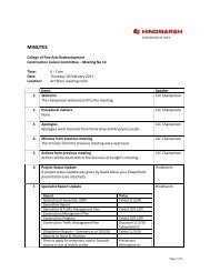
8/08/2013 Page 18 of 47Typical Connection for Gate Meters and Sub-Meters240vsupplyION6200Electricity MeterModbus Protocol(RS485 double pair)ETGRequired OutputsPhase and Line Voltage (VL-N, VL-L)Current Total and per phase (A)Frequency (HZ)Power total and per phase (W, VA and VAr)Power Factor (lead/lag)<strong>Energy</strong> (kWh)Demand (max kVA)Export/Import (kWh if required)240vsupplyPLCModbuscompatibleElster WaterMeter(Pulse Output)(2C/4C Twisted cable)AMPY GasDiaphragm Meter(Pulse Output)(2C/4C Twisted cable)Ethernet Protocol(CAT5 or superior)<strong>UNSW</strong>Port<strong>UNSW</strong>VLAN11Optional Connection EthernetProtocol (CAT5 or superior)SectionENERGY MANAGEMENT UNITGeneral Notes- ETG stands for Ethernet Getaway. ETG modelTSXETG100 preferred.- PLC stands for Programmable Logic Controller.TWIDO Compact PLC preferred.- Electricity Meter ION6200 to have Part Number“ION6200-A0A0B0A0B0R”- <strong>UNSW</strong> ports to be patched to VLAN 11, FM<strong>Energy</strong> <strong>Management</strong> to assign IP address.- Meter Types, PLC, ETG and connectionarrangements to be approved by FM <strong>Energy</strong><strong>Management</strong> before installation.- In case that electricity meters are connected togeneration plants (Cogen, Trigen, PV, etc.) andbuilding loads, the export and import registersshould be correctly configured.- Some electricity meters and PLCs, can beconnected directly to <strong>UNSW</strong> LAN using ethernetcable. In this case the ETG is not required.- If the gas meter and the area in the vicinity of thegas meter are deemed hazardous, then anIntrinsically Safe (IS) barrier should be used.- For more details refer to <strong>UNSW</strong> metering D&Cguidelines “DESIGN AND CONSTRUCTIONREQUIREMENTS INSTALLATION OF GAS,ELECTRICITY AND WATER METERS”.Created ModifiedSep 2012 October 2012DrawnJB/LGDiscipline<strong>Energy</strong>CAD ReferenceApprovedNJScaleTypical Meter Connectionsv2.vsdTitleTypical Gate Meter or Sub-Meter ConnectionSchematicDrawing No:EU-MG-001Sheet No:1 OF 2<strong>Rev</strong>ision2Modbus Protocol(RS485 double pair)
8/08/2013 Page 19 of 47A7.10 ELECTRICITY METER WIRING DIAGRAM(Next Page)
8/08/2013 Page 20 of 47
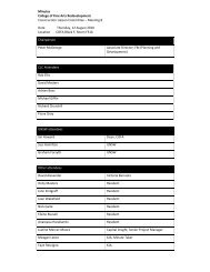
8/08/2013 Page 21 of 47A7.11 ELECTRICITY METER INSTALLATION CHECKLISTE L E C T R I C I T YMeter ChecklistMeter IDPlease return completed sheet to <strong>UNSW</strong> <strong>Energy</strong> Manager – Mathews Building Lv3 (Ph: 9385-3401)ElectricityMeter:Location:InstallingCompany:Date:The following is a checklist to cover the majority of what needs to be considered or taken intoaccount when installing a Digital Power Meter (DPM) and connecting it to the <strong>Energy</strong> <strong>Management</strong>System (EMACS). It is not intended to be all encompassing as every scenario will be different.Put an X in the check box when the checklist item has been addressed and add a comment whererequired.Checklist Item Pass N/A CommentHave the hazards and potential risks of the installationbeen identified (SWMS)? Does this meter satisfy one of the criteria of being eithera major supply to the Campus, a building total or asignificant building load?Has the Meter Data Form been filled in and approvalgiven to proceed by the <strong>UNSW</strong> <strong>Energy</strong> Manager?NB This is the most important step as without thisapproval the meter will not be connected to EMACS. Itwill also give direction on what type of meter to be used.Does a shutdown or outage need to be organised toinstall the meter? Have the CT’s been sized according to the load andrequired burden? Has the best location for the CT’s, potential fuses, linksand terminals been determined? Can the meter be installed on the MSB/DB/MSSB ordoes it require a new panel or can it be mounted in anexisting meter panel?Where is the best location for CT shorting links?NB Shorting links maybe required in both the MSB andmetering panel to ensure the CTs are never left opencircuited under load, especially if cabling or a metercannot be installed straight away.
8/08/2013 Page 22 of 47Has the method of connection to the network beendetermined? Can it be connected to any existing RS485chain or is a new ETG required?If a new ETG is required contact the <strong>Energy</strong><strong>Management</strong> Team to determine the best location. Doesa new data port need to be installed?Is the installation phase complete, i.e. meter, CTs,potentials, terminals, CT shorting links, comms, wirenumbers, etc?Has the meter been configured, i.e. with CT ratios,Modbus address and the energy value reset? Commissioning – has the commissioning ValidationCheck Sheet been completed and EMACS can read themeter?Has an ID number been returned by the <strong>Energy</strong><strong>Management</strong> Representative to enable labels to bemade?Have all of the required labels been installed? Documentation - has the Meter Data Form beencompleted and handed over to the <strong>Energy</strong> Manager/<strong>Energy</strong> <strong>Management</strong> Representative?Documentation - have the <strong>Metering</strong> Schematics beenupdated to reflect the new meter as per the procedure? Documentation - have photos of the completedinstallation been taken and forwarded onto the <strong>Energy</strong><strong>Management</strong> Representative?Documentation – has this checklist and attachedprocedures been completed, signed off and forwardedonto <strong>Energy</strong> Manager/ <strong>Energy</strong> <strong>Management</strong>Representative?SignedObserverCompanyDate
8/08/2013 Page 23 of 47A7.12 WATER METER INSTALLATION CHECKLISTW A T E RMeter ChecklistMeter IDPlease return completed sheet to <strong>UNSW</strong> <strong>Energy</strong> Manager – Mathews Building Lv3 (Ph: 9385-3401)WaterMeter:Location:InstallingCompany:Date:The following is a checklist to cover the majority of what needs to be considered or taken intoaccount when installing a water meter and connecting it to the <strong>Energy</strong> <strong>Management</strong> System(EMACS). It is not intended to be all encompassing as every scenario will be different.Put an X in the check box when the checklist item has been addressed and add a comment whererequired.Checklist Item Pass N/A CommentHave the hazards and potential risks of the installationbeen identified (SWMS)? Has the Meter Data Form been filled in and approvalgiven to proceed by the <strong>UNSW</strong> <strong>Energy</strong> Manager?NB This is the most important step as without thisapproval the meter will not be connected to EMACS. Itwill also give direction on what type of meter to be used.Does a shutdown or outage need to be organised toinstall the meter? Have the CT’s been sized according to the load andrequired burden? Has the best location for the CT’s, potential fuses, linksand terminals been determined? Can the meter be installed on the MSB/DB/MSSB ordoes it require a new panel or can it be mounted in anexisting meter panel?Where is the best location for CT shorting links?NB Shorting links maybe required in both the MSB andmetering panel to ensure the CTs are never left opencircuited under load, especially if cabling or a metercannot be installed straight away.Has the method of connection to the network beendetermined? Can it be connected to any existing RS485chain or is a new ETG required?
8/08/2013 Page 24 of 47If a new ETG is required contact the <strong>Energy</strong><strong>Management</strong> Team to determine the best location. Doesa new data port need to be installed?Is the installation phase complete, i.e. meter, CTs,potentials, terminals, CT shorting links, comms, wirenumbers, etc?Has the meter been configured, i.e. with CT ratios,Modbus address and the energy value reset? Commissioning – has the commissioning ValidationCheck Sheet been completed and EMACS can read themeter?Has an ID number been returned by <strong>Energy</strong><strong>Management</strong> Representative to enable labels to bemade?Have all of the required labels been installed? Documentation - has the Meter Data Form beencompleted and handed over to the <strong>Energy</strong> Manager/<strong>Energy</strong> <strong>Management</strong> Representative?Documentation - have the <strong>Metering</strong> Schematics beenupdated to reflect the new meter as per the procedurebelow?Documentation - have photos of the completedinstallation been taken and forwarded onto <strong>Energy</strong><strong>Management</strong> Representative?Documentation – has this checklist and attachedprocedures been completed, signed off and forwardedonto <strong>Energy</strong> Manager/ <strong>Energy</strong> <strong>Management</strong>Representative?SignedObserverCompanyDate
8/08/2013 Page 26 of 47If a new ETG is required contact the <strong>Energy</strong><strong>Management</strong> Team to determine the best location. Doesa new data port need to be installed?Is the installation phase complete, i.e. meter, CTs,potentials, terminals, CT shorting links, comms, wirenumbers, etc?Has the meter been configured, i.e. with CT ratios,Modbus address and the energy value reset? Commissioning – has the commissioning ValidationCheck Sheet been completed and EMACS can read themeter?Has an ID number been returned by <strong>Energy</strong><strong>Management</strong> Representative to enable labels to bemade?Have all of the required labels been installed? Documentation - has the Meter Data Form beencompleted and handed over to the <strong>Energy</strong> Manager/<strong>Energy</strong> <strong>Management</strong> Representative?Documentation - have the <strong>Metering</strong> Schematics beenupdated to reflect the new meter as per the procedurebelow?Documentation - have photos of the completedinstallation been taken and forwarded onto <strong>Energy</strong><strong>Management</strong> Representative?Documentation – has this checklist and attachedprocedures been completed, signed off and forwardedonto <strong>Energy</strong> Manager/ <strong>Energy</strong> <strong>Management</strong>Representative?SignedCompanyObserverDateI:\EDFO\FM\Asset <strong>Management</strong>\<strong>Energy</strong> <strong>Management</strong>\METER RELATED\<strong>Metering</strong> Design Guide\June 2013 Update\<strong>UNSW</strong>ENERGY MANAGEMENT METERING REV4.2 08082013.docx
8/08/2013 Page 28 of 47VALIDATION OF METER SUPPLYWhere possible and safe to do so, a portable digital analyser shall be used to validate the configurationof the meter by comparing it’s readings with the meter display values.VALIDATION OF METER POTENTIAL SUPPLY415 V/240V/110VMETER AUXILIARY SUPPLY FUSE (2Amp) YES / NO AmpCORRECT POTENTIAL SUPPLY VALUES YES / NO By TestCORRECT CURRENT VALUES YES / NO By TestCORRECT POTENTIAL SUPPLY PHASING YES / NO Wire Colour/remove fusesCORRECT CURRENT PHASING YES / NO Wire Colour/shorting CTsComments………………………………………………………………………………….COMMUNICATIONS VALIDATIONFor multiple meters within the same communications chain, only reading the meter from the ETG isrequired for every meter within that chain. The other checks refer to the whole communications chain.VISUAL CHECK OF SERIAL COMMSETG CONNECTED TO VLAN 11ETG CONFIGUREDMETER READ FROM ETGYES / NOYES / NOYES / NOYES / NOEMACS VALIDATIONThere is the need for enough variability between the different meters to ensure that what is displayedat EMACS matches its corresponding Panel Meter.PHASE A PHASE B PHASE C AVERAGE/TOTALVOLTAGE YES / NO YES / NO YES / NO YES / NOCURRENT YES / NO YES / NO YES / NO YES / NOPOWER YES / NO YES / NO YES / NO YES / NOREADING DATE TIME METERREADING12Consumption (difference)EMACSREADINGWORK REQUIRED TO COMPLETE VALIDATION..………..……………………………………………………………………………………………………………………………………………………………………………………FAULTS / REPAIRS ON METERING / SWITCHBOARD..……….…………………………………………………………………………………………………………………………………………………………………………………...SignedCompanyObserverDateI:\EDFO\FM\Asset <strong>Management</strong>\<strong>Energy</strong> <strong>Management</strong>\METER RELATED\<strong>Metering</strong> Design Guide\June 2013 Update\<strong>UNSW</strong>ENERGY MANAGEMENT METERING REV4.2 08082013.docx
8/08/2013 Page 31 of 47A7.16 METER DATA FORMSThis includes:• Electricity Meter Data Form• Water Meter Data Form• Gas Meter Data Form(Following Pages)I:\EDFO\FM\Asset <strong>Management</strong>\<strong>Energy</strong> <strong>Management</strong>\METER RELATED\<strong>Metering</strong> Design Guide\June 2013 Update\<strong>UNSW</strong>ENERGY MANAGEMENT METERING REV4.2 08082013.docx
8/08/2013 Page 32 of 47E L E C T R I C I T YMeter Data FormOffice Use OnlyMeter IDPlease return completed form to <strong>UNSW</strong> <strong>Energy</strong> Manager – Mathews Building Lv3 (Ph: 9385-3401)SECTION A. Pre-Installation Meter DetailsNew Meter (Y/N) Load Change (Y/N) Replacement (Y/N) Disconnect (Y/N)ManufacturerModelBuilding Name Grid Ref. RoomMeter LocationDescription(Please be specific)Load DescriptionWhat’s connected tothe meter? (details)Floor LocationIs meter external to building? Y/NSECTION B. Communications DetailsMeter Serial/Ethernet? Modbus AddressGateway/Meter ID No. Port No. IP AddressCommentsSECTION C. Post Installation Meter DetailsCT Ratio Serial No. Meter ReadingCommentsSECTION D. Installer DetailsName of Installer Contact No. Date / /Name of Reporter Contact No. Date / /Office Use Approved? Y/N Date / /SpecialCondition(s)SignatureTITLE: <strong>UNSW</strong> ENERGY MANAGEREMS Recorder Contact No. Date / /SECTION E. Completion<strong>Energy</strong> <strong>Management</strong> : Has A Copy Of This Form Been Returned To Installer (Y/N)Installer : When Meter Has Been Installed - Email energy@unsw.edu.au (Y/N)I:\EDFO\FM\Asset <strong>Management</strong>\<strong>Energy</strong> <strong>Management</strong>\METER RELATED\<strong>Metering</strong> Design Guide\June 2013 Update\<strong>UNSW</strong>ENERGY MANAGEMENT METERING REV4.2 08082013.docx
8/08/2013 Page 35 of 47A7.17 PLC / ETG DATA FORM(Following Page)I:\EDFO\FM\Asset <strong>Management</strong>\<strong>Energy</strong> <strong>Management</strong>\METER RELATED\<strong>Metering</strong> Design Guide\June 2013 Update\<strong>UNSW</strong>ENERGY MANAGEMENT METERING REV4.2 08082013.docx
8/08/2013 Page 38 of 47I:\EDFO\FM\Asset <strong>Management</strong>\<strong>Energy</strong> <strong>Management</strong>\METER RELATED\<strong>Metering</strong> Design Guide\June 2013 Update\<strong>UNSW</strong> ENERGY MANAGEMENT METERING REV4.208082013.docx
8/08/2013 Page 39 of 47A7.19 EXAMPLE OF GAS METERING SCHEMATIC(Following Page)I:\EDFO\FM\Asset <strong>Management</strong>\<strong>Energy</strong> <strong>Management</strong>\METER RELATED\<strong>Metering</strong> Design Guide\June 2013 Update\<strong>UNSW</strong>ENERGY MANAGEMENT METERING REV4.2 08082013.docx
8/08/2013 Page 40 of 47I:\EDFO\FM\Asset <strong>Management</strong>\<strong>Energy</strong> <strong>Management</strong>\METER RELATED\<strong>Metering</strong> Design Guide\June 2013 Update\<strong>UNSW</strong> ENERGY MANAGEMENT METERING REV4.208082013.docx
8/08/2013 Page 41 of 47A7.20 EXAMPLE OF WATER METERING SCHEMATIC(Following Page)I:\EDFO\FM\Asset <strong>Management</strong>\<strong>Energy</strong> <strong>Management</strong>\METER RELATED\<strong>Metering</strong> Design Guide\June 2013 Update\<strong>UNSW</strong>ENERGY MANAGEMENT METERING REV4.2 08082013.docx
8/08/2013 Page 42 of 47I:\EDFO\FM\Asset <strong>Management</strong>\<strong>Energy</strong> <strong>Management</strong>\METER RELATED\<strong>Metering</strong> Design Guide\June 2013 Update\<strong>UNSW</strong> ENERGY MANAGEMENT METERING REV4.208082013.docx
8/08/2013 Page 43 of 47A7.21 EXAMPLE OF COMMUNICATIONS NETWORK SCHEMATIC(Following Page)I:\EDFO\FM\Asset <strong>Management</strong>\<strong>Energy</strong> <strong>Management</strong>\METER RELATED\<strong>Metering</strong> Design Guide\June 2013 Update\<strong>UNSW</strong>ENERGY MANAGEMENT METERING REV4.2 08082013.docx
8/08/2013 Page 44 of 47I:\EDFO\FM\Asset <strong>Management</strong>\<strong>Energy</strong> <strong>Management</strong>\METER RELATED\<strong>Metering</strong> Design Guide\June 2013 Update\<strong>UNSW</strong> ENERGY MANAGEMENT METERING REV4.208082013.docx
8/08/2013 Page 45 of 47A7.22 PREFERRED EQUIPMENT LISTSECTION DESCRIPTION MANUFACTURER MODELElectricity Electricity meter - ION7650 Schneider M7650A0C0B5E0A0EElectricity meter – PM850 Schneider PM850MGElectricity meter – PM750 Schneider PM750MGElectricity meter – PM5350 Schneider PM5350Electricity meter – ION6200 Schneider ION6200-A0A0B0A0B0RElectricity meter – IEM3250 Schneider iEM3250/3255Water Water Meter with pulse head Elster V100 (PMS-T)Water Meter with pulse head Elster H4000Gas Gas Meter with pulse attachment Ampy Email AL 425Gas Meter with pulse attachment Ampy Email AL 800Gas Meter with pulse attachment Ampy Email AL 1000Gas Meter with pulse attachment Ampy Email AL1400Comms Ethernet to Serial ETG Schneider -TSXETG100ConneXiumPLC Twido PLC for pulse collecting Schneider - Twido TWDLCAA24DRFTwido RS485 Comms Adapter Schneider - Twido TWDNAC485TTwido Ethernet Adapter Module Schneider - Twido 499TWD01100Twido Analogue Input Module Schneider - Twido TWDAMI8HTRS485 2 tw pr shielded grey cable Belden 9842I:\EDFO\FM\Asset <strong>Management</strong>\<strong>Energy</strong> <strong>Management</strong>\METER RELATED\<strong>Metering</strong> Design Guide\June 2013 Update\<strong>UNSW</strong> ENERGY MANAGEMENT METERING REV4.208082013.docx
8/08/2013 Page 46 of 47A7.23 TYPICAL INTRINSIC SAFE BARRIER RELAY BOX ARRANGEMENT(Next Page)I:\EDFO\FM\Asset <strong>Management</strong>\<strong>Energy</strong> <strong>Management</strong>\METER RELATED\<strong>Metering</strong> Design Guide\June 2013 Update\<strong>UNSW</strong>ENERGY MANAGEMENT METERING REV4.2 08082013.docx
8/08/2013 Page 47 of 47I:\EDFO\FM\Asset <strong>Management</strong>\<strong>Energy</strong> <strong>Management</strong>\METER RELATED\<strong>Metering</strong> Design Guide\June 2013 Update\<strong>UNSW</strong>ENERGY MANAGEMENT METERING REV4.2 08082013.docx
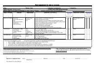
A7.24 APPLICABLE AUSTRALIAN METERING STANDARDSElectricity meter standards:• AS 1284:1-2004: Electricity metering - General purpose induction watthour meters,• AS 62052.11-2005: Electricity metering equipment (AC) – General requirements,tests, test conditions – <strong>Metering</strong> equipment,• AS 62053.21-2005: Electricity metering equipment (AC) – Particular requirements –Static meters for active energy (classes 1 and 2), and• AS 62053.22-2005: Electricity metering equipment (AC) – Particular requirements –Static meters for active energy (classes 0.2S and 0.5S)Voltage transformer standards:• AS 60044.2-2007: Instrument transformers Inductive voltage transformers,• AS 60044.3-2004: Instrument transformers - Combined transformers,• AS 60044.5-2004 (part): Instrument transformers - Capacitor voltage transformersand• AS 1243-1982: Voltage Transformers for Measurement and Protection (for 3 phaseonly)Current transformers standards:• AS 60044.1-2007: Instrument transformers - Current transformers and• AS 60044.3-2004: Instrument transformers - Combined transformers.