218100 - Frederiksen
218100 - Frederiksen
218100 - Frederiksen

You also want an ePaper? Increase the reach of your titles
YUMPU automatically turns print PDFs into web optimized ePapers that Google loves.
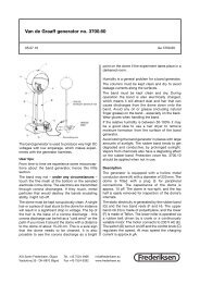
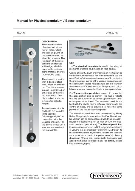
Manual for Physical pendulum / Bessel pendulum18.04.13 2181.00 AEDescriptionThe device consistsof a steel rod with arow of holes, whichare used as pivots ofthe pendulum and forattaching weights. Thefixed part of the pivotconsists of a robustknife edge, which isfastened to ordinarystand material or preferablya table edge.The device is suppliedwith 4 discs of steeland 2 discs of aluminium.The discs are usedin pairs - positioned oneither side of the steelrod with a bolt. Twodiscs, a bolt and a nutis hereafter called aweight.Two extra sets of nutsand bolts are includedto be used as”trimming weights” inconnection with theBessel pendulum. Forthe Bessel pendulum 4washers are used withthe big weights.Use1 – The physical pendulum is used in the study ofmoments of inertia and motion of rigid bodies.Centre of gravity, pivot and moment of inertia can bevaried in countless ways. For the calculations you willneed Steiner’s theorem and a number of formulae forthe moments of inertia of the various components ofthe pendulum. These relationships can be found inthe Moments of Inertia section. The practical calculationsare most conveniently done in a spreadsheet.2 – The reversion pendulum is used to determinethe acceleration due to gravity. The name reflectsthat the pendulum can be turned upside down - thereis a pivot at each end. The reversion pendulum isbuilt with the pivots having different distances to thecentre of mass, and is adjusted to have the sameperiod for the two suspension points.The reversion pendulum was developed by HenryKater. The principle was refined by F.W. Bessel, andhis version can be demonstrated with this device (althoughthe accuracy is not as high as with the classicalprecision pendulums). The Bessel pendulumis a reversion pendulum, which is symmetric in termsof volume (i.e. geometrically symmetric), although itsmass distribution is asymmetric. It turns out that twosources of error due to the presence of air therebydisappear. (These are, respectively, buoyancy andadded inertia due to dragged air.) For details, pleasesee the bibliography.A/S Søren <strong>Frederiksen</strong>, Ølgod Tel. +45 7524 4966 info@frederiksen.euViaduktvej 35 · DK-6870 Ølgod Fax +45 7524 6282 www.frederiksen.eu®
A bit of theoryWe will consider a rigid body as composed of a largenumber of small components.The moment of inertia of the body about a givenaxis is then given as a sum of contributions from theindividual components, each of the formThe large discs have the form of a cylinder with a cylindricalhole in the centre. The weights are attachedby a bolt which we can consider as a point mass.(Meaning that we ignore the bolt’s moment of inertiaabout its own centre – but not its mass.)Below are some formulae for moments of inertia.Rectangle with dimensions b x d and mass m:where m jis the mass of component no. j and r jis thedistance between this and the axis of rotation.The total moment of inertia can thus be written inthe formIn practice, moments of inertia are determined byintegration. If the body shape is sufficiently simple,this can be done analytically. There are a number ofrelevant examples of this in a later section.If the moment of inertia about an axis through thebody’s centre of gravity is called I G, the moment ofinertia I about any other axis which is parallel to thefirst can be determined by using Steiner’s theorem:Semicircle of radius r and mass m, translated by D:Here, M is the mass of the body and a is the distancebetween the two axes.This theorem is extremely useful for calculating themoments of inertia, except for the simplest cases.The term ”physical pendulum” is used when a rigidbody is suspended from an axis which does not passthrough the centre of gravity.The period of the physical pendulum is given byCylinder with outer radius r 2, inner radius r 1and massm:where I is the moment of inertia about the axis ofrotation, and M is the mass, a is the distancebetween the pivot and the centre of mass, g is theacceleration due to gravity.Moments of inertiaIt follows from the definition of moment of inertia thatfor a rigid body, the total moment of inertia about anaxis can be found as a sum of the moments of inertiaof the individual parts about this axis.In this case, we will divide the pendulum rod into arectangular piece and two semicircular ends. (Thematerial from the 11 square holes should be subtractedfrom this, if you want to be exact.)The work with keeping track of all the separate partsof the pendulum is best done in a spreadsheet.The mass of the rod is distributed among the threeparts proportional to their areas.®
Measuring the periodWith a stopwatchYou measure the time for a number of completeoscillations and divide by the number. The accuracyis increased if you start and stop the watch when thependulum passes its lowest point where its speed ishighest. Fix your sight on something vertical behindthe pendulum, and do not move your head betweenstart and stop.In practice, you can hardly achieve lower uncertaintythan 0.2 s.For an accuracy of e.g. 0.5%, the total measurementtime must be at least 40 s.With the Bessel pendulum you should not aim forless accuracy than 0.1%, corresponding to 200seconds of measurement time.Using data loggingPlace a motion sensor about 20 cm from the pendulumpointing at one of the weights. (It takes luckto measure the motion of the rod alone – but it canbe done.) Set the data acquisition program to measureposition with a sampling frequency of e.g. 100Hz. Ensure that the data collected roughly shows asinusoidal curve - there must not be odd spikes indicatingthat the sensor misses the target.Continue measuring for “sufficiently long time”. Withthe Bessel pendulum, approx. one minute is needed.If the precision requirements are less strict, the timecan be reduced.Fit the data points with a damped sinus oscillation.Be sure to set the program to display sufficient numberof digits of the parameters!With a photogate and a counterSuspend the pendulum vertically, completely at rest.Place the photogate so the light is just ”touching” avertical edge near the bottom of the pendulum (theedge of the rod or eventually the edge of a weight).Photocell type 1975.50 has a green LED that turnsoff when light beam is interrupted.When the pendulum swings (small oscillations!) thelight beam is to be blocked throughout one half oscillationperiod and to pass during the other. Thus theperiod is the time from the start of one interruptionto the next one.With counter 2002.50, the procedure is the following:1. Connect the photocell to DIN connector A2. Pull the pendulum a little away from thephotogate during the following steps3. Press Select repeatedly until Period is lit4. Wait until the lamp Continuous is lit, thenpress Memory/Continuous5. Finally press Start/Stop6. Now the pendulum can be releasedSome programs deliver the oscillation time T directly,others use ω = 2π/T.The results are shown as an average of two periods.Read out many values and use the average.®
Physical pendulum – experiment procedureWhen working with the general physical pendulum,neither washers nor the extra set of bolts are needed.There are enough variations even so!Experiments 1, 2 and 3 below may be carried outindependently of each other.Fix the metal discs with the bolts - it is enough totighten them with your fingers.The knife edge pivot can for simple demonstrationexperiments be used with a retort stand rod and anA foot or a table clamp. More accurate results areachieved by clamping the knife edge pivot to theedge of a steady table with a cramp. Preferably justabove a table leg. If possible, use a table that is securedto a wall.Note: There is a position difference when a hole isused for a pivot (upper edge) or as the location fora weight (centre). Be careful to use the right values.The amplitude of the oscillations should be small.About a centimetre is fine.Calculations – Moment of inertia of the rodThe formula for the period can be rewritten asfollowsSince the centre of gravity is located in the centre ofthe rod, everything on the left-hand side is known.The total mass M is equal to the mass m Rof the rod.For the rod without weights the right-hand side canbe rewritten using Steiner’s theorem:It follows that if the values of are plotted asa function of a 2 , the results should lie on a straightline with the rod mass m Ras slope and moment ofinertia of the rod about its centre I Ras the intersectionwith the y-axis.1 – Moment of inertia of the rodMeasure the period as an average over at least 20cycles for each of the 6 possible pivots (centre holeincluded).Measure the distance from the centre of the rod toeach of the five pivots precisely. The centre is markedwith a thin line – it may be an idea to temporarilyextend the line across the centre hole using the edgeof a strip of adhesive tape. (These distances are alsoused in the following experiments.)For comparison, calculate the moment of inertia ofthe rod about its centre by dividing it into two semicircularends and a rectangular piece in the centre– see also ”Inertia Moments”. Ignoring the squareholes only results in a relatively small error.To determine the mass of the three parts, distributethe total mass of the rod proportional to the areas ofthe three parts.2 – Symmetrical mass distributionSelect a position of the weights – e.g. the next outermosthole. The locations must be symmetrical, sothe pendulum still has the centre of mass in the centreof the rod.In order to avoid that the pendulum ”capsizes”,when using the centre hole as pivot, the bolts can bepointing in opposite directions.Measure the period as an average over at least 20cycles for each of the 5 possible pivots (centre holeincluded).If you have not already determined these: Measurethe distance from the centre of the rod to each of thefive pivots precisely. The centre is marked with a thinline – it may be an idea to temporarily extend the lineacross the centre hole using the edge of a strip ofadhesive tape. (These distances are also used in thefollowing experiment.)Repeat eventually the measurement series with theweights in a new – but still symmetrical – position.®
Calculations – Symmetrical mass distributionThe formula for the period can be rewritten as followsFor symmetry reasons, the centre of gravity islocated in the centre of the rod, so everything on theleft-hand side is known. The right-hand side can berewritten using Steiner’s theorem:It follows that if the values are plotted as afunction of a 2 , the results should lie on a straight linewith pendulum mass M as slope and the moment ofinertia of the pendulum about its centre of mass I Gasthe intersection with the y-axis.We can compare the value found for I Gwith one calculatedaswhere I Ris the moment of inertia of the rod about itscentre, I Wis the moment of inertia of the weight aboutits centre axis, m Wis the mass of the weight and x Wis the distance between centres of the rod and theweight.I Rand I Ware calculated using the formulae in thesection ”Moments of inertia”. The weights are consideredas two cylinders, to be treated as extendedbodies, plus a bolt and a nut, which to a good approximationcan be considered as point-shaped.If more than one series of measurements are performed,the graphs will be parallel.3 - arbitrary mass distributionWe are now dealing with the situation where thereis no longer symmetry about the centre of the rod.Thus, we must not only determine the moment ofinertia of the pendulum, but also the centre of mass.Measure the distance from the centre of the rod toeach of the possible pivots accurately. The centre ismarked with a thin line – it may be an idea to temporarilyextend the line across the centre hole using theedge of a strip of tape.In order to specify positions unequivocally, we definea coordinate axis along the rod, with zero in the rodcentre and the positive direction upward. Positionsbelow centre of the rod are negative.Call the pivot position x P. The positions of theweights are designated x A, resp. x B, and their massesm A, resp. m B.Note the experimental conditions carefully and measurethe period averaged over at least 20 times.Calculations - arbitrary mass distributionSince the centre of mass of the rod has the coordinate0, we get the centre of mass position x GThe distance from the axis of rotation to the centreof mass is given byThe pendulum’s moment of inertia about the pivotis calculated by summing the contributions from therod and the two weights:where I Aand I Bdenotes the moment of inertia ofweight A and B about the weight’s own centre.Now, a theoretical value for the oscillation time canbe calculated and compared with the experimentalone.®
Bessel pendulum –experiment procedureThe mass of the weights must be increased slightly:Mount two steel discs with a bolt and two washersin the outermost hole in the rod at one end, and thetwo aluminium discs at the opposite end – also withwashers.The pendulum is suspended in the last but one holeat each end – i.e. the outermost free hole. The knifepivot is clamped to a table edge – normal stand materialis not stable enough.The pivot in the end with the steel weight is calledP 1, the pivot near the aluminium weight is calledP 2. The two corresponding periods are called T 1andT 2.It is necessary to measure the oscillation periodvery accurately. With a stopwatch at least 150 periodsmust be measured. Proper use of photogatesor data acquisition equipment is better than using astopwatch.As before, the amplitude must be small.The trimming weights, comprising a bolt with a nut,should always be located symmetrically around thecentre of the rod. For a start, place them in the twoholes 50 mm from the centre.Use the pivot P 1and determine T 1. Reverse the pendulumusing P 2and determine T 2.Move the trimming weights symmetrically to the nexthole and repeat. Ditto for the last vacant hole.The period varies when the trimming weights aremoved. When they are as close to each other aspossible, T 1will be less than T 2. Conversely, whenthe trimming weights are as far apart as possible, theperiod T 2is less than T 1. For some distance, the twoperiods must be equal. We are looking for the exactvalue of this common period T:Use a spreadsheet to graph T 1and T 2as a functionof the distance x Tfrom the centre to the trimmingweights. Add parabolas (quadratic function, polynomialof degree 2) as ”trend lines”. Add sufficienthorizontal subdivisions to the y axis, and read thecommon period where the graphs are crossing.The last measurement needed is the distance Δxbetween P 1and P 2. The measure is taken from theupper rim of the upper hole to the lower rim of thelower hole.Now the local acceleration due to gravity can befound:The period of oscillation must be determined so accuratelythat the overall accuracy is determined bythe measurement of Δx. On the classical precisionpendulums this distance could for instance be foundby interferometry.®
The acceleration due to gravity – comparisonThe experimentally determined value of g can becompared with the theoretical value for the smoothearth ellipsoid, compensated for height:Here, ϕ is the latitude. The height correction is splitinto two parts C FAand C B. (Free Air correction andBouguer correction). They represent, resp. a reductionof g due to larger distance to the earth’s centreand an increase in g due to the increased gravityfrom the extra layers of soil:Reversion pendulum – theoryThe pendulum has mass M and the moment of inertiaabout the centre of mass G is called I G.The moment of inertia about P 1resp. P 2is called I 1resp. I 2.The distance between G and P 1is called x 1and thedistance between G and P 2called x 2.According to Steiner’s theorem we now have thatThe two periods are given byIf T 1= T 2, this means thatHere, h is the height above sea level.In C Bwe need the average density ρ of the soil layersbetween sea level and the position. Using a typicaldensity of 2670 kg/m 3 , these two corrections to bejoined:Assuming that x 1≠ x 2, this equation can be solvedin terms of I GFrom this we obtain the period asIn practice, the easiest way to find the latitude is byusing a service like Google Maps. The height abovesea level can possibly be found via the municipalwebsite – search for a section with geographicaldata (”GIS”). Or use a good map.Where Δx denotes the distance between the pivots.®
Teacher NotesScience conceptsCenter of mass - assumed known.Moment of inertia, Steiner’s theorem and period forphysical pendulum - formulae are summarized.Reversion pendulum - the formula for the oscillationperiod is derived.Mathematical prerequisitesEquation Solving, trigonometric functions, use ofspreadsheets, graphs.Derivation of the formulae for moments of inertia requiresintegral calculus.Didactic considerationsCalculation of the moment of inertia of the rod canbe simplified by ignoring the holes. This causes anerror in the rod moment of inertia about the centre ofjust over 1%.Calculated oscillation periods of the rod alone willincrease by up to 0.5%. (The greatest deviation forpivot in the centre hole.) With weights mounted onthe rod, period deviations will be less.An even more obvious simplification can be done byconsidering bolts, nuts and washers as point masses.The error in calculations of moment of inertia willbe less than 0.08%, the period error is half of that.These errors will probably be negligible comparedto measurement uncertainties and other sources oferror when working with the general physical pendulum.Note that these errors are irrelevant when the deviceis used as a reversion pendulum !!!It seems tempting to expand the calculations of experiment2 – Symmetrical mass distribution by findingthe moment of inertia of the weight about itsown centre. This requires subtraction of two nearlyequal values, and will therefore be subject to veryhigh uncertainty. It is only recommended if you wantto dig into uncertainty calculations – otherwise, thediscrepancy between theory and measurement willonly create frustration.The best procedure is to repeat experiment 2 for allthe possible values of x L, then I Gcan be plotted asa function of x L2. The interception with the y-axis isthen I R+ 2 I W.On www.frederiksen.eu you will find a completespreadsheet for calculating moments of inertia etc...Search for part number 2181.00LiteratureD. Candela, K. M. Martini, R. V. Krotkov, and K. H.Langley:Bessel’s improved Kater pendulum in the teachinglabAmerican Journal of Physics - June 2001 - Volume69, Issue 6, pp. 714Equipment listThe following is suggested:2181.00 Physical pendulum / Bessel pendulum0015.10 Clamp2002.50 Electronic Counter1975.50 Fotocell unit0016.00 Table clamp0023.10 Universal bosshead (2 are used)0008.50 Retort Stand Rod 25 cm0008.20 Retort Stand Rod 75 cmA/S Søren <strong>Frederiksen</strong>, Ølgod Tel. +45 7524 4966 info@frederiksen.euViaduktvej 35 · DK-6870 Ølgod Fax +45 7524 6282 www.frederiksen.eu®