Design and Analysis of Rocket Motor Casing by Using Fem Technique
Design and Analysis of Rocket Motor Casing by Using Fem Technique
Design and Analysis of Rocket Motor Casing by Using Fem Technique
Create successful ePaper yourself
Turn your PDF publications into a flip-book with our unique Google optimized e-Paper software.
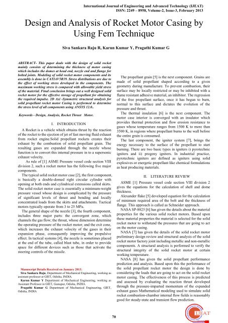
International Journal <strong>of</strong> Engineering <strong>and</strong> Advanced Technology (IJEAT)ISSN: 2249 – 8958, Volume-2, Issue-3, February 2013<strong>Design</strong> <strong>and</strong> <strong>Analysis</strong> <strong>of</strong> <strong>Rocket</strong> <strong>Motor</strong> <strong>Casing</strong> <strong>by</strong><strong>Using</strong> <strong>Fem</strong> <strong>Technique</strong>Siva Sankara Raju R, Karun Kumar Y, Pragathi Kumar GABSTRACT- This paper deals with the design <strong>of</strong> solid rocketmainly consists <strong>of</strong> determining the thickness <strong>of</strong> motor casingwhich includes the domes at head end, nozzle end <strong>and</strong> flange forbolted joints. Modeling <strong>of</strong> solid rocket motor components <strong>and</strong> itsassembly is done in CATIAV5R19. Stress distributions are due tothe effect <strong>of</strong> working stress developed in the components. Themaximum working stress is compared with allowable yield stress<strong>of</strong> the material. Final conclusion brings out a well designed solidrocket motor for the effective storage <strong>of</strong> propellant for obtainingthe required impulse. 2D Axi -Symmetric structural analysis forsolid propellant rocket motor <strong>Casing</strong> is performed to determinethe stress level <strong>of</strong> all components using ANSYS 12.0..Keywords - <strong>Design</strong>, <strong>Analysis</strong>, <strong>Rocket</strong> Thrust <strong>Motor</strong>.I. INTRODUCTIONA <strong>Rocket</strong> is a vehicle which obtains thrust <strong>by</strong> the reaction<strong>of</strong> the rocket to the ejection <strong>of</strong> jet <strong>of</strong> fast moving fluid exhaustfrom rocket engine.Solid propellant rockets creates theirexhaust <strong>by</strong> the combustion <strong>of</strong> solid propellant grain. Theresulting gases are exp<strong>and</strong>ed through the nozzle whosefunction is to convert this internal pressure in to a supersonicexhaust velocity.As rule <strong>of</strong> [1] ASME Pressure vessel code section VIIIdivision 2, such a rocket motor has the following five majorcomponents.The typical solid rocket motor case [2], the first component,is basically a double-domed right circular cylinder withopening at both ends <strong>and</strong> cylindrical extensions called skirts.The solid rocket motor case is essentially a minimum-weightpressure vessel whose design is complicated <strong>by</strong> the pressure<strong>of</strong> significant levels <strong>of</strong> thrust <strong>and</strong> bending <strong>and</strong> locallyconcentrated loads from the skirts <strong>and</strong> attachments. Tacticalmotors typically operate from 3 to 25 MPa.The general shape <strong>of</strong> the nozzle [3], the fourth component,includes three major parts: the convergent zone, whichchannels the gas flow; the throat, whose dimension determinethe operating pressure <strong>of</strong> the rocket motor; <strong>and</strong> the exit cone,which increases the exhaust velocity <strong>of</strong> the gases in theirexpansion phase, consequently improving the propulsiveeffect. In tactical systems [4], the nozzle is sometimes placedat the end <strong>of</strong> the tube, called blast tube, in order to providespace for different devices such as those that activate thesteering controls <strong>of</strong> the missile.Manuscript Details Received on January 2013.Siva Sankara Raju, Department <strong>of</strong> Mechanical Engineering, working asassistant pr<strong>of</strong>essor at GIET, Odisha, INDIA.Karun Kumar Y Department <strong>of</strong> Mechanical Engineering, working asAssistant Pr<strong>of</strong>essor in GIET, Gunupur, Odisha, INDIA.Pragathi Kumar G Department <strong>of</strong> Mechanical Engineering, GIET,Odisha, INDIAThe propellant grain [5] is the next component. Grains aremade <strong>of</strong> solid propellant shaped according to a givengeometry during manufacture. To prevent combustion, theirsurface may be locally restricted or may be inhibited with aflame resistant adhesive material, an inhibitor. The regression<strong>of</strong> the free propellant surface, once it has begun to burn,normal to this surface <strong>and</strong> dictates the evolution <strong>of</strong> thepressure <strong>and</strong> thrust.The thermal insulation [6] is the next component. Themotor case interior is converged with an insulator whichprovides thermal protection <strong>and</strong> flow erosion resistance togases whose temperature ranges from 1500 K to more than3500 K, in regions where propellant burns to the wall beforethe entire grain is consumed.The last component, the igniter system [7], brings theenergy necessary to the surface <strong>of</strong> the propellant to startburning. There are two basic types in igniters i) pyrotechnicigniters <strong>and</strong> ii) progeny igniters. In industrial practice,pyrotechnic igniters are defined as igniters using solidexplosives or energetic propellant like chemical formulationsas heat producing materials.II. LITERATURE REVIEWASME [1] Pressure vessel code section VIII division 2gives the equations for the calculation <strong>of</strong> shell <strong>and</strong> domethickness.Alex<strong>and</strong>er flake [5] developed equation for the calculation<strong>of</strong> minimum required area <strong>of</strong> the bolt <strong>and</strong> the thickness <strong>of</strong>flange. This approach is called as Schneider approach.NASA SP-8025 [6] has given the details about the materialproperties for the various solid rocket motors. Based uponthese material properties the material is selected for the solidrocket motor to withst<strong>and</strong> the pressures that are going to acton the motor casing.NASA [7] has given the details <strong>of</strong> the solid rocket motorpreliminary design review <strong>and</strong> structural analysis <strong>of</strong> the solidrocket motor factory joint including metallic <strong>and</strong> non-metalliccomponents. A structural analysis is performed to verify thestructural integrity <strong>of</strong> the solid rocket motor at certainworking temperature.NASA [8] has given the solid propellant performanceprediction <strong>and</strong> analysis. Based upon this the performance <strong>of</strong>the solid propellant rocket motor the design is done <strong>by</strong>considering the loads that are going to act on the solid rocketmotor casing. The effectiveness <strong>of</strong> this process is predicted<strong>and</strong> assessed <strong>by</strong> evaluating the reaction thrust developedthrough the pressure-imparted momentum <strong>of</strong> the exp<strong>and</strong>edexhaust gases Mathematical modeling used to simulate solidrocket combustion-chamber internal flow fields is reasonablygood for steady-state <strong>and</strong> transient flow prediction.70
<strong>Design</strong> And <strong>Analysis</strong> <strong>of</strong> <strong>Rocket</strong> <strong>Motor</strong> <strong>Casing</strong> <strong>by</strong> <strong>Using</strong> <strong>Fem</strong> <strong>Technique</strong>David Heckman [9] in 1988 has explored that the finiteelement analysis is an extremely powdery tool when usedcorrectly. For pressure vessels finite element analysisprovides an additional tool for use in analysis. However, itmust be compared to other available data, not taken as beingcorrect just because it looks right.III. EXPEIMENTA DETAILSI. Requirements for <strong>Rocket</strong> <strong>Motor</strong> <strong>Design</strong>The main required parameters that are considered for thedesign <strong>of</strong> solid rocket motor are Total impulse Duration <strong>of</strong> flight <strong>and</strong> Outer diameter <strong>of</strong> the motorBased on the above required parameters the design <strong>of</strong> solidpropellant rocket motor is classified [17] in two ways givenbelow Internal ballistic design <strong>and</strong> <strong>Rocket</strong> motor hardware designInternal ballistic design mainly consists <strong>of</strong> designing <strong>of</strong>propellant <strong>of</strong> propellant <strong>and</strong> nozzle contour which includesthe exit diameter <strong>of</strong> nozzle <strong>and</strong> throat diameter <strong>of</strong> nozzle.ASME Pressure vessel code section VIII division 2 (1)given the formula for the calculation <strong>of</strong> shell <strong>and</strong> domethickness <strong>and</strong> is given belowThickness <strong>of</strong> the shell is given <strong>by</strong>T = ----- (1)Table 1: Materials used in solid rocket motors (metallic)<strong>and</strong> their propertiesMaterialpropertiesUTS(MPa)0.2%YieldstrengthElongation (%)FracturetoughnessWeldefficiency(%)15CDV6Modified15CDV6Maraging steel(M250)Cobalt-freeMS3Ni-Cr-2Si980 1600 1765 1765 1950835 1470 1725 1725 165010 8 5 5 11100-12090-100 90 90 80-9012.8 21.7 23.1 23.1 25.5IV. PROBLEM DESCRIPTIONThe rocket motor is mainly designed to obtain a particularthrust which mainly depends on exhaust product mass flowrate, exit exhaust velocity, exit exhaust pressure, ambientpressure <strong>and</strong> nozzle exit area. Out <strong>of</strong> which the thrust mainlydepends on the propellant <strong>and</strong> motor characteristics.Propellant[10] <strong>and</strong> motor characteristics may include burningrate, density, burning surface area <strong>and</strong> gas temperature <strong>and</strong>various geometric characteristics <strong>of</strong> the nozzle. The burning<strong>of</strong> propellant gives structural (pressure) <strong>and</strong> thermal loads(temperature). The liner has designed for thermal loadsproduced due to the burning <strong>of</strong> propellant.The paper aims to the design <strong>of</strong> rocket motor casing basedon the volume <strong>of</strong> the propellant it has to store <strong>and</strong> to withst<strong>and</strong>the combustion chamber pressure neglecting the thermalloads produced due to the burning <strong>of</strong> propellant inside thecasing.The design <strong>of</strong> solid rocket motor mainly consists <strong>of</strong>determination <strong>of</strong> the thickness <strong>of</strong> motor casing which includesthe domes at head end, nozzle end <strong>and</strong> flange for the boltedjoins.V. MATERIAL PROPERTIESHigh strength 15CDV6 steel material is chosen [8] NASASP-8025 for motor casing <strong>and</strong> nozzle due to its availability<strong>and</strong> well established fabrication procedure. The specification<strong>of</strong> the material is (table 2) given below.Table 2: material propertiesProperty (Tangential)Along thegrain(Transverse)Across thegrainTensileStrength (MPa) 1080 (min.) 1020 (min.)Yield Strength (MPa) 930 (min.) 850 (min.)%elongation(on50mm)min.10 10Hardness 290-360 290-36060(min.) 60(min.)Impact toughness (J) 2mmcharpy „U‟ notchVI. GENERAL METHODOLOGY FOR THE DESIGNIn the present paper the following steps is followed todesign the solid rocket motor hardware components.Step 1: Determination <strong>of</strong> the thickness <strong>of</strong> the casing shell.Step 2: Determination <strong>of</strong> the thickness <strong>of</strong> the domes at headend <strong>and</strong> nozzle end.Step 3: Determination <strong>of</strong> the thickness <strong>of</strong> the flange for thebolted joints.Step 4: Determination <strong>of</strong> toque required for tightening thebolts.VII. .ROCKET MOTOR SYSTEM DESIGNThe motor casing is designed as per ASME pressure vesselcode. Flange design at head end <strong>and</strong> nozzle end are designedusing Schneider‟s approach. Flange thickness is calculatedusing flat plate closure formula as per ASME pressure vesselcode [1]. Tori-spherical dome configuration is selected <strong>of</strong>easy fabrication for head end <strong>and</strong> nozzle end domes <strong>and</strong>thickness is calculated using ASME pressure vessel code.DESIGN OF MOTOR CASE<strong>Motor</strong> case is made <strong>of</strong> three ring forgings with welded jointsthe motor case thickness is calculated using conventionalformula from ASME Pressure vessel code [1]. For this case <strong>of</strong>cylindrical shell, the thickness is calculated using formulaUG-27(c) (1).The weld configuration <strong>of</strong> the motor shellconsists <strong>of</strong> thread joint welded in/out outside <strong>of</strong> the shell withbutt joint. The weld efficiency is selected as 90%.Min. thickness <strong>of</strong> the shell,T = = 4.77mm ------ (2)DESIGN OF HEAD END DOMETori-spherical type is considered for head dome [19] for easyfabrication. The design is carried out as per ASME Pressurevessel code[1] <strong>and</strong> <strong>Design</strong> <strong>of</strong> mechanical joints <strong>by</strong> Alex<strong>and</strong>erBlake[]. The OD <strong>of</strong> motor is 1000 mm <strong>and</strong> opening diameter71
at head end is 190 mm.The minimum thickness <strong>of</strong> dome is calculated using theformula,T = =5.67mm --------- (3)DESIGN OF NOZZLE END FLANGEFlange design is carried out using Schneider‟s approach [4,5]. The PCD <strong>of</strong> the bolts is 680 mm. The no. <strong>of</strong> bolts <strong>and</strong> size<strong>of</strong> bolt are initially selected as 48 <strong>and</strong> M 16 X 2.0.Theminimum area <strong>of</strong> bolt is calculated using the formulaThe minimum area required/bolt is calculated using theformula:A = = 119.54 mm 2 -------- (4)International Journal <strong>of</strong> Engineering <strong>and</strong> Advanced Technology (IJEAT)ISSN: 2249 – 8958, Volume-2, Issue-3, February 2013Igniter closure plate as shown in the fig 3 is used toaccommodate the igniter which is used to ignite the solidpropellant to burn inside the motor casing.Flange thickness:T = 1.1R m [ ] 0.5 = 16.43 mm. ---- (5)DESIGN OF HEAD END IGNITER FLANGEThe minimum area required/bolt is calculated using theformula:A = =58 mm 2 . -------- (6)VIII. MODELING OF SOLID ROCKET MOTOR<strong>Motor</strong> casing as shown in the fig1 is basically a double-domedright circular cylinder with openings at both ends <strong>and</strong>cylindrical extensions called skirts. The aft opening interfaceswith the nozzle, <strong>and</strong> the forward opening accommodates thesafe <strong>and</strong> arm device as well as the igniter.Fig.3: Igniter Closure PlateA part from present thesis the modeling <strong>of</strong> other parts requiredfor the solid rocket motor assembly is modeled as per the userindustry specifications <strong>and</strong> requirements for the weightcalculation purpose.The liners shown in the fig 4 <strong>and</strong> 5 are composite materialsmainly used to absorb the temperature up to a range <strong>of</strong> 20000cproduced <strong>by</strong> the burning <strong>of</strong> propellant [14]; the main use <strong>of</strong>these liners is to absorb the heat without transferring to thecasing materials.Fig. 4Intermediate Dome LinerFig.1: <strong>Motor</strong> <strong>Casing</strong>Intermediate dome as shown in fig 2 is the metal componentwhich is used to connect the nozzle assembly to the casingwith bolted joints. The main use <strong>of</strong> this component is toreduce the load on the casing due to the expansion <strong>of</strong> gasesin the nozzle assembly.Fig.2: Intermediate DomeFig 5 <strong>Casing</strong> LinerFlex seal assembly [16] as shown in the fig 6 consists <strong>of</strong> 7shims, rubbers bonded in between a fit end ring <strong>and</strong> fore endring. The main use <strong>of</strong> flex seal assembly is to the loadtransfer between the motor casing <strong>and</strong> the nozzle assembly<strong>by</strong> absorbing the loads that are produced in the nozzle72
<strong>Design</strong> And <strong>Analysis</strong> <strong>of</strong> <strong>Rocket</strong> <strong>Motor</strong> <strong>Casing</strong> <strong>by</strong> <strong>Using</strong> <strong>Fem</strong> <strong>Technique</strong>assembly while expansion <strong>of</strong> gases <strong>and</strong> also the loads that areproduced in the casing.Nozzle assembly [8] as shown in the fig 7 includes threemajor parts: the convergent zone, which channels the gasflow, the throat, whose dimensions determine theB. Loads <strong>and</strong> Boundary ConditionsThe analysis [9, 18] has been carried out with a pressure load<strong>of</strong> 65 bar (6.5 MPa) <strong>and</strong> pre-tension <strong>of</strong> 648 MPa applied to thebolts.Fig.6: Flex seal assemblyFig.7: Nozzle assemblyOperating pressure <strong>of</strong> the rocket motor <strong>and</strong> the exit cone,which increases the exhaust velocity <strong>of</strong> the gases in theirexpansion phase which consequently improving thepropulsive effect.<strong>Rocket</strong> motor assembly as shown in the fig 9 consists <strong>of</strong><strong>Casing</strong> assembly, Intermediate dome, Flex seal assembly,Nozzle assembly <strong>and</strong> Igniter assembly. Solid propellantrocket motor creates the exhaust <strong>by</strong> the combustion <strong>of</strong> solidpropellant [12, 13] grain. The resulting gases are exp<strong>and</strong>edthrough the nozzle whose function is to convert this internalpressure into a supersonic exhaust velocity.Fig 11: Clamp <strong>and</strong> Connection at Both EndsFor casing ‘O’ ring: The uniform temperature is taken as1 <strong>and</strong> the temperature that is obtained [17] in order toobtain the desired pre-tension values aret = -33.1354 o C for M10 boltt = -32.7145 o C for M16 boltFig.9: <strong>Rocket</strong> <strong>Motor</strong> AssemblyIX. RESULTS AND DISCUSSIONSFig12: Applying Loads <strong>and</strong> DisplacementsThe maximum stress is observed to be 621.459 MPa, which iswell below the yield values <strong>of</strong> 15CDV6 material (648 MPa).In the shell region, it is observed to be 552.768, which again isShell below the yield value <strong>of</strong> 15CDV6 material (648 MPa).A. FINITE ELEMENT ANALYSIS OF ROCKET MOTORCASINGAxi-symmetric Finite Element model <strong>of</strong> solid rocket motor isprepared <strong>by</strong> using 8 nodded Axi-symmetric element,(plane82) [15]. Stress analysis <strong>of</strong> model is carried out forinternal pressure <strong>of</strong> 65 Bar. To predict factor <strong>of</strong> safety <strong>of</strong>motor before firing, [11] Thermal <strong>and</strong> pressure load analysisis required. The present project covers the pressure loadanalysis with the original dimensions <strong>of</strong> motor.The equivalent area <strong>of</strong> pre-pressure <strong>of</strong> 648 MPa (60% <strong>of</strong>yield strength steel bolt, 12.9 classes,). Flange joint ismodeled <strong>by</strong> arresting relative nodal displacement inappropriate direction. <strong>Analysis</strong> had been carried out formaximum operating internal pressure <strong>of</strong> 65 bar.Fig 15: Critical Area <strong>of</strong> Highest Vonmisess Stress forNozzle73
Fig16: Vonmisess stress across the casting tubeInternational Journal <strong>of</strong> Engineering <strong>and</strong> Advanced Technology (IJEAT)ISSN: 2249 – 8958, Volume-2, Issue-3, February 2013(yield stress value <strong>of</strong> 15CDV6 material). So the thicknesscalculated for the motor casing <strong>and</strong> the flanges are safefor the desired pressure load <strong>and</strong> pre-tension <strong>of</strong> the bolts.The expansion <strong>of</strong> „O‟ ring groove dilation at all thelocations ranges from 19.885 to 25% which is greaterthan 15%. So the depth <strong>and</strong> width <strong>of</strong> the „O‟ ringsdesigned are safe for the desired internal pressure load. The performance <strong>of</strong> „O-ring can be describe in table 3.The expansion <strong>of</strong> „O‟ ring grooves at all the locations from19.88% to 25% which is greater than 15%.Fig 17: Equivalent Stress across the ignite plateFig .19 .Total Displacement acting on the objectFig.20 Von Misses Stress Of the NodesCONCLUSIONIn the present study the Solid rocket motor design is carriedout as per ASME pressure vessel code for MEOP <strong>of</strong> 6.5 MPa<strong>and</strong> for the pre stress value <strong>of</strong> 648 MPa for the bolt. Theflange design is carried out following the Schneider‟sapproach. The values calculated in the present study are listedbelow The thickness calculated for the different regions are thethickness <strong>of</strong> the shell is 4.8 mm, head end dome is 5.8mm, nozzle end dome is 7.0 mm, nozzle end flange is17.0 mm <strong>and</strong> igniter flange is 12.0 mm. The „O‟ ringgroove are configured <strong>by</strong> considering 25% squeeze <strong>of</strong>„O‟ ring diameter. The values <strong>of</strong> Von misses stress are determined <strong>by</strong>conducting the finite element analysis for the calculatedthickness. The maximum stress is observed to be 621.549MPa. In the rest <strong>of</strong> the region stress is observed to be inbetween 605.942 MPa which is well below 648 MPaREFERENCES[1] ASME Pressure vessel code section VIII division 2.[2] NASA SP-8025,”Solid rocket motor metal cases”, April1970(N72-18785).[3] Model <strong>Rocket</strong> Construction By Phil Charles Worth, Ukra.[4] Davanas , G.E. Jensen <strong>and</strong> D. W. Netzer (Eds),”Solid rocket motordesign” chapter 4 <strong>of</strong> tactical missile propulsion vol. 170,progress inaeronautics <strong>and</strong> astronautics,AIAA,1996. pp 323-379[5] Alex<strong>and</strong>er blake “<strong>Design</strong> <strong>of</strong> mechanical joints”.vol.42 pp:542-553[6] Twitchell, S. E., Solid <strong>Rocket</strong> <strong>Motor</strong> Internal Insulation, SP-8093,NASA, December 1976.[7] NASA SD-805,”Solid rocket motor igniters”, March1971(N71-30346).[8] ATK Space Propulsion Products Catalog, May 2008, pp. 30[9] David Heckman, Finite element analysis <strong>of</strong> pressure vessels, MBARI1998[10] George P. Sutton, „<strong>Rocket</strong> propulsion elements‟ consultant formerlylaboratory associate, Lawrence Livermore national laboratory.ISBN-13: 978-0471838364[11] NASA SP-8039,”Solid rocket motor performance prediction <strong>and</strong>analysis”, May 1971(N72-18785).[12] NASA SP-8064,”Solid propellant selection <strong>and</strong> characterization”,June 1971(N72-13737).[13] Sutton, George P. (2000). <strong>Rocket</strong> Propulsion Elements;7 edition.Wiley-Interscience. ISBN 0-471-32642-9.[14] L. Str<strong>and</strong>, “Laboratory test methods for combustion-stability properties<strong>of</strong> solid propellants,” in Nonsteady Burning <strong>and</strong> Combustion Stability<strong>of</strong> Solid Propellants, L. De Luca, E. W. Price, <strong>and</strong> M. Summerfield,Eds., vol. 143 <strong>of</strong> Progress in Astronautics <strong>and</strong> Aeronautics, pp.689–718, American Institute <strong>of</strong> Aeronautics <strong>and</strong>Astronautics,Washington, DC, USA, 1992.[15] Ansys 12.0 help desk[16] “Solid <strong>Rocket</strong> <strong>Motor</strong>.”http://en.wikipedia.org/wiki/Solid_rocket_motor, en: User: Pbroks13,19 May 2008.[17] Sutton, G. P. <strong>and</strong> Biblarz, O., <strong>Rocket</strong> Propulsion Elements, 7th ed.,John Wiley <strong>and</strong> Sons, New York, 2001[18] <strong>Design</strong> Method In Solid <strong>Rocket</strong> <strong>Motor</strong>s AGARD Lecture SeriesNo.150 Revised Version 1988 (North Atlantic Treaty OrganizationAdvisory Group For Aerospace Research And Development).Siva Sankara Raju R Department <strong>of</strong> MechanicalEngineering, working as assistant pr<strong>of</strong>essor at GIET, Odisha,INDIA. Having teaching experience 2.8yr, core experience3.5yr. Exposed area <strong>of</strong> interest in CAD/CAM, Rapidprototyping <strong>and</strong> Aluminum metal matrix. Journal publicationon international: 1, National: 4. Membership in ISTE.Karun Kumar Y Department <strong>of</strong> Mechanical Engineering,working as Assistant Pr<strong>of</strong>essor in GIET, Gunupur, Odisha,INDIA. Having teaching experience 5.2 yr, core experience 3yr. Research proposed in Industrial Engineering, Six Sigma,<strong>and</strong> Optimization <strong>Technique</strong>s. Journal publication oninternational: 1, National: 2. Membership in ISTE.Pragathi Kumar G Department <strong>of</strong> Mechanical Engineering,GIET, Odisha, INDIA .having teaching experience 10.5 yr,core experience 5 yr. Department <strong>of</strong> MechanicalEngineering, working as Associate Pr<strong>of</strong>essor in GIET,Gunupur Odisha, INDIA. Research proposed in CAD/CAM,Machine <strong>Design</strong>, <strong>and</strong> Finite Element Method.74


